This is a repository copy of
A Scalable Packet-Switch Based on Output-Queued NoCs for
Data Centre Networks
.
White Rose Research Online URL for this paper:
http://eprints.whiterose.ac.uk/101062/
Version: Accepted Version
Proceedings Paper:
Hassen, F and Mhamdi, L (2016) A Scalable Packet-Switch Based on Output-Queued
NoCs for Data Centre Networks. In: 2016 IEEE International Conference on
Communications (ICC). 2016 IEEE International Conference on Communications (ICC), 22
May - 27 Jun 2016, Kuala Lumpur, Malaysia. IEEE . ISBN 978-1-4799-6664-6
https://doi.org/10.1109/ICC.2016.7510713
(c) 2016 IEEE. Personal use of this material is permitted. Permission from IEEE must be
obtained for all other users, including reprinting/ republishing this material for advertising or
promotional purposes, creating new collective works for resale or redistribution to servers
or lists, or reuse of any copyrighted components of this work in other works.
[email protected] https://eprints.whiterose.ac.uk/
Reuse
Unless indicated otherwise, fulltext items are protected by copyright with all rights reserved. The copyright exception in section 29 of the Copyright, Designs and Patents Act 1988 allows the making of a single copy solely for the purpose of non-commercial research or private study within the limits of fair dealing. The publisher or other rights-holder may allow further reproduction and re-use of this version - refer to the White Rose Research Online record for this item. Where records identify the publisher as the copyright holder, users can verify any specific terms of use on the publisher’s website.
Takedown
If you consider content in White Rose Research Online to be in breach of UK law, please notify us by
A Scalable Packet-Switch Based on Output-Queued
NoCs for Data Centre Networks
Fadoua Hassen
Lotfi Mhamdi
School of Electronic and Electrical Engineering University of Leeds, UK
Email:{elfha, L.Mhamdi}@leeds.ac.uk
Abstract—The switch fabric in a Data-Center Network (DCN) handles constantly variable loads. This is stressing the need for high-performance packet switches able to keep pace with climbing throughput while maintaining resiliency and scalabil-ity. Conventional multistage switches with their space-memory variants proved to be performance limited as they do not scale well with the proliferating DC requirements. Most proposals are either too complex to implement or not cost effective. In this paper, we present a highly scalable multistage switching architecture for DC switching fabrics. We describe a three-stage Clos packet-switch fabric with Output-Queued Unidirectional NoC (OQ-UDN) modules and Round-Robin packets dispatching scheme. The proposed OQ Clos-UDN architecture avoids the need for complex and costly input modules and simplifies the scheduling process. Thanks to a dynamic packets dispatching and the multi-hop nature of the UDN modules, the switch provides load balancing and path-diversity. We compared our proposed architecture to state-of-the art previous architectures under extensive uniform and non-uniform DC traffic types. Simulations of various switch settings have shown that the proposed OQ Clos-UDN outperforms previous proposals and maintains high throughput and latency performance.
Keywords—Next-Generation Networking, DCN, Clos-network
switch, NoC, OQ
I. INTRODUCTION
Virtualization made the volume of data in the cloud rising in an exorbitant way. It reached up to 90% over the recent few years. To keep pace with increasing traffic, today’s DCNs need process data faster than ever and deliver outstanding performance. However, this cannot be true without the switch-ing core of the network usswitch-ing highly-performant and scalable switches/routers. Switches used in DCN environment lack scalability features. They do not meet the fast increasing requirements without excessive increases in hardware cost and complexity. The common design trend is founded on building hierarchical switching fabrics to manage the floating traffic. Single-stage crossbar switches cannot do with the expansion of the network substrate. While they can be implemented for small-sized switches, they become quite complex to implement and non scalable for growing port counts (beyond 64 ports) [1] [2].
Multistage switches, where many smaller crossbar fabrics are arranged in cascade, have been typical commercial solu-tions for high-speed routers [3]. They present good broadcast and multicast features and can be incrementally expanded by adding more modules to the existing design. The three-stage Clos network [2] is a popular multistage arrangement known for its non-blockingness feature which makes it frequently used
for telecommunications and networking systems. Despite their scalability potential, almost all existing Clos network-based proposals (fromS3
to MMM) are too complex. Some solutions have non satisfactory performance or require costly modules [3] [4].
During the on-going research of packet switches design, NoC architectures were proposed as a new design pattern to solve a set of limitations faced by classical crossbars, such as the bottleneck of speed and scalability in switch port count. Thanks to NoC’s particular characteristics, crossbar fabrics became able to operate faster independently of the switch valency. The traffic load is balanced as many intrinsic paths in the fabric network are available between any input/output port pairs [5]. In addition to single and multistage grouping, switching architectures can be classified with regards to buffers placement. In input-queueing with FIFOs, contention degrades performance and affects latency in an unpredictable way. Although Virtual Output Queues (VOQs) solve the Head-of-Line problem and ameliorate throughput of the switch, imple-mentation complexity/cost make the IQ impractical mainly for large port counts. With output-queueing, internal bandwidth of a switch increases. It becomes possible to transfer multiple packets to the same output at the same time. This queueing scheme results in 100% throughput and delays packets by a fixed amount. However, current technology limits OQ design since for a switch of size (N×N), a memory should run at (N+ 1) times the external line rate. The ideal goal has always been to find a switching architecture with the cost of a VOQ, the scalability of a multistage and the performance of an OQ architecture.
This paper tackles the aforementioned ideal goal, that is to propose a scalable and cost effective DCN switch fabric architecture. To this end, we describe a nested three-stage Clos switching architecture with FIFO queues at the input modules and dynamic cells dispatching for which we change the conventional central stage crossbars by OQ-UDN modules. The choice of the Clos topology is to provide scalability. The adoption of a NOC based multi-hop central stage modules, with OQ on-chip routers is to simultaneously cater for scala-bility, low cost and high performance. As we shall describe in the experimental section, the proposed OQ CLos-UDN architecture is feasible with current technology, achieves high-throughput and more importantly allows for appealing features to the DCN design such as path-diversity, load-balancing and consequently fault-tolerance.
the terminology and describe the proposed OQ-UDN modules along with the RR packets dispatching. The hardware require-ments of the switch are presented in Section IV. In Section V we discuss the switch performance under variable workload types. Section VI concludes the paper and introduces future work.
II. RELATED WORK
Multistage switching architectures can be bufferless, buffered or the combination of both depending on the type of every stage modules [3], [4], [6]. Recent proposals sug-gest building high-performance switching fabrics using the Networks-on-Chip (NoC) paradigm. The design emerges as a flexible and suitable alternative to single-hop crossbars offering high delivery ratios, tolerable latencies and load balancing. Besides, it offers pipelined scheduling and allows a sub-quadratic growth of the fabric’s cost. Recently, a three-stage Clos switch with Input-Queued NoC-based modules (UDN) on the central stage was proposed in [7]. The switch has good scalability and parameterization features. However, on-grid routers of the UDNs modules are of Input-Queued (IQ) type. They require speedup for the whole Clos switch to achieve good performance. In output queueing, bandwidth of the UDNs internal interconnects is increased allowing many cells to be forwarded to the same output port at a time. Adopting OQ mini-routers (MRs) to design the UDN blocks has several advantages over IQ type. Namely, the overall packets delay is shifted by a fixed amount, unlike with IQ routers where contention for links causes random delay variations.
Assets of NoCs, have motivated the design of some of the new packet switching fabrics. NoC-based Ethernet switches have been discussed in [8] [9]. A Unidirectional NoC crossbar switch fabric (UDN) was described in [5], [10]. In 2010, the Multidirectional NoC (MDN) packet switch was proposed as an extension to UDN [11]. More recent results [12] discussed a possible implementation of a single-stage crossbar fabric using NoC-enhanced FPGA and evaluated its performance for various routing algorithms. In [10], Karadeniz et al. suggested a single-stage switch with Networks-on-Chip fabric. They described a Wraparound grid of OQ mini-routers for which they suggested a low-complexity analytical model. Despite the high potential of NoC based crossbar fabrics, their application has been restricted to single-stage crossbar packet switches.
This work discusses a three-stage Clos packet switch with OQ UDNs that provides high performance guarantees. The technological advances in the field of memory design and synthesis allow the integration of OQ-UDN modules with intermediate links running at speedup of 3 for rational costs. In the rest of this paper, we evaluate the switch performance and scalability by simulations and compare it to relevant state-of-the-art existing proposals.
III. CLOS-UDNSWITCH WITHOUTPUT-QUEUED
MINI-ROUTERS
A. Model of the switching architecture
The OQ Clos-UDN architecture is a nested network where we consider three-stage Clos macro architecture and NoC micro architecture to design the central stage modules as shown in Fig. 1. The first stage of the switch is made of k
Input Modules (IMs) of dimension n×m, each. The second stage consists of m output queued UDN fabric modules, each of sizek×M1. The third stage hask Output Modules (OMs),
each of which is of sizem×n. Although it can be general2, the
proposed OQ Clos-UDN architecture has an expansion factor
m
n = 1, making it aBenes lowest-cost practical non-blocking
fabric. An IM(i) hasm FIFOs each of which is associated to one of the m output links denoted as LI(i, r). An LI(i, r) is related to a CM(r). Because m = n, each FIFO(i, r) of an input module, IM(i), is associated to one input port and can receive at most one packet and send at most one packet to one central module at every time slot. A Central Module CM(r) hask output links, each of which is denoted as LC(r,
j) and is connected to OM(j). An OM(j) hasn OPs, each of which is OP(j,h) and has an output buffer. An output buffer can receive at most m packets and forward one packet to the output line at every time slot.
Every CM is defined by the 2-tuple (k, M) where k is the number of I/O ports andM is the depth of the mesh (i.e. the number of pipeline stages). An on-grid router has two or three I/Os (referred to as degree of a router) depending on its position on the grid. We use a deadlock-free NoC routing algorithm (M odulo XY) and a credit-based flow control mechanism to avoid elastic buffers. For simplicity, we suppose that packets are of fixed-size with relative routing information stored to their headers and that the store-and-forward switching mode is used to transfer traffic.
B. Store and forward switching mode
The switching strategy determines how packet flows tra-verse their routes. Once the user traffic arrives to an input port of a source node s, the routing unit examines the address-ing information, makes a routaddress-ing decision, and activates the switching elements to move the user traffic to the correct output port. All of this is collectively referred to as MR’s processing delay tp. As some traffic might need to wait in line to be
processed, they are stored in the output queues and the amount of time spent waiting there is the queuing delaytq. If multiple
inputs receive traffic intended for the same output port, the output queue might be overwhelmed. Therefore, we adopt the store and forward switching mode to develop a backlog of frames waiting for the output port facility to become available. We introduce the zero-load latency of a network as the latency where only one packet traverses the network to describe the effect of the topology on the performance of a network. In case of store-and-forward switching mode this performance metric can be expressed as:
Tnetwork=Hops×(tp + tlink + L/bw) (1)
WhereHopsis the average number of routers a packet has to traverse until the destination node, Lis the packet’s length (bits) and bwis the bandwidth of the communication channel (intermediate link between MRs). We denoteIsan input port
1Unlike conventional Clos networks, the central modules of the OQ
Clos-UDN can be of sizek×M crosspoints, whereM refers to the NoC depth andM≤k.
2The multistage switch can of course be of any size, wherem≥n. This
. . . . . . IM(0) . . . IM(i) . . . IM(k-1) CM(0) CM(r) CM(m-1) . . . OM(0) . . . OM(j) . . . OM(k-1) . . . . . . . . . . . . . . . . . . . . . . . . . . . . . . . . . . . . . . . . . . . .. . .... .... .... .. . . . . . . . . . . . . . . . . . . . FIFO(0, 0) FIFO(0, r) FIFO(i, 0) FIFO(i, r) FIFO(k-1, 0) FIFO(k-1, r) . . . .. . FIFO(0, m-1) . . . FIFO(i, m-1) . . . FIFO(k-1, m-1) OQ-R OQ-R OQ-R .. . ... ... ... .. . . .. . . . ... .... .... .... . .. . .. . . . . . . OP(0,0) OP(0,n-1) OP(0,h) OP(j,0) OP(j,n-1) OP(k-1,0) OP(k-1,n-1) OP(j,h) OP(k-1,h)
k (n x m) Input Modules m (k x k) Central Modules k (m x n) Output Modules
LI(i,r) LC(r,j) IP(0,0) IP(0,n-1) IP(i,0) IP(i,n-1) IP(k-1,0) IP(k-1,n-1) IP(0,r) IP(i,r) IP(k-1,r) . . . OQ-R OQ-R OQ-R OQ-R OQ-R OQ-R
RR packets dispatching
. . . . . . . . . . . . . . . . . . . . . . . . . . . . . . . . . . . . . . . . . . . . . . . . . . . . . . . . . . . . . . . . . . . . . . . . . . . . . . . . . . . . . . .
Fig. 1: (N×N) three-stage OQ Clos-UDN packet-switch architecture.
in a source nodes.Odrefers to an output port in a destination node d. The lattice distance between Is and Od is denoted |s−d|. Actually, the M odulo XY routing algorithm relies on the geometry of the grid and the destination of the packet to calculate the cell’s next hop. At the end of every time step, the lattice distance between a source node and a destination node is decremented by one and the header information is updated. Considering an independent and uniform selection of sandd in thek×M OQ-UDN mesh, the routing algorithm performs k/2vertical transmissions in average (the algorithm selects the next vertical hop from 0 tokwith equal probability among all rows of the NoC mesh). Besides, a packet has to cross exactly M MRs horizontally to reach the final destination. The total makes an average lattice distance of Hops= (M+k/2).
Inputs Flow control 1 2 3
Output buffers Inputs
Packet transmission 1 1O I 1 2
3 I3O3
[image:4.612.124.491.63.268.2]2 1O I . . . 1 2I O f 3 3I O f . . . 1 1I O f
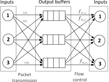
Fig. 2: Routing process in a mini-router of the OQ-UDN central module.
C. Routing in the OQ-UDN modules
We use a dimension order routing in the OQ-UDN mod-ules. The ′M odulo XY′ routing algorithm is simple and
inherently deadlock free. It routes packets along one dimen-sion, then along the second dimension of the mesh and takes advantage of the path diversity by introducing an extra turn before the last column in the topology. The routing algorithm
is incremental. Path computation is processed at every node in the OQ-UDN which removes the packet overhead that all-at-once routing algorithms create. A feedback-control signal is generated at each time a packet tries to access a saturated buffer. The whole routing process in the NoC central modules of the switch is made of two phases: packets transmission and feedback control as illustrated in Fig. 23. The OQ-UDN switch
with small output queues and internal back-pressure control offers lower cost than fabrics with large internal buffers. Although in a MR of degree n, all output ports must run n times faster than an input port to handle the worst case scenario, the required internal speedup is bounded to 3 and the hardware implementation of the module is feasible [13]. Given the technology advance, on-chip logic and memory VLSI implementation costs much less than off-chip communication. Hence, we argue that the OQ-UDN architecture is a proper choice for next-generation switching fabrics.
IV. IMPLEMENTATION COMPLEXITY
In this section, we briefly discuss the implementation complexity of the OQ Clos-UDN switch.
A. Dispatching time
Dispatching packets in the OQ Clos-UDN is non-iterative. At each cell time,mRR input arbiters at the input stage select CMs to dispatch packets requiring a time complexity in the or-der ofO(log m). The dispatching process and packets routing through the OQ-UDN modules work in parallel. Thanks to a pipelined nature of central modules, the dispatching time at time slot t (Dispt) and the packets forwarding through the
NoC (T xt) overlap as Fig. 3 shows. We call F0, the flow of
packets dispatched to a particular OQ-UDN module at time slot t= 0.F0 arrives to the NoC routers of the first column
M0. Forwarding decisions are taken and packets are transferred
3In the figure we useλ
Ix,Oy to refer to the rate of traffic flowing from
inputIato outputObof a mini-router.fOy,Ixdenotes the probability of the
[image:4.612.86.261.475.607.2]Tx1
M0 M1 M2 M3
..
.
..
.
..
.
..
.
Disp0
M4
t=0
Fr
o
m
LI
(
i
,
r
)
T
o
LC
(
r,
j
)
Disp1
Disp2
Disp3
Tx2 Tx1
Tx3 Tx2 Tx1
t=1
t=2
t=3 OQ-R
OQ-R
OQ-R OQ-R
OQ-R
OQ-R OQ-R
OQ-R
OQ-R OQ-R
OQ-R
OQ-R
M0 M1 M2 M4
Tx0
Tx0
Tx0
Tx0
Dispt +Txt Txt-1 Txt-2 Txt-3
Dispatc hed
pac ket f
[image:5.612.153.453.71.215.2]rom IM(i)
Fig. 3: Pipelined working of OQ Clos-UDN dispatching and packets forwarding through central modules.
10 20 30 40 50 60 70 80 90 100
101 102
Offered Load (%)
Average Cell Delay (cell time)
[image:5.612.326.560.249.414.2]OQ−UDN, M=k/16 OQ−UDN, M=k/8 OQ−UDN, M=k/4 OQ−UDN, M=k/2 OQ Clos−UDN, M=k’/2 OQ Clos−UDN, M=k’
Fig. 4: Delay performance of single-stage and multistage(64×64)
switch, underBernoulli i.i.dtraffic,BD= 3.
10 20 30 40 50 60 70 80 90 100
101 102 103
Offered Load (%)
A
ve
ra
g
e
C
e
ll
D
e
la
y
(c
e
ll
tim
e
)
OQ−UDN, M=k/16 OQ−UDN, M=k/8 OQ−UDN, M=k/4 OQ Clos−UDN, M=k’/4 OQ Clos−UDN, M=k’/2 OQ Clos−UDN, M=k’
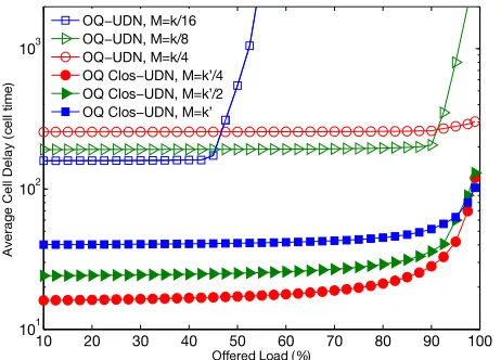
Fig. 5: Delay performance of single-stage and multistage(256×256)
switch, underBernoulli i.i.dtraffic,BD= 3.
to inputs of the next hop. At time slot t= 1, a new flow of packetsF1arrives toM0whileF0gets routed to the next stage
of the UDN.
60 65 70 75 80 85 90 95 100
10−1 100 101 102 103 104
Offered Load (%)
Average Cell Delay (cell time)
MSM/CRRD, iter=2 MSM/CRRD, iter=4 MMM, xbuff=16 MMM, xbuff=1 IQ Clos−UDN, M=k’, SP=1 IQ Clos−UDN, M=k’, SP=4 OQ Clos−UDN, M=k’/4 OQ Clos−UDN, M=k’/2 OQ Clos−UDN, M=k’
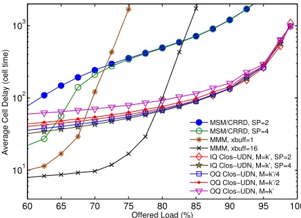
Fig. 6: Average switch latency for MSM, MMM, IQ Clos-UDN and
OQ Clos-UDN, for(256×256)switch size, underBernoulli i.i.d
traffic,BD= 3.
10 20 30 40 50 60 70 80 90 100
102 103
A
ve
ra
g
e
C
e
ll
D
e
la
y
(ce
ll
ti
me
)
M=k/8, BD=3, Burst=5 M=k/8, BD=3, Burst=10 M=k/8, BD=10, Burst=10 M=k/4, BD=3, Burst=5 M=k/4, BD=3, Burst=10 M=k/4, BD=10, Burst=10 M=k/2, BD=3, Burst=5 M=k/2, BD=3, Burst=10 M=k/2, BD=10, Burst=10
[image:5.612.63.285.254.418.2]Offered Load /Ms
Fig. 7: Delay performance of single-stage OQ-UDN (64×64) switch
underBurstyuniform traffic.
B. Hardware requirements
In the OQ Clos-UDN switch, m arbiters per IM are associated to m FIFOs. A queue arbiter selects one among
[image:5.612.331.573.461.630.2] [image:5.612.57.288.473.639.2]CM block at the central stage is made of (k × M) mini-routers. Unlike with IQ-UDN modules [7] where every on-chip router selects packets in a RR manner to forward them to the next hop making the complexity equals toO(log kM), OQ-UDN is fitted with output queues that absorb traffic with respect to their capacity. In [13], authors discuss a possible HW implementation of a single-stage WUDN packet switch that is quite similar to the OQ-UDN. The implementation of a module is perfectly feasible considering the current technology whereby cost/performance trade-off is made by varying the switch parameters and/or the synthesis technology.
V. EXPERIMENTALRESULTS
In this section, we analyse the performance of the proposed switching architecture using an event-driven simulator varying settings of the switch and the traffic type.
A. Uniform packets arrivals
We investigate the average end-to-end packets delay in the switch for different switch sizes, mesh depths (M) and traffic patterns. We set the output buffers’ capacity (BD) to a minimum of 3.
1) Uniform Bernoulli traffic: We test the delay perfor-mance of the OQ UDN switch working as a single stage switch and when being part of the three-stage Clos switch under smooth traffic arrivals. In all figures, we use the notation OQ-UDN to refer to single-stage and OQ Clos-UDN for the multistage architecture. Fig. 4 depicts the variation of the delay metric for a single and three-stage OQ-UDN switch under Bernoulli i.i.d arrivals. Parameters k and k′ respectively
denote the number of I/O ports for a stand alone OQ-UDN and a Clos switch central module. Whether used in a single or multistage architecture, OQ-UDN design offers smooth delay variability for all proportions of input load. However, reducing the NoC’s width (M) deteriorates the single-stage switch’s performance. Conversely, OQ Clos-UDN seems less affected as it keeps on delivering 100% throughput even for smallM values. This mainly reports to what a multistage architecture brings over single-stage switching fabrics. Actually, breaking the whole large NoC into smaller units mounted in a Clos fashion reduces the size of the central modules. It becomes possible to distribute packet flows to various CMs where they are routed through smaller UDNs with much reduced congestion. We note that reducing M leads to saturation of the output-queued NoC structure and that the multistage architecture offers better control on the absolute delay in large-scale switches as Fig. 5 shows. In addition to the relatively high latency that a (256×256) single-stage experiences, altering the number of pipeline stages becomes less efficient for high traffic loads that are relevant for a DCN environment. Setting M =k/4 = 64 ameliorates the delivery ratio. However it is still impractical and non-effective. In Fig. 6, we compare the delay performance of the proposed OQ Clos-UDN switch to an MSM, MMM and the IQ Clos-UDN switching architectures. Our proposal outperforms MSM under heavy workloads. It always provides 100% throughput unlike the IQ Clos-UDN switch that saturates at around 90% if a speedup SP = 1 is used. An MMM architecture affords lower delays. However,
we still need large crosspoint buffers to achieve full through-put. On the contrary, our Clos switch running with small on-chip buffers (BD = 3) and M =k′/4 (that is only equal to
4 for (256×256) switch ports) ensures almost constant delay variations and high delivery ratios.
60 65 70 75 80 85 90 95 100
101 102 103
Offered Load (%)
Average Cell Delay (cell time)
[image:6.612.332.550.133.291.2]MSM/CRRD, SP=2 MSM/CRRD, SP=4 MMM, xbuff=1 MMM, xbuff=16 IQ Clos−UDN, M=k’, SP=2 IQ Clos−UDN, M=k’, SP=4 OQ Clos−UDN, M=k’/4 OQ Clos−UDN, M=k’/2 OQ Clos−UDN, M=k’
Fig. 8: Average switch latency for MSM, MMM,IQ Clos-UDN and
OQ Clos-UDN, for(256×256)switch size, underBurstyuniform
traffic,BD= 3.
10 20 30 40 50 60 70 80 90 100
100 101 102 103
Offered Load (%)
Average Cell Delay (cell time)
[image:6.612.331.552.349.518.2]OQ Clos−UDN, M=k’/4 OQ Clos−UDN, M=k’/2 OQ Clos−UDN, M=k’ MSM/CRRD, iter=2 MSM/CRRD, iter=4 IQ Clos−UDN, M=k’, SP=2 IQ Clos−UDN, M=k’, SP=4
Fig. 9: Delay performance of (64×64) MSM, MMM, IQ Clos-UDN
and OQ Clos-UDN, underU nbalancedtraffic,BD= 3,ω= 0.5.
0 0.2 0.4 0.6 0.8 1 40
50 60 70 80 90 100
Omega
T
h
ro
u
g
h
p
u
t
o
f
S
w
it
ch
MSM/CRRD, iter=2 MSM/CRRD, iter=4 MMM, xbuff=1 MMM, xbuff=16
IQ Clos−UDN, M=k’, SP=1
IQ Clos−UDN, M=k’, SP=2
OQ Clos−UDN, M=k’/4
OQ Clos−UDN, M=k’/2
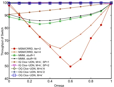
[image:7.612.67.284.65.231.2]OQ Clos−UDN, M=k’
Fig. 10: Throughput stability of different switching architectures for (64×64) switch and variableω.
expansion is limited to 14%. Providing larger queues for the mini-routers, proves to solve the saturation problem at the expense of additional cost. On the whole, the stand alone OQ-UDN as it is, do not scale with the switch size under bursty traffic unlike the Clos switch that shows robustness and flexibility. Fig. 8 illustrates the average end-to-end latency in MSM, MMM, IQ and OQ Clos-UDN switches. We note that under heavy bursty arrivals, both semi-buffered and fully-buffered Clos switching architecture have delay performance that are worse than the NoC-based switches. MMM cannot achieve 100%throughput even if the middle stage buffers are worth of16packets, each. The flexibility of networks-on-chip and a Clos structure with dynamic packets dispatching allow better distribution of the load and conserve high throughput.
B. Unbalanced traffic
We evaluate a (64×64) Clos with OQ-UDN modules under non-uniform traffic for which one fraction of the total input load is uniformly distributed among the switch outputs and the other fraction goes to the output with the same index as the issuing input port. If ω = 0, then the traffic is perfectly uniform. In the other extreme of the margin, if ω = 1, then the switch deals with a totally unbalanced traffic. In Fig. 9 is presented the delay performance of different switching architectures with variable settings, a variable input load and ω= 0.5. As for uniform traffic pattern, OQ Clos-UDN switch responds better than MSM switch with CRRD scheduling. IQ and OQ Clos-UDN switches can have comparable end-to-end latencies through changing the UDN design parameters (mainly speedup and M for the input-queued type and M and BD for an OQ-UDN module). Although both designs are highly customizable, an input-queued structure with no speedup andM =k′= 8 do not achieve full throughput.
Stability of switch throughput: With the help of small on-chip queues in CMs of the Clos switch, incoming traffic is absorbed and transferred from one stage of the NoC to the subsequent stage. Fig. 10 shows that IQ Clos-UDN with full depth (M =k′ = 8) andSP = 1achieves90%throughput. A
buffered MMM architecture provides better delivery ratio than MSM with CRRD scheduling (60% throughput if iter = 4
andω= 0,5). OQ Clos-UDN offers full throughput under the whole range of ω even for minimum settings BD = 3 and M =k′/4 = 2 when the switch size is64×64.
VI. CONCLUSION
The multistage arrangement is relevant to use for large sized packet switches. By means of smaller switching units, it is possible to build large systems with reduced cost and that scale better than common crossbars. In this paper, we propose a highly-performant switch for DCN environment. The central stage modules of the Clos, are Unidirectional NoC fabrics where on-chip mini-routers are fitted with small output queues to absorb traffic. We conjuncture that given the current technology it is possible to build the OQ Clos-UDN switch and embed buffers running at reasonable rates. Simulations show that the architecture outperforms MSM with CRRD scheduling, MMM packet switch and the IQ Clos-UDN under wide range of uniform as well as non-uniform traffics.
ACKNOWLEDGMENT
This work was supported by the EU Marie Curie Grant (SCALE: PCIG-GA-2012-322250).
REFERENCES
[1] N. I. Chrysos, “Request-Grant scheduling for Congestion Elimination in Multi-Stage Networks,” Crete University, 2006, Tech. Rep. [2] C. Clos, “A Study of Non-Blocking Switching Networks,”Bell System
Technical Journal, vol. 32, no. 2, pp. 406–424, 1953.
[3] F. M. Chiussi, J. G. Kneuer, and V. P. Kumar, “Low-cost scalable Switching Solutions for Broadband Networking: the ATLANTA archi-tecture and chipset,”IEEE, vol. 35, no. 12, pp. 44–53, 1997.
[4] Z. Dong and R. Rojas-Cessa, “Non-blocking
Memory-Memory-Memory Clos-network packet switch,” inSarnoff Symposium, 2011 34th IEEE. IEEE, 2011, pp. 1–5.
[5] K. Goossens, L. Mhamdi, and I. V. Senin, “Internet-router buffered crossbars based on Networks-on-Chip,” in Digital System Design, Architectures, Methods and Tools, 2009. 12th Euromicro Conference on. IEEE, 2009, pp. 365–374.
[6] X. Li, Z. Zhou, and M. Hamdi, “Space-Memory-Memory architecture for Clos-Network Packet Switches,” inICC 2005. IEEE, 2005, pp. 1031–1035.
[7] F. Hassen and L. Mhamdi, “A Multi-Stage Packet-Switch Based on NoC Fabrics for data center networks,” inGlobecom Workshops (GC Wkshps), 2015. IEEE, 2015, p. in press.
[8] E. Bastos, E. Carara, D. Pigatto, N. Calazans, and F. Moraes, “MOTIM-A Scalable Architecture for Ethernet Switches,” in VLSI, 2007. ISVLSI’07. IEEE, 2007, pp. 451–452.
[9] F. Moraes, N. Calazans, A. Mello, L. M¨oller, and L. Ost, “HERMES: An infrastructure for low area overhead Packet-Switching Networks on Chip,” INTEGRATION, the VLSI journal, vol. 38, no. 1, pp. 69–93, 2004.
[10] T. Karadeniz, L. Mhamdi, K. Goossens, and J. Garcia-Luna-Aceves, “Hardware design and implementation of a Network-on-Chip based load balancing switch fabric.” inReConFig, 2012, pp. 1–7.
[11] L. Mhamdi, K. Goossens, and I. V. Senin, “Buffered Crossbar Fabrics Based on Networks on Chip.” inCNSR, 2010, pp. 74–79.
[12] A. Bitar, J. Cassidy, N. Enright Jerger, and V. Betz, “Efficient and programmable Ethernet switching with a NoC-enhanced FPGA,” in Proceedings of the tenth ACM/IEEE symposium on Architectures for Networking and Communications Systems. ACM, 2014, pp. 89–100. [13] T. Karadeniz, A. Dabirmoghaddam, Y. Goren, and J.