Grid-tied Inverters: Design, Stability Analysis and Operation Under Grid Faults
.
White Rose Research Online URL for this paper:
http://eprints.whiterose.ac.uk/98576/
Version: Accepted Version
Article:
Konstantopoulos, G.C. orcid.org/0000-0003-3339-6921, Zhong, Q-C. and Ming, W-L.
(2016) PLL-less Nonlinear Current-limiting Controller for Single-phase Grid-tied Inverters:
Design, Stability Analysis and Operation Under Grid Faults. IEEE Transactions on
Industrial Electronics, 63 (9). 7465781. pp. 5582-5591. ISSN 0278-0046
https://doi.org/10.1109/TIE.2016.2564340
© 2016 IEEE. Personal use of this material is permitted. Permission from IEEE must be
obtained for all other users, including reprinting/ republishing this material for advertising or
promotional purposes, creating new collective works for resale or redistribution to servers
or lists, or reuse of any copyrighted components of this work in other works
eprints@whiterose.ac.uk https://eprints.whiterose.ac.uk/
Reuse
Unless indicated otherwise, fulltext items are protected by copyright with all rights reserved. The copyright exception in section 29 of the Copyright, Designs and Patents Act 1988 allows the making of a single copy solely for the purpose of non-commercial research or private study within the limits of fair dealing. The publisher or other rights-holder may allow further reproduction and re-use of this version - refer to the White Rose Research Online record for this item. Where records identify the publisher as the copyright holder, users can verify any specific terms of use on the publisher’s website.
Takedown
If you consider content in White Rose Research Online to be in breach of UK law, please notify us by
PLL-less Nonlinear Current-limiting Controller for
Single-phase Grid-tied Inverters: Design, Stability
Analysis and Operation Under Grid Faults
George C. Konstantopoulos,
Member, IEEE,
Qing-Chang Zhong,
Senior Member, IEEE
and Wen-Long Ming
Abstract—A nonlinear controller for single-phase grid-tied
inverters, that can operate under both a normal and a faulty grid with guaranteed closed-loop stability, is proposed. The proposed controller acts independently from the system parameters, does not require a phase-locked loop (PLL) and can achieve the desired real power regulation and unity power factor operation. Based on nonlinear input-to-state stability theory, it is analytically proven that the inverter current always remains below a given value, even during transients, independently from grid variations or faults (short circuit or voltage sag). The desired performance and stability of the closed-loop system are rigorously proven since the controller has a structure that does not require any switches, additional limiters or monitoring devices for its implementation. Therefore, nonlinear stability of a grid-tied inverter with a given current-limiting property is proven for both normal and faulty grid conditions. The effectiveness of the proposed approach is experimentally verified under different operating conditions of the grid.
Index Terms—single-phase inverter, nonlinear control, current-limiting property, grid fault, stability
I. INTRODUCTION
T
HE number of distributed generation (DG) unitscon-nected to the power network has been continuously increasing during the last decades [1]. Although this fact has provided substantial economical benefits for both utility companies and customers, it has also led to more stringent demands regarding the interconnection of DGs with the grid because they directly affect the stability of the power network [2]. Therefore, the operation and control of grid-tied inverters, that link the DG units with the utility grid, are crucial and should be maintained inside some given limits under both normal and abnormal conditions of the grid.
Various control methods have been proposed in the literature for grid-tied inverters to control the output current or the power injected to the grid, while maintaining a desired output voltage [3], [4], [5], [6]. Although in most of the cases, a PLL is applied to synchronize the inverter with the grid, this can result in oscillations or a dc offset at the measured frequency that degrades the inverter performance [7]. Hence, recently,
G. C. Konstantopoulos and W.-L. Ming are with the Department of Automatic Control and Systems Engineering, The University of Sheffield, Sheffield, S1 3JD, UK (e-mail: g.konstantopoulos@sheffield.ac.uk, w.ming@sheffield.ac.uk).
Q.-C. Zhong is with the Department of Electrical and Computer Engi-neering, Illinois Institute of Technology, Chicago, IL 60616, USA, and the Department of Automatic Control and Systems Engineering, The University of Sheffield, Sheffield, S1 3JD, UK (e-mail: zhongqc@ieee.org).
The financial support from the EPSRC, UK under Grant No. EP/J01558X/1 is greatly appreciated.
several control strategies that possess a self-synchronization mechanism have been developed to result in a PLL-less control operation which increases system reliability and assist in maintaining a stable performance [8], [9], [10], [11], [12]. Since stability of grid-tied inverters is of major importance, usually small-signal model analysis is applied to achieve a stable closed-loop system around a desired operating point [13], [14], [15]. In order to obtain global stability results, several Lyapunov-based controllers have been developed for both the grid-connected and islanded operation of inverters [16], [17], [18], [3]. These methods represent a powerful tool for controlling the inverter and stabilizing the closed-loop system during normal operating conditions, but may require a redesign in the cases of grid faults, in order to maintain the inverter current below a given value, especially when the control task is the output power regulation and when the system parameters vary.
The operation of grid-tied inverters under grid-fault con-ditions (short circuit or voltage sag) has been extensively studied in the literature [19], [20], [21], [22]. During the fault, the grid voltage drops and the inverter often tries to regulate the power injected to the grid, which leads to high inverter currents. Hence, fault current-limiting controllers are essential for protection purposes. This can be achieved by either triggering suitably designed protection circuits [21], [23], [24] or by using several low-voltage ride-through con-trollers [25], [26], which will keep injecting power to the grid with a limited current. From a control systems point of view, most of the current protection methods are based on a switching control action between the power regulation during normal grid operation and the current-limiting scheme after the fault has occurred [27], [19], [28], [29], [30], [31]. Virtual impedance methods have been also proposed in order to guarantee a given limit of the inverter current [32], [33], and can be also found in several microgrid systems [34], [35]. However, most of the existing methods for improving the fault-ride-through capability of inverters are based on algorithmic control schemes and lack from a stability proof in order to mathematically prove that the current will always remain below a given maximum value, even during transients.
of a grid fault. Introducing a current saturation unit in the control structure can be devastating for the inverter and lead to undesired oscillations, mainly caused by integration wind-up [32]. Additionally, the inverter should be able to return to its initial condition after the fault is cleared and avoid latch-up issues [36]. The unpredicted grid variations and the nonlinear dynamics of the closed-loop system, caused by the nonlinear expressions of the real and reactive power, make the proof of stability a difficult task. By adding to this issue the dynamic performance of the phase-locked loop (PLL) required for the synchronisation, which plays an important role especially under grid faults [37], the complexity of the closed-loop system is significantly increased. This is the main reason for implementing control structures that can operate under grid fault conditions without a PLL, as it has been recently reported in [12], [38].
In this paper, a nonlinear controller for single-phase grid-tied inverters is proposed in order to guarantee a current-limiting property under both normal grid operation and grid faults. The proposed controller is independent from the system parameters, does not require a PLL and has the same structure under both normal and faulty grid conditions. Therefore, it is proven that real power regulation and unity power factor operation can be achieved without additional saturation units, switches or monitoring devices. The proposed control structure allows a rigorous stability proof of the closed-loop system based on nonlinear input-to-state-stability (ISS) theory with a given limit of the inverter current at all times independently from grid variations. The proof of stability is also established independently from the frequency of the grid, while the current-limiting property of the proposed controller guarantees a given limit at the injected power, which is crucial in cases of large transients or grid faults. An analytic framework of selecting the controller parameters and overcoming practical implementation issues (e.g. implementation using a DSP or under distorted grid) is also provided together with the effect of the output filter to the closed-loop system. Extensive experi-mental results are presented to demonstrate the effectiveness of the proposed controller using a grid simulator for performing the grid-fault scenarios and using the public grid, including the start-up case or when the system parameters change.
[image:3.612.319.554.57.142.2]II. PROBLEM FORMULATION
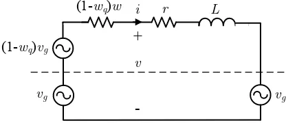
Fig. 1 describes the system under consideration. It consists of a single-phase inverter connected to the grid through a filter with inductanceLand parasitic resistancer. The filter can be other types as well but in order to simplify the exposition in the sequel it is assumed that it is anLfilter. The grid voltage is denoted asvg, while the inverter output voltage and current are
v andi, respectively. The inverter is assumed to be controlled using a pulse-width-modulated (PWM) generator with high frequency and therefore the voltage v can be assumed the same as the average voltage over a switching period [1].
As a result, the dynamic model of the system is given as
Ldi
dt = −ri+v−vg, (1)
dc
V +
-DC
AC
L
r i
+
-v vg
Single-phase inverter
[image:3.612.319.562.628.671.2]PWM signals
Figure 1. A single-phase grid-tied inverter with anLfilter
which is linear and the control input is described by the inverter voltagev.
However, in most grid-tied inverter applications, the main tasks are to achieve real and reactive power regulation. Par-ticularly, the real powerP should be regulated to a reference value Pset and the reactive powerQ should remain equal to zero to achieve unity power factor operation. The reference value Pset can be defined by a supervisory control scheme or other control functions that can be found in renewable energy systems, such as maximum power point tracking, dc bus voltage regulation, etc.
In this paper, the real power P and reactive power Q are considered at the grid side, i.e., after the filter. However, in many applications, they are calculated at the output of the inverter using the inverter voltagevinstead of the grid voltage
vg. Since in most of the cases the inductor does not cause a significant phase shifting or voltage drop between the voltages
v and vg [1], [4], the difference is insignificant. Due to the multiplication of the signals v or vg with the state i of the system in the power expressions, the closed-loop system with any control scheme will be nonlinear, and therefore the proof of closed-loop system stability represents a difficult task. The objective of this paper is to design a controller that is able to limit the inverter current under both normal and faulty conditions and prove the closed-loop stability.
III. THE PROPOSED CONTROLLER
A. Control structure
In order to achieve the desired real power regulation at the reference valuePsetand at the same time unity power factor operation, the following nonlinear controller is proposed:
v = vg+ (1−wq)(vg−wi), (2)
where the variables w andwq are the controller states given from the nonlinear dynamics
˙
w=−c(Pset−P)wq2 (3)
˙
wq=
w−wm ∆w2
m
c(Pset−P)wq−k (
(w−wm) 2
∆w2 m
+w2q−1 )
wq (4)
with wm,∆wm, k and c being positive constants. It can be easily seen that the proposed controller is independent from the inverter and filter parameters and does not require a PLL for its implementation, which improves system robustness and reliability.
controller Lyapunov function
W = (w−wm) 2
∆w2 m
+wq2. (5)
Taking the time derivative ofW and substituting the controller dynamics (3)-(4), it yields
˙
W =−2k
(
(w−wm)2 ∆w2
m
+wq2−1 )
w2q. (6)
The value of W˙ is zero on the ellipse
W0= {
w, wq ∈R:
(w−wm)2 ∆w2
m
+w2q = 1 }
,
negative outside the ellipse and positive inside the ellipse except from the horizontal axis (wq = 0) where it is zero. For any initial control states (w0, wq0)on the ellipseW0, the trajectory of the controller states will start and stay on the ellipse for all future time; see Fig. 2. In this paper, the initial conditions of the controller are chosen as
w0=wm, wq0= 1. (7)
In other words, the controller states are restricted onW0 and
w ∈ [wmin, wmax] = [wm−∆wm, wm+ ∆wm],∀t ≥ 0. Therefore, the control states can be represented by the trans-formation
w = wm+ ∆wmsinφ
wq = cosφ,
whereφis the angle of the control state vector with respect to the initial value, as shown in Fig. 2. According to the controller dynamics (3)-(4), there is
˙
φ= c(P−Pset)wq
∆wm
, (8)
which is the angular velocity that the controller states wand
wq move on the ellipse W0. Hence, when the real power
P approaches the reference value Pset, the angular velocity tends to zero and the controller states stop and converge to two constant values we andwqe. Then, from (2), the inverter voltage becomes
v = vg+ (1−wqe)(vg−wei). (9)
For a typical L filter that does not impose significant phase difference betweenvandvg, it is obvious from (9) that bothv andvg are practically in phase with the currentiand therefore both control tasks (real power regulation and unity power factor) can be achieved. A more detailed analysis regarding the effect of the filter is provided in Section V.
From the controller structure (2), one can easily see that since the controller state w is multiplied by the current i to obtain a voltage,wrepresents a time-varying virtual resistance. This is significantly different from existing virtual impedance methods, e.g. [32], [35], since the controller dynamics are embedded into the virtual resistance w. For stability reasons, it is required that w >0,∀t≥0. In order to achieve this, the
1
W0 wq
w wmax we
wqe
φ
ɺwm wmin
[image:4.612.362.512.54.137.2]φ
Figure 2. Phase portrait of the controller dynamics
controller parameters should be chosen to satisfy:
wm>∆wm>0
so that the ellipseW0 stays on the right-half plane.
It should be also noted that the angular velocity φ˙, given from (8), can be zero on the horizontal axis as well, i.e. when wq = 0. This is desirable in order to avoid a possible oscillating behavior of the controller dynamics around W0 on the w −wq plane. Particularly, if the controller states pass the desired equilibrium point during transients and tend to reach the horizontal axis, then wq → 0 and as a result
˙
φ→0independently from the differenceP−Pset. Thus, the controller states slow down until the angular velocity changes sign and forces them to return to the desired equilibrium. Consequently,wandwq cannot travel around the whole ellipse
W0 and, based on the given initial conditions (7), they are restricted on the upper semi-ellipse ofW0 as shown in Fig. 2. Hence,wq ∈[0,1].
By defining the initial conditions of the controller states from (7), a smooth connection to the grid can be achieved. Since initially wq0 = 1 holds true, then according to (2), the initial inverter voltage is v = vg until the real-power reference Pset is changed to a non-zero value. Therefore, a smooth connection of the inverter can be achieved without the need of a PLL. There is no need to have a pre-synchronisation period and one can simply directly connect the inverter to the grid and enable the controller.
B. Stability analysis and current-limiting property
By substituting the proposed controller (2)-(4) to the system dynamics (1), the closed-loop system becomes
Ldi
dt = −(r+ (1−wq)w)i+ (1−wq)vg. (10)
As it has been shown in the previous subsection, the controller dynamics can be handled independently and result in w ∈
[wmin, wmax] = [wm−∆wm, wm+ ∆wm] and wq ∈ [0,1] for allt≥0. The equivalent circuit of the closed-loop system can then be simplified as shown in Fig. 3, where the dashed line is used to indicate that the grid voltagevgcan be canceled by the same term in the controller and result in the simplified system given by (10).
Therefore, the closed-loop system (10) can be investigated as a non-autonomous system with time-varying signals w(t) andwq(t)bounded inside their given sets. Consider now the Lyapunov function
V =1 2Li
L r
i
vg
+
-vvg
(1-wq)w
[image:5.612.73.281.62.152.2](1-wq)vg
Figure 3. Closed-loop system equivalent circuit
The time derivative of V results in ˙
V = −(r+ (1−wq)w)i2+ (1−wq)vgi ≤ −(r+ (1−wq)wmin)i2+|(1−wq)vg| |i|
< 0, ∀ |i|> |(1−wq)vg| r+ (1−wq)wmin
(11)
because w > wmin > 0 and wq ∈ [0,1]. As a result, the system (10) is input-to-state stable (ISS) [39] and the inverter current i is bounded for any bounded grid voltage
vg. Considering as vg = √
2Vgsin(ωt), where Vg and ω are the RMS grid voltage and angular frequency, respectively, then
|i| ≤ (1−wq) √
2Vg
r+ (1−wq)wmin
, ∀t≥0, (12)
as long as the current is initially (t= 0) inside the previous range. This inequality holds since according to (11) the derivative of the Lyapunov function is negative outside the range imposed by (12) for the inverter current. Based on the fact that (12) is satisfied for all t≥0, then
I≤ (1−wq)Vg r+ (1−wq)wmin
, ∀t≥0,
whereIis the RMS value of the inverter current. For the given maximum allowed RMS current Imax, ifwmin is chosen as
wmin=
Vg
Imax
, (13)
then there is
I≤ (1−wq)Vg r+ (1−wq)wmin
< Vg wmin
=Imax,∀t≥0,
for an initial currentI(0)< Imax. In other words, the current will never exceedImax, which guarantees the current-limiting property of the proposed controller and the nonlinear stability of the closed-loop system. Since unity power factor is achieved at the steady state, for a given grid voltage Vg, the proposed controller can regulate the inverter at any real power reference
Pe =Pset with 0 < Pset ≤Pmax, where Pmax =VgImax. This corresponds to some constant valueswe∈[wmin, wmax] and wqe ∈ [0,1]. However, if Pset > Pmax is chosen, then no virtual resistance we exists in the given bounded range [wmin, wmax]to lead the real power toPsetand therefore the controller states w andwq will move anti-clockwise on W0 since φ <˙ 0 (from P−Pset<0) and converge to the point (we, wqe) = (wmin,0), which is also an equilibrium point of the closed-loop system from the controller dynamics (3)-(4). In this case, the inverter will be regulated to Pe=Pmax< Pset
in order to maintain the current-limiting property.
It should be noted that in the case where the grid voltage slightly varies (e.g. weak grid, grid impedance variations) and hence Vg ∈[0, Vmax], then wmin can be chosen as wmin =
Vmax
Imax to guarantee the current-limiting property at all times
according to the ISS property (11).
C. Selection of controller parameters
Sincewis bounded in a given set[wmin, wmax] represent-ing a virtual resistance and the minimum wmin corresponds to a maximum current Imax, similarly, the maximum wmax can be chosen to be related to a minimum currentImin as
wmax=
Vg
Imin
. (14)
Since the minimum current should be also very close to zero, when Pset is set zero, then Imin can be selected arbitrarily small (a few mA or µA). This is reasonable since even if the inverter is not connected to the grid or Pset= 0, a small current keeps flowing through the parasitic elements of the converter and the filter.
After having defined wmin andwmax from (13) and (14), respectively, the controller parameterswmand∆wmrequired for the implementation are obviously given as
wm=
wmax+wmin
2 =
Vg 2
( 1
Imin
+ 1
Imax )
, (15)
∆wm=
wmax−wmin
2 =
Vg 2
(
1
Imin − 1
Imax )
, (16)
because they correspond to the coordinate of the center point of ellipseW0 and the horizontal radius, respectively.
The controller gain kshould be chosen as a large positive value since it increases the robustness of thewqdynamics with respect to external disturbances or computational errors, i.e. if the controller states are disturbed from their desired trajectory on the ellipseW0, they will quickly return to it.
Finally, the controller parameter c affects the dynamic performance of the controller since it is found inside the angular velocity φ˙ in (8). In order to define a framework for choosing c, a worst case scenario to obtain its minimum value is considered here. Assume a maximum power difference |Pset−Pinitial|, which is obviously equal to Pmax, and that the controller states start from the upper point of the ellipse (w0, wq0) = (wm,1) and converge to the final point (we, wqe) = (wmin,0)at the steady state. Lettsbe the settling time required for the system to reach its steady-state values, thenwandwq will travel on an arc with central angle π2 rad and angular velocity φ˙; see Fig. 2. The angular velocity and the controller statewq will decrease as the system approaches its steady-state values and therefore considering a worst-case scenario where φ˙ = ˙φmax = 2tπs rad/s and wq = 1 are constant, then
˙
φmax=
cPmax
∆wm
= π
2ts and as a result
c= π∆wm 2tsVgImax
i vg
PWM Generator
--c
× w
× v
Equation (4) wq
Pset Power Calculation
1
s
1
-P
F(s)
F(s)
×
-PWM
[image:6.612.74.272.58.185.2]signals
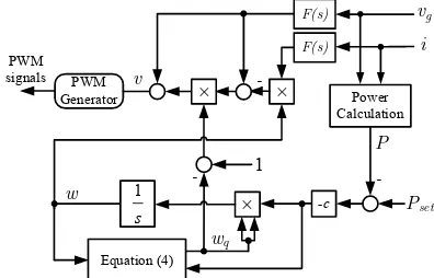
Figure 4. Proposed controller implementation
Note that the parameterc given by (17) is based on a worst-case scenario and therefore represents a way to choose the initial value. In practice,ccan be further increased to improve the dynamic performance and achieve an acceptable time response. Therefore, the settling timetscan be chosen smaller than the original value until a satisfactory response is achieved.
D. Practical implementation
Since the proposed controller is designed on the basis of the mathematical model of the inverter, in reality there are some issues that need to be addressed. Based on the controller structure (2), the measured signals vg andi are directly used in the control input v and therefore they represent feed-forward terms which can introduce a small delay due to the measurement and communication circuits. To overcome this small delay, a phase-lead low-pass filterF(s)can be used for the measurements ofvgandi, which is a common solution in this case [1]. Hence, the proposed controller is implemented as shown in Fig. 4, where it is clear that no PLL is required. Since the proposed controller introduces a continuous-time structure (2)-(4) and in most of the applications the controller is required to be implemented using a DSP, a discretization method is needed (e.g. the Tustin’s approximation). The use of the phase-lead low pass filter is also important to deal with small delays caused by the analog-to-digital (and vice versa) conversion during the implementation of the controller.
IV. OPERATION UNDER GRID FAULTS
Assume that the grid voltage is given asvg= √
2Vgsinωt, whereω is the grid frequency. When the inverter is connected to a stiff grid, there is Vg = Vn and ω = ωn, where Vn andωn represent the rated voltage and frequency, respectively. According to the analysis described in the previous section, closed-loop system stability is guaranteed for any bounded grid voltageVg and for any frequencyω (since the frequency doesn’t affect the analysis). Additionally, since the selection of wmin is given from (13) where Vg = Vn (considering a stiff grid), the current-limiting property is guaranteed for any
Vg ≤Vn and for any ω. This includes the inverter operation under grid faults as it is better explained below:
A. Case 1: Short circuit
Assuming that a short circuit occurs at the grid voltage, then
vg= 0 and the closed-loop system (10) becomes
Ldi
dt = −(r+ (1−wq)w)i, (18)
which means that the currentiwill exponentially converge to zero sincew∈[wmin, wmax]>0 and1−wq ≥0. Assuming that initially the inverter injects some real powerP =Pset>0 to the grid, when the fault occurs it results in P →0 since
vg = 0. Opposed to the traditional control methods that will try to regulate P to Pset by increasing the current to high values that violate the maximum limit, the proposed controller forces the inverter current to exponentially converge to zero, satisfying the current-limiting property and protecting the inverter. Additionally, sinceP−Pset<0, then the angular velocity φ˙ becomes negative and the controller states w and
wq converge to the values wmin and 0, respectively. When the fault is cleared, the closed-loop system becomes again as the one in (10) which forces the current i to increase and converge again to the desired value. Furthermore, during
the fault wq → 0 which results from (3) that w˙ → 0
and the integration automatically slows down. As a result, the proposed controller can overcome wind-up and latch-up problems without additional switches or monitoring devices. These are fundamental issues in grid-tied inverters under grid faults [36], which can be tackled by the proposed controller.
B. Case 2: Voltage sag
Assume now that instead of a short circuit, a voltage sag occurs to the grid with a percentage p×100%, i.e. the grid voltagevg becomes ¯vg = (1−p)vg, where vg represents the original voltage of the grid with rated RMS value. Hence, by substitutingvg withv¯gin the original plant dynamics (1) and in the controller (2) (since the controller uses the measurement of the grid voltage), then the closed-loop system (10) becomes
Ldi
dt =−(r+ (1−wq)w)i+ (1−wq)(1−p)vg, (19)
which according to the same stability analysis as in (11) yields
I≤(1−p) (1−wq)Vg
r+ (1−wq)wmin
<(1−p)Imax. (20)
Therefore the RMS voltage of the inverter current I still remains less thanImax. In fact, ifPset≤(1−p)VgImaxthen the real powerP will converge toPsetafter a small transient, while ifPset>(1−p)VgImax, then P will converge to the value Pe = (1−p)VgImax < Pset, since in this case the current I will reach its upper limit, which is (1 −p)Imax according to (20). Once again, when the fault is cleared, the system will return to its original values after a small transient.
V. EFFECT OF THE OUTPUT FILTER TO THE CLOSED-LOOP SYSTEM
A. L filter
phase shifting in order for v, vg andito be almost in phase at the steady state in (9) and result in the desired unity power factor. Hence, a framework for designing the output filter of the inverter is required. Since it is proven in Section III that
w∈[wmin, wmax]andwq ∈[0,1], then from the closed-loop system equation (10), a set of transfer functionsG(s) = vi(s)g(s) can be obtained with respect to w and wq, which operate exclusively on W0, in the following form
G(s) = i(s)
vg(s)
= 1−wq
Ls+r+ (1−wq)w
. (21)
After some calculations, it yields that
|G(jω)| = √ 1−wq
(r+ (1−wq)w)2+ (ωL)2
, (22)
∠G(jω) = arctan
(
− ωL
r+ (1−wq)w )
. (23)
If the grid voltagevgand the inductor currentiare almost in phase, i.e., they have a very small phase difference, then from (2) it yields that v andi are almost in phase and the power factor is almost equal to 1. In practice, a power factor of 0.99 is acceptable. This corresponds to a phase shift of 8o
at the fundamental frequency (ω= 100π) forG(jω).
As a result from (23) there is
L < 0.0014 (r+ (1−wq)w)
π . (24)
Since this inequality should be guaranteed for every w ∈
[wmin, wmax]andwq ∈[0,1], the lowest value corresponds to the case wherewq = 1which yieldsL <0.00045rand is very restrictive. However, when wq = 1, then from (22) there is |G(jω)|= 0and the phase shifting doesn’t play any role since the magnitude is zero. In fact, for wq = 1, then from (2) it holds thatv=vgand the current that flows is zero. In order to define a framework for choosingL, one can consider a current rangeI∈[I˜min, Imax
]
that is of interest for achieving power
factor very close to 1, where Vg wm <
˜
Imin < Vg
wmin =Imax,
since wm corresponds to zero current andw starts from wm and travels on the ellipse W0 towards wmin. Then the filter inductance can be designed to satisfy
L <0.0014
r+ min{(1−√1−(w−wm)2 ∆w2
m )w
}
π (25)
for allw∈[wmin, Vg ˜ Imin
]
. Taking as an example the parame-ters of Table I and assuming I˜min = 0.25A, then inequality (25) is satisfied. Additionally, for a givenLfilter (with param-eters shown in Table I), the Bode plot of the set of transfer functions (21) can be obtained when w ∈ [wmin,
Vg ˜ Imin
] , as illustrated in Fig. 5 to verify that during the whole operation of the proposed controller, the phase shifting betweenvg and
i at the fundamental frequency will be less than8o.
B. LCLfilter
In many grid-tied inverter applications, the Lfilter is often replaced by an LCL filter to achieve better harmonic attenu-ation. In these cases, the capacitor C is chosen small enough
Magnitude (dB)
-100 -80 -60 -40 -20
101 102 103 104 105
Phase (deg)
-90 -45 0
Bode Diagram of G(s)=i(s)/vg(s)
Frequency (Hz) System: G
[image:7.612.329.533.66.242.2]Frequency (Hz): 50 Phase (deg): -1.71
Figure 5. Bode plot ofG(s) =vi(s)
g(s) forw∈
[
wmin, Vg ˜
Imin
]
to avoid injecting reactive power to the system. Therefore, for a typical LCL filter with small capacitance C and a grid-side inductance Lg, the proposed controller can be applied to achieve the same current-limiting property and stability analysis. This is due to the fact that for low frequencies, the impedance of the shunt capacitor is large and the closed-loop system analysis coincides with the one presented in the previous section for a filter with inductanceL+Lg. Hence, for the filter design, (25) can be used by replacing L andr
withL+Lg andr+rg, respectively. However, for any value of the capacitor C, one can calculate the transfer function
G(s) = vi(s)
g(s) and obtain the Bode plots in the same range
to verify whether the phase difference is small for a given selection of the filter parameters.
VI. EXPERIMENTAL VALIDATION
[image:7.612.61.301.159.253.2]In order to verify the proposed nonlinear PLL-less current-limiting controller, the experimental setup of Fig. 6 was used. The single-phase inverter, fed by the Agilent N8944A power supply, was connected to the Chroma 61860 regenerative grid simulator for performing the grid-fault scenarios or to the public grid. A WT 1600 power analyser from Yokogawa was used to measure the real and reactive power injected to the grid. The proposed controller was implemented using sinusoidal PWM with a switching frequency of15kHz and the TMS320F28335 DSP with a sampling frequency of 4 kHz. The parameters of both the inverter and the controller are shown in Table I, where anLCL filter was used at the inverter output and the dc input voltage from the power supply was 200V. In order to overcome the delay caused by the feed-forward terms, the following phase-lead low-pass filter is applied at the measurements ofvg andi[1]:
F(s) = 33(0.05s+ 1) (s+ 300)(0.002s+ 1).
A. Validation using the grid simulator
1) Operation under normal gridá: Considering a normal
Inverter
Chroma 61860 grid simulator WT 1600
power analyser
[image:8.612.73.276.55.176.2]DC power supply
Figure 6. Experimental setup
Table I
EXPERIMENTAL SETUP AND CONTROLLER PARAMETERS
Parameters Values Parameters Values
L,Lg 2.2mH switching frequency 15kHz
r,rg 0.5 Ω grid frequency 50Hz
C 10µF Imax 2A
Vg 110V Imin 0.1A
Prated 200W k 1000
wm 577.5 Ω ts 0.1s
∆wm 522.5 Ω c 37.3 Ω/V s
Initially the circuit breaker is open and the PWM operation is initiated at the time instantt1. A small amount of negative reactive power is observed due to the capacitor of the LC
filter. At t2, the circuit breaker closes and the real power is set to Pset = 50 W. At the time instant t3, Pset is changed to 100W and finally at the time instant t4, Pset is set to 250W. It is observed that until the time instantt4, the inverter regulates the real power at any reference level. However, when
Pset = 250W, the real power is regulated at around 188W,
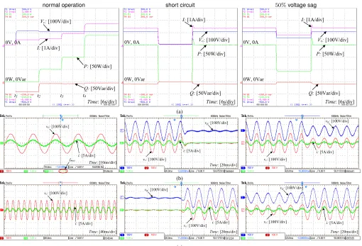
because the inverter current tries to violate the maximum limit of Imax = 2A. This verifies the current-limiting property of the proposed controller, which maintains the inverter operation inside the required range of the current. The left column of Fig. 7(a) shows the response of the capacitor voltageVc, which remains almost constant during the whole operation, and the inverter currentIwhich increases according to the desired real power until the maximum limit is achieved. In order to check this current-limiting property more clearly, the steady-state responses of the capacitor voltagevc and the inverter currenti are given in the left column of Fig. 7(b), where the maximum RMS value of the current is 1.72 A since the controller parameter wmin has been selected according to (13), where the parasitic resistance r has been neglected. In practice, this small resistance will result in limiting the current to a slightly smaller value but even in this case I < Imax holds true as required1. The almost unity power factor operation (over 0.99 measured during the whole grid-connected operation which is acceptable in practice) is observed in the left column of Fig. 7(a), where the reactive power Qis kept to very small values during the whole controller operation and is also depicted in the left column of Fig. 7(b), where the capacitor voltage and the inverter current are almost in phase. In order to verify the current limitation and the unity power factor during transients, the transient performance of vc andiaround the time instant
1In practice, one can setI
maxto a slightly higher value to cover the losses
of the parasitic elements.
t4 is shown in the left column of Fig. 7(c).
2) Operation under grid faults: To further evaluate the
proposed controller, two different grid-fault scenarios are investigated while the system is operating atPset= 150 W.
Case 1: Short circuit
Initially, a short-circuit scenario is investigated where the grid voltage suddenly drops to a very small value (less than 5 V) and is cleared after a small period of time. As shown in the middle column of Fig. 7(a), during the fault, both the real and reactive powers quickly converge to zero and return to their initial values after a small transient, when the fault is cleared. The transient responses when the fault occurs and when the fault is cleared shown in the middle column of Fig. 7(b) and Fig. 7(c), respectively, illustrate that when the short-circuit occurs at the grid voltage, the current quickly converges to zero as it has been theoretically proven in the paper. Particularly, there is a fast reducing oscillation of the current and not a direct exponential convergence due to the small transient of the grid voltage and also due to theLCLfilter used. In the same framework, when the fault is cleared (see the middle column of Fig. 7(c)), the current quickly returns to its original value after a small transient showing that the proposed controller does not suffer from latch-up or wind-up issues.
Case 2: 50% voltage sag
The responses of the real and reactive powers during the 50% voltage sag of the grid voltage are shown in the right column Fig. 7(a). During the fault, the real power is regulated to a lower value corresponding to the limit of the inverter current since according to the analysis of Subsection IV-B, the current
I should be limited below Imax×50% = 1 A. In fact, the proposed controller leads the current to converge to slightly lower than 1 A (0.8 A was measured at the steady state) verifying the theoretical analysis, opposing to the traditional techniques that will increase the current to high values in order to maintain the desired real power. The transient response of the voltage and current waveforms during the grid fault are shown in the right column of Fig. 7(b) and Fig. 7(c).
B. Validation using the public grid
normal operation short circuit 50%voltage sag
t1
Time: [6s/div]
Q: [50Var/div]
Vc: [100V/div]
t2 t3 t4
P: [50W/div]
I: [1A/div]
0W, 0Var 0V, 0A
Time: [6s/div] Q: [50Var/div]
P: [50W/div]
Vc: [100V/div]
I: [1A/div]
0W, 0Var 0V, 0A
Time: [6s/div] Q: [50Var/div]
P: [50W/div]
Vc: [100V/div]
I: [1A/div]
0W, 0Var 0V, 0A
(a)
Time: [10ms/div] i: [5A/div]
vc: [100V/div]
Imax
Time: [20ms/div]
i: [5A/div] vc: [100V/div]
vg: [100V/div]
Time: [20ms/div]
i: [5A/div] vc: [100V/div]
vg: [100V/div]
(b)
Time: [40ms/div]
i: [5A/div] vc: [100V/div]
Time: [20ms/div]
i: [5A/div] vc: [100V/div] vg: [100V/div]
Time: [20ms/div]
i: [5A/div] vc: [100V/div]
vg: [100V/div]
(c)
Figure 7. Operation under normal grid: (a) time response of the real, reactive power, capacitor voltage and inverter current, (b) steady-state response, (c) transient response around time instantt4(left column). Operation under grid faults: (a) time response of the real, reactive power, capacitor voltage and inverter current, (b) transient response when the fault occurs, (c) transient response when the fault is cleared (middle column: short circuit of the grid voltage, right column: 50% grid voltage sag)
At t = 8s, the desired power is changed to Pset = 200W and the system regulates the real power at the reference after a short transient, while at t = 14s, the reference power is set to Pset = 350W and the output power is regulated near to 300W because the inverter current increases and tries to reach the maximum value Imax = 3A. Hence, the current-limiting capability of the controller is verified and is clearly shown in Fig. 8(a), where the RMS value of the inverter current is limited slightly below Imax, as explained in the previous subsection. The responses of the current and voltage of both the inverter and the grid near the time instant t = 14s are shown in Fig. 8(c), which verify the current-limiting capability of the controller during the steady-state and during transients as well as the desired unity power factor. The total harmonic distortion of the grid current has been measured at11%, which is relatively high but can be further improved if a different
LCLfilter is used or a different PWM method is applied [1].
To investigate the effectiveness of the proposed strategy under changes of the system parameters, a sudden change is applied at the dc input voltage from200V to220V while the system operates at Pset = 200W. As shown in Fig. 9, both currents slightly increase and return to their original values after a short transient. Note that in this case, the change of the
dc voltage is not incorporated in the controller to define the duty ratio of the inverter. In practice, the dc input voltage can be measured to define the duty ratio for the PWM generator. To further evaluate the performance of the controller un-der different system parameters, a different inductance L is experimentally tested whereL= 4.4mH. The same scenario as in Fig. 8 is assumed for the reference Pset. The results are shown in Fig. 10 where it is observed that the proposed controller can achieve the desired regulation and unity power factor with a current-limiting capability independently from the filter inductor. In fact, the current is limited to a lower value due to the larger parasitic resistance of the inductor (r= 1 Ω). The transient response at the current-limiting scenario is shown in Fig. 10(b), where the unity power factor is maintained but the quality of the grid current has worsen. This is an indication of the importance of the filter design in the power quality and represents a useful result for further controller improvement.
VII. CONCLUSIONS
[image:9.612.53.563.53.400.2]Time: [2s/div] I: [1A/div]
Vc: [5V/div] P: [100W/div]
Q: [100Var/div] 0W,0Var
0A,105V
(a)
Time: [20ms/div]
ig: [5A/div]
vc: [100V/div] i: [5A/div]
vg: [100V/div]
(b)
Time: [20ms/div]
ig: [5A/div]
vc: [100V/div]
i: [5A/div]
vg: [100V/div]
[image:10.612.80.271.52.349.2](c)
Figure 8. Operation under public grid (Table I parameters): (a) time response of the real, reactive power, capacitor voltage and inverter current, (b) transient response during start up (t=2s) and (b) transient response around14s
Time: [20ms/div]
ig: [5A/div]
vc: [100V/div] i: [5A/div]
vg: [100V/div]
Figure 9. Operation under dc input voltage change from200V to220V
a PLL, thus leading to a simple and reliable implementation. Without the need of any external protection circuit (switches, saturation units, monitoring, etc.), the controller limits the inverter current below a given maximum value at all times. The proposed controller performance was analytically tested using a suitable experimental setup under both normal and faulty grid conditions.
ACKNOWLEDGMENT
The authors would like to thank Chroma Systems Solutions, Inc. for the loan of the 61680 regenerative grid simulator and Yokogawa Measurement Technologies, Ltd. for the donation of the WT1600 power analyser.
REFERENCES
[1] Q.-C. Zhong and T. Hornik,Control of Power Inverters in Renewable Energy and Smart Grid Integration. Wiley-IEEE Press, 2013. [2] “The grid code,” National Grid Electricity Transmission PLC, Tech.
Rep., Dec. 2010.
Time: [2s/div] I: [1A/div] Vc: [5V/div] P: [100W/div]
Q: [100Var/div] 0W,0Var
0A,105V
(a)
Time: [20ms/div]
ig: [5A/div]
vc: [100V/div]
i: [5A/div]
vg: [100V/div]
[image:10.612.342.536.53.254.2](b)
Figure 10. Operation under public grid withL= 4.4mH: (a) time response of the real, reactive power, capacitor voltage and inverter current, (b) transient response around14s
[3] H. Komurcugil, N. Altin, S. Ozdemir, and I. Sefa, “Lyapunov-function and proportional-resonant based control strategy for single-phase grid-connected VSI with LCL filter,” IEEE Trans. Ind. Electron., to be published, early Access.
[4] Q.-C. Zhong and G. Weiss, “Synchronverters: Inverters that mimic synchronous generators,” IEEE Trans. Ind. Electron., vol. 58, no. 4, pp. 1259–1267, Apr. 2011.
[5] Y. Zhang, Y. Peng, and H. Yang, “Performance improvement of two-vectors-based model predictive control of PWM rectifier,”IEEE Trans. Power Electron., to be published, early Access.
[6] X. Guo and J. Guerrero, “General unified integral controller with zero steady-state error for single-phase grid-connected inverters,”IEEE Trans. on Smart Grid, vol. 7, no. 1, pp. 74–83, 2016.
[7] S. Golestan, J. M. Guerrero, and G. B. Gharehpetian, “Five approaches to deal with problem of DC offset in phase-locked loop algorithms: Design considerations and performance evaluations,”IEEE Trans. Power Electron., vol. 31, no. 1, pp. 648–661, 2016.
[8] Q.-C. Zhong, P.-L. Nguyen, Z. Ma, and W. Sheng, “Self-synchronised synchronverters: Inverters without a dedicated synchronisation unit,”
IEEE Trans. Power Electron., vol. 29, no. 2, pp. 617–630, Feb. 2014. [9] M. Ashabani and Y. A.-R. I. Mohamed, “Integrating VSCs to
Weak Grids by Nonlinear Power Damping Controller With Self-Synchronization Capability,”IEEE Trans. Power Syst., vol. 29, no. 2, pp. 805–814, 2014.
[10] M. Ashabani, F. D. Freijedo, S. Golestan, and J. M. Guerrero, “In-ducverters: PLL-less converters with auto-synchronization and emulated inertia capability,”IEEE Transactions on Smart Grid, to be published, early Access.
[11] M. Karimi-Ghartemani, “Universal integrated synchronization and con-trol for single-phase dc/ac converters,” IEEE Trans. Power Electron., vol. 30, no. 3, pp. 1544–1557, Mar. 2015.
[12] X. Guo, W. Liu, X. Zhang, X. Sun, Z. Lu, and J. M. Guerrero, “Flexible control strategy for grid-connected inverter under unbalanced grid faults without PLL,”IEEE Trans. Power Electron., vol. 30, no. 4, pp. 1773– 1778, 2015.
[13] E. Coelho, P. Cortizo, and P. Garcia, “Small-signal stability for parallel-connected inverters in stand-alone AC supply systems,”IEEE Trans. Ind. Appl., vol. 38, no. 2, pp. 533–542, Oct. 2002.
[14] M. Rasheduzzaman, J. Mueller, and J. Kimball, “An accurate small-signal model of inverter- dominated islanded microgrids using (dq) reference frame,” IEEE Journal of Emerging and Selected Topics in Power Electronics, vol. 2, no. 4, pp. 1070–1080, Dec. 2014.
[15] B. Wen, D. Boroyevich, R. Burgos, P. Mattavelli, and Z. Shen, “Analysis of d-q small-signal impedance of grid-tied inverters,”IEEE Trans. Power Electron., vol. 31, no. 1, pp. 675–687, 2016.
[image:10.612.83.266.393.486.2][17] H. Komurcugil, N. Altin, S. Ozdemir, and I. Sefa, “An extended Lyapunov-function-based control strategy for single-phase UPS invert-ers,”IEEE Trans. Power Electron., vol. 30, no. 7, pp. 3976–3983, 2015. [18] H. Komurcugil, S. Ozdemir, I. Sefa, N. Altin, and O. Kukrer, “Sliding-mode control for single-phase grid-connected LCL-filtered vsi with double-band hysteresis scheme,” IEEE Trans. Ind. Electron., vol. 63, no. 2, pp. 864–873, 2016.
[19] H. Yazdanpanahi, Y. W. Li, and W. Xu, “A New Control Strategy to Mitigate the Impact of Inverter-Based DGs on Protection System,”IEEE Trans. on Smart Grid, vol. 3, no. 3, pp. 1427–1436, 2012.
[20] D. M. Vilathgamuwa, P. C. Loh, and Y. Li, “Protection of Microgrids During Utility Voltage Sags,”IEEE Trans. Ind. Electron., vol. 53, no. 5, pp. 1427–1436, 2006.
[21] H. J. Laaksonen, “Protection Principles for Future Microgrids,”IEEE Trans. Power Electron., vol. 25, no. 12, pp. 2910–2918, 2010. [22] P. Rodriguez, A. V. Timbus, R. Teodorescu, M. Liserre, and F.
Blaab-jerg, “Flexible Active Power Control of Distributed Power Generation Systems During Grid Faults,”IEEE Trans. Ind. Electron., vol. 54, no. 5, pp. 2583–2592, 2007.
[23] M. A. Haj-ahmed and M. S. Illindala, “The Influence of Inverter-Based DGs and Their Controllers on Distribution Network Protection,”IEEE Trans. Ind. Appl., vol. 50, no. 4, pp. 2928–2937, 2014.
[24] H. H. Zeineldin, E. F. El-Saadany, and M. M. A. Salama, “Protective Relay Coordination for Micro-grid Operation Using Particle Swarm Optimization,” in2006 Large Engineering Systems Conference on Power Engineering, Halifax, NS, 26-28 July 2006, pp. 152–157.
[25] Y. Yang, F. Blaabjerg, and H. Wang, “Low-Voltage Ride-Through of Single-Phase Transformerless Photovoltaic Inverters,”IEEE Trans. Ind. Appl., vol. 50, no. 3, pp. 1942–1952, 2014.
[26] M. S. El Moursi, W. Xiao, and J. L. Kirtley, “Fault ride through capa-bility for grid interfacing large scale PV power plants,”IET Generation, Transmission & Distribution, vol. 7, no. 9, pp. 1027–1036, 2013. [27] N. Rajaei, M. H. Ahmed, M. M. A. Salama, and R. K. Varma, “Fault
Current Management Using Inverter-Based Distributed Generators in Smart Grids,”IEEE Trans. on Smart Grid, vol. 5, no. 5, pp. 2183–2193, 2014.
[28] I. Sadehkhani, M. E. H. Golshan, J. M. Guerrero, and A. Mehrizi-Sani, “A current limiting strategy to improve fault ride-through of inverter interfaced autonomous microgrids,”IEEE Transactions on Smart Grid, to be published, early Access.
[29] F.-J. Lin, K.-C. Lu, T.-H. Ke, B.-H. Yang, and Y.-R. Chang, “Reactive Power Control of Three-Phase Grid-Connected PV System during Grid Faults Using Takagi-Sugeno-Kang Probabilistic Fuzzy Neural Network Control,”IEEE Trans. Ind. Electron., to be published, early Access. [30] A. Camacho, M. Castilla, J. Miret, J. C. Vasquez, and E.
Alarcon-Gallo, “Flexible Voltage Support Control for Three-Phase Distributed Generation Inverters Under Grid Fault,” IEEE Trans. Ind. Electron., vol. 60, no. 4, pp. 1429–1441, 2013.
[31] A. Camacho, M. Castilla, J. Miret, A. Borrell, and L. Garcia de Vicuna, “Active and Reactive Power Strategies With Peak Current Limitation for Distributed Generation Inverters During Unbalanced Grid Faults,”IEEE Trans. Ind. Electron., vol. 62, no. 3, pp. 1515–1525, 2015.
[32] A. D. Paquette and D. M. Divan, “Virtual Impedance Current Limiting for Inverters in Microgrids With Synchronous Generators,”IEEE Trans. Ind. Appl., vol. 51, no. 2, pp. 1630–1638, 2015.
[33] F. Salha, F. Colas, and X. Guillaud, “Virtual resistance principle for the overcurrent protection of PWM voltage source inverter,” in2010 IEEE PES Innovative Smart Grid Technologies Conference Europe (ISGT Europe), Gothenburg, 11-13 Oct. 2010, pp. 1–6.
[34] J. M. Guerrero, J. Matas, L. G. de Vicuna, M. Castilla, and J. Miret, “Decentralized control for parallel operation of distributed generation inverters using resistive output impedance,”IEEE Trans. Ind. Electron., vol. 54, no. 2, pp. 994–1004, Nov. 2007.
[35] Q.-C. Zhong, “Robust droop controller for accurate proportional load sharing among inverters operated in parallel,”IEEE Trans. Ind. Electron., vol. 60, no. 4, pp. 1281–1290, Apr. 2013.
[36] N. Bottrell and T. C. Green, “Comparison of Current-Limiting Strategies During Fault Ride-Through of Inverters to Prevent Latch-Up and Wind-Up,”IEEE Trans. Power Electron., vol. 29, no. 7, pp. 3786–3797, 2014. [37] L. Hadjidemetriou, E. Kyriakides, Y. Yang, and F. Blaabjerg, “A Synchronization Method for Single-Phase Grid-Tied Inverters,”IEEE Trans. Power Electron., to be published, early Access.
[38] X. Guo, X. Zhang, B. Wang, W. Wu, and J. M. Guerrero, “Asymmetrical grid fault ride-through strategy of three-phase grid-connected inverter considering network impedance impact in low-voltage grid,” IEEE Trans. Power Electron., vol. 29, no. 3, pp. 1064–1068, 2014. [39] H. K. Khalil,Nonlinear Systems. Prentice Hall, 2001.
George C. Konstantopoulos(S’07-M’13) received his Diploma and Ph.D. degrees in electrical and computer engineering from the Department of Elec-trical and Computer Engineering, University of Pa-tras, Rion, Greece, in 2008 and 2012, respectively.
From 2011 to 2012, he was an Electrical Engi-neer with the Public Power Corporation of Greece. Since 2013, he has been with the Department of Automatic Control and Systems Engineering, The University of Sheffield, U.K., where he is currently a Lecturer. His research interests include nonlinear modeling, control and stability analysis of power converters in microgrid and smart grid applications, renewable energy systems and electrical drives. Dr. Konstantopoulos is a Member of the National Technical Chamber of Greece.
Qing-Chang Zhong (M’03-SM’04) received the Ph.D. degree in control and power engineering (awarded the Best Doctoral Thesis Prize) from Impe-rial College London, London, U.K., in 2004 and the Ph.D. degree in control theory and engineering from Shanghai Jiao Tong University, Shanghai, China, in 2000.
He holds the Max McGraw Endowed Chair Pro-fessor in Energy and Power Engineering at the Dept. of Electrical and Computer Engineering, Illinois Institute of Technology, Chicago, USA, and the Re-search Professor in Control of Power Systems at the Department of Automatic Control and Systems Engineering, The University of Sheffield, UK. He is a Distinguished Lecturer of both the IEEE Power Electronics Society and the IEEE Control Systems Society. He (co-)authored three research monographs: Control of Power Inverters in Renewable Energy and Smart Grid Integration (Wiley-IEEE Press, 2013), Robust Control of Time-Delay Systems (Springer-Verlag, 2006), Control of Integral Processes with Dead Time (Springer-(Springer-Verlag, 2010), and a fourth, Power Electronics-enabled Autonomous Power Systems: Next Generation Smart Grids, is scheduled for publication by Wiley-IEEE Press in 2016. He proposed the architecture for the next-generation smart grids, which adopts the synchronization mechanism of synchronous machines to unify the interface and interaction of power system players with the grid and achieve autonomous operation of power systems. His research focuses on power electronics, advanced control theory and the integration of both, together with applications in renewable energy, smart grid integration, electric drives and electric vehicles, aircraft power systems, high-speed trains etc.
He is a Fellow of the Institution of Engineering and Technology (IET), a Senior Member of IEEE, the Vice-Chair of IFAC TC of Power and Energy Systems and was a Senior Research Fellow of the Royal Academy of Engi-neering/Leverhulme Trust, UK (2009-2010) and the UK Representative to the European Control Association (2013-2015). He serves as an Associate Editor for IEEE Trans. on Automatic Control, IEEE Trans. on Power Electronics, IEEE Trans. on Industrial Electronics, IEEE Trans. on Control Systems Technology, IEEE Access, IEEE Journal of Emerging and Selected Topics in Power Electronics, European Journal of Control and the Conference Editorial Board of the IEEE Control Systems Society.
Wen-Long Ming received the B.Eng. and M.Eng. Degrees in Automation from Shandong University, Jinan, China, in 2007 and 2010, respectively. He received the Ph.D. degree in Automatic Control and Systems Engineering from the University of Sheffield, Sheffield, U.K. in 2015.