PERFORMANCE OF 2-SHAFT GAS TURBINE USING LIQUID PETROLEUM GAS (LPG) AS A FUEL FEEDER
MAHANUM BINTI MOHD ZAMBERI
A thesis report submitted to Faculty of Mechanical Engineering in partial fulfillment of the requirement for the award of Bachelor's Degree of Mechanical Engineering
(Thermal- Fluid)
Faculty of Mechanical Engineering Kolej Universiti Teknikal Kebangsaan Malaysia
"I hereby declare that I have read this report and in my opinion this report is sufficient in terms of scope and quality for the award of the degree of
Bachelor ofMechanical Engineering (Thermal-Fluid)"
Signature
I declare that this report entitled "PERFORMANCE OF 2-SHAFT GAS TURBINE USING LIQUID PETROLEUM GAS (LPG) AS A FUEL FEEDER" is the result of my own research except as cited
in
the references. The report has not been accepted for any degree and is not concurrently submittedin
candidature of any other degree:;ignature Writer Name Date
:
~~~~
-
ACKNOWLEDGEMENT
Alhamdulillah. All the praise for Allah The Mighty. With the blesses giving me the strength ant~ inspiration to complete this thesis.
Firstly I would like to express my gratitude to my Project Supervisor Mr. Safarudin Gazali Herawan. Thanks a lot for the guidance and enthusiastic supports and sharing knowledge during the completion of this thesis.
Secondly I would like to express my special gratitude to all staffs of MTBE (M) Sdn Bhd, Kuantan Pahang especially to Mr. Tan Meng Kwong for your assistance for
this project.
Warm appreciation to all the lecturers of KUTKM for the knowledge that you all have taught m-= since 4 years I have been here. Not forgotten to all staffs of FKM especially Mr. Asjufri and friends for assist me in completing this thesis.
Last but not least a special warm and grateful appreciation to my parent and
friends for your support and encouragement to undergo this project.
11
ABSTRACT
This thesis is the compilation of all the knowledge, activities including gathering
information, data and analysis all the related resources due to the main scope which is a
study of 2-ShaH Gas Turbine performance using LPG as a feeder. This report is part of
the components presented for the Final Year Project (PSM 2) beside the weekly report
(log book).
This thesis consist two parameters or factors concerned that are very critical
which are the gas turbine engine performance and the effect of the fuel that is going to
be use as a feeder.
At the beginning of the report. I briefl_ introduced the literature review and
background of the gas turbine including the theory and the analysis that have been made
to review the p .!rformance of the gas turbine. Then the scope of the project are touched
in details followed by basic law and all the calculation and equation that will involve
during this project such as the thermodynamics law cycles analysis and performance of
gas turbine engines. This information is useful to analyze the effect of the gas turbine
performance. After doing the literature study, there are many parameters and assumption
lll
ABSTRAK
Tesis ini merupakan kompilasi semua pengetahuan maklumat dan aktiviti yang dijalankan termasuk mengumpul maklumat data dan menganalisis kesemuanya yang berkaitan dengan skop tesis iaitu kajian terhadap prestasi 2-shaft turbin gas
menggunakan beberapa LPG sebagai bahannapi. Tesis ini merupakan sebahagian daripada Projel<. sarjana Muda (PSM 2 ) termasuk laporan buku log.
Tesis ini merangkumi dua perimeter dan faktor penting iaitu prestasi enjin 2-shaft turbin gas dan juga ciri-ciri penting bahanapi yang akan digunakan LPG dan kesannya terhadap keseluruhan prestasi gas turbin.
TABLE OF CONTENTS
CHAPTER TITLES
Acknowledgement
Abstract
Table of Contents
List ofTable
List of Figures
List of Symbols
List of Append x
CHAPTER I- INTRODUCTION
1.0 Introduction to Gas Turbine
1.1 Types of Gas Turbine Engine
1.1.1 Turbojet Engine
1.1.2 Turboprop/ Turboshaft Engine 1.1.3 Turbofan Engine
1.1.4 Ultra High Bypass Engine 1.2 Objectives
1.3 Scope
1.4 Problem Statement
1.5 Problem Analysis
CHAPTER 2- LITERATURE RIVIEW
2.0 2.1
Research in Gas Turbine
Gas Turbine Engine Components
2.1.1 Inlets 2.1.2 Compressor
v
2.1.3 Combustor Main Burner 9
2.1.4 Turbine 9
2.1.5 Exhaust Nozzle 9
2.2 Two- Shaft Gas Turbine 11
2.3 Gas Tw bine Usage 12
2.4 Gas Tw bine Cycle: Brayton Cycle 13
2.5 Ideal Cycles and Their Analysis 17
2.5.1 Assumption In Ideal Cycle Analysis 17
2.6 Practical/ Actual Cycles and Their Analysis 18
2.6.1 Assumption In Practical/ Actual Cycle Analysis 18
-2.7 Fuel 19
2.7.1 Fuel Specifications 19
2.7.2 Fuel Properties 20
2.8 Liquefied Petroleum Gas (LPG) as a Fuel Feeder 20
2.9 Combustion with Stoichiometric Air 21
2.10 Stoichic metric Equation for Combustion of LPG 22
CHAPTER3-METHODOLOGY
3.0 Introduction 24
3.1 ET- 794 Functional Gas Turbine Model 24
3.1.1 The Plant Description 25
3.2 Analysis Using Theoretical Concept 28
3.2.1 Compressor 29
3.2.2 Combustor 30
3.2.3 Expander Turbine 30
CHAPTER 4- RESULTS & DISCUSSION
4.0 Introduction 31
4.1 Experimental Approach 31
4.2 Experiment Data 33
4.4
4
.
5
4.6
4.7
Results
Performance Graphs
Thermal Efficiency of Ideal Brayton Cycles as a Function of Pressure Ratio
Stability Limits
SUGGESTION AND RECOMMENDATION
5
.
0
Suggestion and Recommendation5.1
Humidity Gas Filter5
.2
Improving the Gas Turbine Cycle Efficiency in General6.0
CONCLUSIONREFERENCES
Appendix
49
51
54
56
58
58
60
62
64
Vll
LIST OF TABLE
NO.OFTABLE TITLE
PAGE
2.1 Composition (weight%) of solid and liquid fuels 23 4.1(a) Worksheet Table (Reference data for calculation-Part A) ..,.., .).)
4.1 (b) Work: ;heet Table 34
4.l(c) Worbheet Table 35
4.2(a) Worbheet Table ( Reference data for calculation-Part B) 36 4.2(b) Worksheet Table 37 4.2(c) Worksheet Table 38
4.3 Parameters Calculated For Experiment 1 49
(Variable Gas Flow Rate)
4.4 Parameters Calculated For Experiment 2 50
Vlll
LIST OF FIGURES
NO. OF FIGURES TITLE PAGE
2.1 Simple Cycle Gas Turbines as Aircraft Engines and 10
Land Based Prime Movers
2.2 Common type of gas turbine in industry. 10
-2.3 Brayton Cycle (T-s) diagram for a unit mass of working fluid 14
3.1 Proce.;s Schematic: Functional Gas Turbine Model 26
3.2 General Layout of the gas Turbine Plant 26
3.3 Flow Diagram of the 2-Shaft Gas Turbine 27
4.1 T -s diagram of the gas turbine cycle for the 2-shaft plant. 39
4.2 Graph Flow Rate vs Overall Efficiency for Experiment no.1 53
4.3 Graph Generator Load vs Overall Efficiency for Experiment no.2 53
4.4 Graph Thermal Efficiency vs Pressure ratio for Experiment no.1 55
4.5 Graph Thermal efficiency vs Pressure ratio for Experiment no.2 56
4.6 Influence of pressure on stability loops (For experiment 1) 58
4.7 Influence of pressure on stability loops (For experiment 2) 58
5.1 The Humidity Gas Filter 60
REGULAR
Q
w
T pv
g p R Cp Cv '7 k G% G bfuel SUBSCRIPT th c TLIST OF SYMBOLS
DEFINATION Heat Work Temperature Pressure Velocity
Acceleration of gravity 9.81 rn/s2
Density
Gas constant for l kg of dry air
Specific Heat at constant pressure
Specific Heat at constant volume
Efficiency
Ratio of specific heat cp/ Cv
Gas Flow Rate
Generator Load
Air mass flow rate
Gas mass flow rate
Air ratio
Pressure Ratio
Turbine power output
Specific fuel consumption
DEFINATION
Thermal
Compressor isentropic
Turbine isentropic
g
D
atm
camp
turb I. out
turb 2. out
bwl
2
3
4
5
ACRONYMS
SFC
ETH
Gas
Fuel Gas Nozzle Pressure
Atmosphere
Compressor
Turbine 1 Output
Turbine 2 Output
Back Work
Properties at front of intake
Properties at the end of intake and correspond to the face of the
first stage of the compressor
Properties at the end of the compressor stage
Properties at the end of the burner and correspond to the face
of the first stage of the turbine
Properties at the end of the turbine stage
DEFINATION
Specific Fuel Consumption
Thermal Efficiency
XI
LIST OF APPENDIX
APPENDIX TITLE PAGE
A Gantt Chart
66
B Classification of most important gas turbine fuels
67
c
Characteristics of most important gas fuels68
-D
Types of Gas Turbines69
E Recording Measured Values
71
F Compressor Map with Operating Points 72
G Educational Two-Shaft Gas Turbine Lab Sheet
73
1
CHAPTER I
INTRODUCTION
1.0 INTRODUCTION TO GAS TURBINE
A turbine is any kind of spinning device that uses the action of a fluid to produce
work. Typically fluids are: air, wind water, steam and helium. A gas turbine has a
compressor to draw in and compress gas (most usually air): a combustor (or burner) to
add fuel to heat the compressed air and a turbine to extract power from the hot air flow.
In addition. the areas where the air enters the engine and the exhaust leaves the engine
are also important. The gas turbines are an internal combustion process and are
continuous-flow engines that develop steady aerodynamics and flame kinetics. These
features reduce the constraints placed on fuel properties for combustion and provide a
considerable m rrgin for clean combustion.
In particular heavy-duty gas turbines can operate on a large number of primary
fuels that are available in many branches of the industry. These accessible fuels include
natural gas (NG) and diesel fuel (OF), as well as a number of industry byproducts
generated by the refining and petrochemical sectors, coal and oil and gas activities, steel
and mining branches and by agricultural industry (biofuels). This fuel flexibility
enhances the existing qualities demonstrated by gas turbines, such as efficiencies,
reliability, versatility
in
applications (mechanical drive, simple and combined cycle,2
Gas turbines ·are always used in situations where high power density, low weight
and rapid start 11p are required. A gas turbine is very similar the expanding hated gas acts
upon a turbine wheel which can be used to provide power. In a gas turbine, air ts
compressed using a rotating impeller which is driven by the turbine.
The main difference between a piston engine and gas turbine is that the processes
in gas turbine are simultaneous and continuous. Aerodynamics also play a key role in
gas turbine operation, the flow of gases around turbine blades and compressors is crucial
to the efficient operation.
As the moving parts in a gas turbine are only subject to rotary motion, given
good balancin~, almost vibration free running is possible. A disadvantage is the high
noise level caused by the high gas speeds and the simultaneous direct link to the
atmosphere.
1.1 TYPES OF GAS TURBINE ENGINE
There are many types of gas turbine engme available today for aircraft
propulsion used. Below are some of the classifications of gas turbine engines.
1.1.1 TURBOJET ENGINE
The turbojet is the basic engine of the jet age. Air is drawn into the engine
through the front intake. The compressor squeezes the air to many times higher than the
normal atmospheric pressure and forces it into the combustor. Here, fuel is sprayed into
the compressed air, is ignited and burned continuously. The burning gases expand
3
expanding gases to ·drive the compressor, which intakes more air. After leaving the
turbine, the hot gases exit at the rear of the engine, giving the aircraft its forward
reaction.
1.1.2 TURBOPROPffURBOSHAFT ENGINE
A turboprop engine uses thrust to turn a propeller. As in a turbojet hot gases
flowing through the engine rotate a turbine wheel that drives the compressor. The gases
-then pass through another turbine, called a power turbine. This power turbine is coupled
to the shaft, which drives the propeller trough gear connections.
A turboshaft is similar to a turboprop engine. differing in the function of the
turbine shaft. Instead of driving the a propeller. the turbine shaft is connected to a
transmission : ystem that drives helicopter rotor blades. electrical generators.
compressors ar1d pumps. and marine propulsion drives for naval vessels. cargo ships.
high speed pas~enger ships. and other vessels.
1.1.3 TURBOFAN ENGINE
A turbofan engine is basically a turbojet to which a fan has been added. Large
fans can be pla1:ed at either the front or rear of the engine to create high bypass ratios for
subsonic flight. In the case of a front fan, a second turbine, located behind the primary
turbine that drives the main compressor drives the fan. The fan causes more air to flow
around (bypass) the engme. This produces greater thrust and reduces specific fuel
4
1.1.4 ULTRA HIGH BYPASS ENGINE
A logical approach to improving fuel consumption IS even higher bypass
technology. Mechanical arrangements can vary. During the 1980s, GE developed the
Unducted Fan UDF engine which eliminated the need for a gearbox to drive a large fan.
The jet exhaust drives two counter-rotating turbines that are directly coupled to the fan
blades. These brge span fan blades, made of composite materials have variable pitch to
provide the pr·Jper blade angle of attack to meet varying aircraft speed and power
requirements.
1.2 OBJECTIVES
The objective of this thesis is to study on the 2-shaft gas turbine performance by
using LPG (Liquid Petroleum Gas) as a feeder. For this study the interest is to monitor.
learned and als J observed the 2-shaft gas turbine engine performance with variable fuel
properties. It i~ hoped that this project will be beneficial to the reader especially at an
introduction level. Also. this thesis could be a beginning for the further study in gas
turbine industries.
1.3 SCOPE
The scopes of this thesis are as follow:
1- Study on 2-shaft gas turbine engine performance
11- ";election of importance equations that govern the performance of gas
· urbine engine performance.
u1- Running the gas turbine with Liquid Petroleum Gas (LPG).
1v- Gathering all the data performance
5
1.4 PROBLEM STATEMENT
As mentioned before the main purpose of this thesis is to study and to find the overall 2-shaft gas turbine performance, ET 794 Functional Gas Turbine Model that has been provided in Thermo Lab using Liquid Petroleum Gas (LPG) as a feeder. The understand of application concept of 2-shaft gas turbine, turbine characteristic and fuel consumption are the various parameter that have to be consider during this thesis.
1.5 PROBLEM ANALYSIS
Some of the approach that has to be considers overcoming the problem statement mentioned
above:-1- Identify all the problem statement and try to overcome it.
11- Design and develop an experiment based on the problem.
111- Study on the gas turbine performance and characteristics.
IV- Familiarized with all the equations. concept and theory related to the
problem.
v- Collecting data from the experiment and try to overcome the data.
6
CHAPTER2
LITERATURE RIVIEW
2.0
RESE.A RCH IN GAS TURBINE
In this [hesis several researches was done base on the journals related on the
topics. This is done due to analyze the accomplishment of the project that have been
done and as main resources to fulfill this thesis.
i) The reasons why the ma"<Jmum thermal efficiency not to be at the highest
temperatures are because of the non-linear correlation between fuel air ratio and
temperature increase in the burner. Neither the temperature dependence of
specific heat nor the water vapor content of the combustion gas are the reason for
the macimurn thermal efficiency existing at fuel air ratios lower than the
stoichiometric value. Increasing burner exit temperature is not a way to increase
thermal efficiency as it was in the past. Increasing pressure ratio yields a
moderate improvement potential and true improvements in thermal efficiency are
ii) Using an alternative gas turbine liquid fuels, such as volatile or low viscosity
fuels like gas condensates kerosene, methanol, ethanol, or low lubricity
distillate fuels; light cycle oil (LCO), or synthetic fuels are quite interesting
for thei, ability to be fired in heavy duty gas turbines. However the effect of
using these fuels creates specific issues such as low lubricity properties which
can affect sensitive key components like fuel pumps and flow dividers. This
journal also included many practical aspects of using fuel lubricity additives
for reduced component wear in gas turbine fuel systems, and for reliability and
successful plant operation on these alternative gas turbine liquid fuels, (Jean
Stalder and Phil Roberts June 2003).
iii) Crude and hea y fuel oils are most common fuels use for combustion in gas
turbines because of the competitive pricing of these fuels. However. crudes and
heavy f 1els usually contain signiticant levels of metallic contaminants usually
Vanadium which cannot be remo ed before combustion, results in the
formation of low melting point corrosi e deposits on the turbine blades. It also
can cause severe operational problems in gas turbines if appropriate action is
not taken. To prevent this from happen is the use of Magnesium containing
additives. The crude and heavy fuel oils are also always contaminated with
sodium and potassium which greatly increase turbine blade corrosion. It is
therefore essential to reduce the level of both these metals to a minimum (Dr
Phil Roberts April 1999).
8
2.1 GAS TURBINE ENGINE COMPONENTS
The inlet, compressor, combustor, turbine and nozzle are the mam
components of the gas turbine engine.
2.1.1 INLETS
An inlet reduces the entering air velocity to a level suitable for the
.
compressor. The air velocity is reduced by compression process which increases
the air pressure. The operation and design of inlet are described in terms of
efficiency of the compression process, the external drag of the inlet. and the mass
flow into the inlet. The design and operation of the inlet depend on whether the
air entering the duct is subsonic or supersonic.
2.1.2 COMPRESSOR
The function of the compressor is to increase the pressure of the
incoming air so that the combustion process and the power extraction process
after combustion can be carried out more efficiently. By increasing the pressure
of the air, the volume of the air is reduced, which means that the combustion of
9
2.1.3 COMBUSTOR OR MAIN BURNER
The combustor is design to burn mixture of fuel and air and to deliver the
resulting gases to the turbine at a uniform temperature. The gas temperature must
not exceed the allowable structural temperature of the turbine. Less than one-half
of the total volume of air entering the burner mixes with the fuel and bums. The
rest of the air-secondary air is simply heated or may be thought of as cooling the
products of combustion and cooling the burner surfaces.
2.1.4 TURBINE
The turbine extracts kinetic energy from the expanding gases which flow
from the combustion chamber. The kinetic energy is converted to shaft
horsepower to drive the compressor and the accessories. Nearly three-fourths of
all the energy available from the products of combustion is required to drive the
compressor.
2.1.5 EXHAUST NOZZLE
The purpose of exhaust nozzle is to increase the velocity of the exhaust
gas before discharge from the nozzle and to collect and straighten gas flow from
the turbine. In operating, gas turbine engines convert internal energy of the fuel
to the kinetic energy in the exhaust gas stream. For large values of specific
thrust the kinetic energy of the exhaust gas must be high, which implies a high
exhaust velocity. The nozzle supplies a high exit velocity by expanding the
exhaust gas in an expansion process which requires a decrease in pressure. The
pressure ratio across the nozzle controls the expansion process, and the
ma'<imt m thrust for a given engine is obtained when the exit pressure equals the
10
~
H.,;,.u.s
-
Ch
!lA-8 C'-J T •-P!)WER
-
.
·-
I
OUTPUT [image:24.571.54.466.67.283.2] [image:24.571.117.488.418.626.2]COMPRESSOR
Figure 2.1 : Simple C ·cle Gas Turbines as Aircraji Engines and Land Based Prime
Movers. The compressor-combustor-turbine part of the gas turbine is
common/ termed the ga generator, (Rainer Km , 2001)
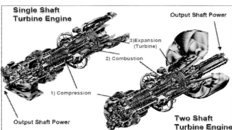
$ i r~g le $1h~ft 'TurbiA~ Engir~~
Expansion (Turbme)
OIUtp.l.\lt She~ Pcwer
T-w~ Sh~ft
Turb~ne