Investigation of Correlation of Broadband UVA Reflection
1to Broadband Visible Reflection for a Variety of Surfaces
2in the Built Environment
34
Joanna Turner*1, Alfio V Parisi1
5
1
Faculty of Health, Engineering and Sciences, University of Southern Queensland, Toowoomba,
6
QLD, Australia.
7
8
*Corresponding author (joanna.turner@usq.edu.au)
9
10 11
12 13
14
Summary of Declaration
15
Declaration of Interests: None
Abstract
18
UVA radiation (320-400 nm) exposure is linked to detrimental health effects, including DNA damage,
19
eye damage and impacts on immune suppression. Occupational exposure to UVA radiation could
20
increase the risk of developing such health effects, through increased exposure from reflective
21
surfaces. A range of surfaces have been investigated for broadband (from spectral) UVA and visible
22
reflectance, from horizontal, inclined and vertical orientations. A selection of this data has been
23
presented graphically. Non-metallic and coated metallic surfaces were shown to have low UVA
24
broadband reflectance (<0.20) compared to some metallic surfaces UVA broadband reflectance
(0.1-25
0.5). Uncoated metallic surfaces can use UVA reflectance as a function of visible reflectance,
26
however non-coated metallic surfaces have no similar function. The metallic surface type data were
27
used to correlate UVA broadband reflectance to visible broadband reflectance and a model developed
28
to express UVA broadband as a function of visible reflectance. The model for zinc aluminium coated
29
steel is a linear regression, with UVA reflectance ranging from 0.09 to 0.46 and visible reflectance
30
ranging from 0.05 to 0.57, with an R2 of 0.95. The reflective coefficients used to create the model
31
were produced on a solar zenith angle (SZA) range of 18°- 70.5°. The model was tested on a different
32
dataset with a SZA range of 5.7°- 62.9° on clear days and was shown to have reasonable results with
33
an RMSE of 0.049 for prediction of UVA reflectance from visible reflectance allowing prediction of
34
the UVA reflectance from the visible reflectance for this surface type.
35
36 37
38
Keywords:
39
UVA radiation, visible radiation, reflectance, model, specular, zinc aluminium steel
40 41
1.0 Introduction
43 44
Quantification of solar radiation reflectance within the built environment is very important for a range
45
of issues in the biosphere. Ultraviolet (UV) radiation reflectance contributes to increased risk of
46
certain types of skin cancer [1-3] by increasing UV exposure to outdoor workers, while thermal and
47
infrared radiation reflectance contributes to heat islands and energy balance issues at the building
48
level through to urban canyons [4, 5]. Visible radiation reflectance is important due to potential
49
distractions through glare, and there is an identifiable lack of regulation surrounding both visible
50
reflection and thermal reflection, specifically due to uncontrolled reflections that could cause damage
51
via human distraction or focused thermal reflection [6]. The biological impact of UV radiation on
52
humans in the biosphere, correlated with quantification of UV reflectance is slowly increasing,
53
however the ability to measure UV reflection is not always simple, given it mostly requires more
54
specialised equipment. Research has been done previously to correlate calculation of UV irradiance
55
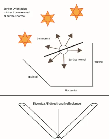
incident at the earth’s surface to the remaining terrestrial solar irradiance spectrum, by using ratios of
56
separate components of visible spectra, and infrared and global solar terrestrial irradiance spectra [7,
57
8]. The authors propose that it should be possible that UV reflectance could be predicted from visible
58
reflectance for some surface types. A study that characterises UV, visible and infrared reflectance has
59
been carried out by Berdahl and Bretz [9], but only total solar reflectance and thermal emittance are
60
correlated in this study. To the authors’ knowledge, there is no research yet that seeks to combine
61
information about proportionality between UV reflectance and visible reflectance directly in the built
62
environment.
63
Research conducted prior to 1950, shows that reflectance from surfaces has been measured for metals
64
used in daylighting or germicidal studies [10-17]. Research starting from 1925, but mostly from more
65
recent decades, provides albedo measurement from natural and built surfaces measured in the
66
broadband [18-25] or spectrally [26-31]. Reflectance of roofing materials have been documented, but
67
only for horizontal orientations or else conducted in the lab [32, 33]. In the last decade, the authors
68
have investigated reflectance from non-horizontal surfaces in the built environment (in the field) to
69
compare to horizontal surfaces [34-38]. The reflectance from primarily vertical surfaces raised issues
70
with terminology, such as the usage of reflectance versus albedo. The definition of albedo is defined
71
as the fraction of incident sunlight that a surface reflects [39] however in many fields, the definition of
72
albedo has been understood as the ratio of the up-welling reflected irradiance to down-welling incident
73
irradiance, sometimes called the surface albedo (for remote sensing or similar fields) or hemispherical
74
albedo (in planetary photometry). Hapke [40] provides several definitions for albedo and reflectance.
75
The latter definition of albedo provided above does not entail a measurement that is appropriate for
76
vertical surfaces. Turner and Parisi [34] show that using down-welling irradiance (all irradiance
77
incident from a hemispherical range of 180°) created artificially inflated reflectance values due to the
orientation of the surface (vertical) and the position of the sensor (with non-sun normal
79
measurements). Reflectance ratios exceeded the maximum of 1.0 reflectance using the albedo
80
definition of up-welling and down-welling irradiances, when measured in the field. In order to
81
compare horizontal reflectance with vertical reflectance, measurements were made by taking incident
82
irradiance from the direction of the sun with the sensor normal to the solar position. According to
83
Hapke [41] this is called bidirectional reflectance and accounts for angle of incident irradiance. In past
84
research conducted, most researchers have used down-welling measurements in their calculation of
85
albedo. This paper will focus on the use of bidirectional reflectance, and will hereafter be referred to
86
as reflectance for this study. Figure 1 (a) and (b) provide visual illustration of albedo and reflectance.
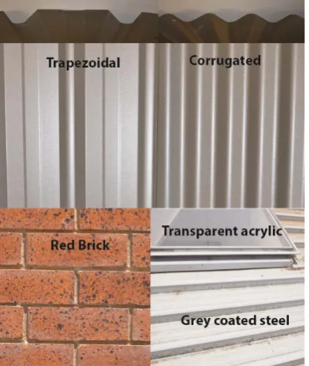
87
88
Figure 1- (a) albedo, as defined by the ratio of upwelling to downwelling irradiance. This can also
89
be referred to as bi-hemispherical reflectance defined by Hapke [41]
[image:4.595.72.286.250.472.2]91
Figure 1 - (b) reflectance as defined by the ratio of the reflected irradiance to incident irradiance
92
from a surface, which is dependent on angle of incidence and orientation of the surface (top
93
image).The sensor is rotated to be normal to sun and surface. Hapke [41] similarly describes this
94
as bidirectional reflectance, or biconical reflectance which implies a collimated beam of radiation
95
(bottom image).
96
Reflectance and albedo are strongly dependent on the surface type, and measured reflectance will
97
include different reflection characteristics of the surface, such as diffuse reflection (Lambertian
98
reflection), specular reflection (Fresnel reflection) or more commonly, some combination of both
99
diffuse and specular reflection. Coakley states that [39] it is assumed that surfaces reflect
100
isotropically (evenly and in all directions) which thus means that the incident irradiance has no effect
101
on the resultant reflectance and are therefore a Lambertian surface. Some natural surfaces can be
102
assumed to be an approximate Lambertian surface, but many surfaces, both natural and built, tend to
103
show variation of reflectance dependent on the incident irradiance angle. Previous work has already
104
shown a number of building materials reflect anisotropically, and therefore indicates the surfaces are
105
not predominantly Lambertian [34, 35]. In computer modelling studies of reflectance from surface,
106
bidirectional reflectance is more pronounced on specular surfaces compared to diffuse surfaces with
107
the difference described using clear spikes or lobes observed [42]. However Hapke [41] indicates that
108
descriptors such as directional, conical or hemispherical are more appropriate in understanding
109
reflectance which can describe both the incident and reflected radiation more accurately (hence
“bi-110
directional” describes highly collimated radiation source and reflection). Research also shows that
111
particle size of the surface controls the amount of specular or diffuse reflectance from a surface, with
112
the larger the particle with respect to wavelength, the more diffuse the reflectance becomes [43].
113
Therefore the more smooth a material, the smaller the surface particles should be and hence more
114
likely to produce specular reflection. Turner and Parisi’s [37] work on change in UV exposure due to
[image:5.595.75.286.75.340.2]surface reflectance suggests that variation in exposure to body site is due to the directional nature of
116
reflectance from specific built surface types.
117
Very little work has been conducted on broadband UVA (320-400 nm) reflectance, where UVA
118
reflectance measurement normally occur as part of a larger spectral measurement [26-30] or measured
119
reflectance at a large distance from a surface [44, 45] rather than in close proximity (defined as within
120
1 metre of a surface for this study). UVA radiation comprises 6.3% of the total solar spectrum outside
121
the earth’s atmosphere [46] and undergoes much less attenuation compared to UVB radiation (280
122
nm-320 nm), making up to 95% of all terrestrial solar UV radiation [47]. Within the region of the
123
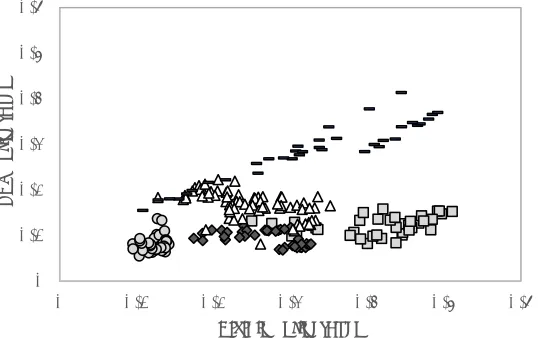
solar spectrum, UVA radiation and visible radiation are the most similar and located consecutively
124
within the same area of the solar spectrum. When this is combined with the reduced amount of
125
attenuation of UVA in the atmosphere, it means the two areas of the spectrum will be the most likely
126
to show comparable features and will hopefully provide an example for extension into future studies.
127
Whilst UVA radiation is less biologically effective than UVB radiation at causing detrimental impacts
128
(erythema and skin cancer), UVA radiation is also implicated in other health processes due to its
129
ability to penetrate deeper into skin, eyes and other biological surfaces. Damage caused by UVA
130
includes damage to DNA and the eye [48] and is potentially involved in the processes of immune
131
suppression [47]. Occupational exposure is linked to increased risk of developing skin cancer [1, 3],
132
therefore increased exposure to UVA reflectance could increase risk in all of the detrimental
133
biological effects described. Increased UVA exposure due to reflective surfaces therefore needs to be
134
explored and determining alternative methods to measure it may assist in reducing occupational UVA
135
exposure. This research consists of two parts: (a) investigation of UVA broadband reflection from
136
materials in the built environment that can influence occupational exposure and (b) investigation of
137
the possibility of predicting UVA broadband reflection from broadband visible radiation reflection.
138
139
2.0 Methodology
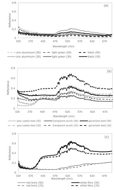
140
Reflectance measurements were made using the techniques outlined in [34] which use sun normal
141
measurements to replace down-welling irradiance measurements, and surface normal measurements
142
to determine reflectance from horizontal and non-horizontal surfaces with the sensor located at 0.5 m
143
from the surface (orientations as indicated in Figure 1 b) Measurements were made on a range of
144
surfaces at the University of Southern Queensland, Toowoomba (27.5°S, 151.9°E). The main surface
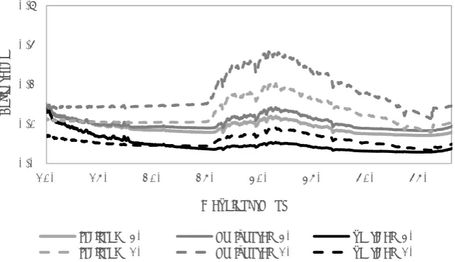
145
investigated was zinc aluminium coated steel with a trapezoidal profile, which is a commonly used
146
building material in Australia. Aluminium [9], zinc and steel [11] are known reflectors of UV
147
radiation. Most metal surfaces measured had a trapezoidal profile, while an additional similar surface
148
type had a corrugated profile. The remaining surfaces were made up of trapezoidal profile steel
149
sheeting with a coloured paint coating (multiple colours). Further surfaces investigated include red
brick, white painted fibro board, galvanised steel and some non-structural based surfaces such as
151
transparent plastic. An image of some of the surfaces is provided in Figure 2.
152
[image:7.595.73.295.118.381.2]153
Figure 2 - Example of some surface types investigated.
154
The zinc aluminium and paint coated steel sheets were measured on horizontal, vertical and inclined
155
(35° from the horizontal) orientations with all surfaces aligned to face towards the north, on clear days
156
or partially cloudy days with the sun not obscured during measurement, and no shading on the
157
reflective surface from the sensor. The remaining surfaces were measured from vertical, horizontal or
158
inclined surfaces that were located in the local area depending on existing structures. For example,
159
both the red brick and white painted fibro were only found in vertical orientations. The measurements
160
were made between 2008 and 2012 with the data collected using a USB4000 Plug-and-Play Miniature
161
fibre optic spectrometer (Ocean Optics, Inc.) from 300 nm to 700 nm in 0.2 nm steps, via an optic
162
fibre and cosine corrector with a 180° field of view. The signal to noise ratio below 300 nm is poor,
163
however given the solar terrestrial spectrum recorded at the earth’s surface does not continue much
164
lower than 300 nm due to absorption in the atmosphere and that this project focuses on the UVA
165
radiation, this poses no issue to the data collected for this project. The USB4000 spectrometer has a
166
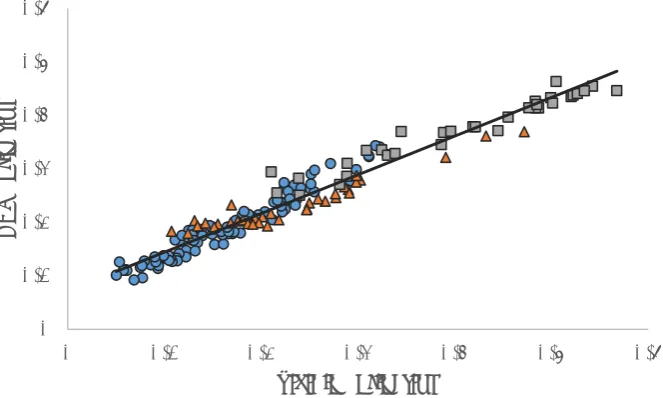
600 line blazed grating, a blaze wavelength of 400 nm and an opening slit of 25 µm. Each
167
measurement is made with a data capture time of 20 ms and averaged from 20 scans. The USB4000
168
spectrometer was initially calibrated to a NIST traceable standard from 200 nm to 800 nm. UV
169
measurements obtained using the USB4000 were then calibrated from 300 nm to 400 nm to a
170
scanning spectroradiometer (model DTM 300; Bentham Instruments, Reading UK) located at the
171
University of Southern Queensland (Toowoomba, Australia) which is traceable to the National
Physical Laboratory, UK. The measurements made by the calibrated USB4000 have an uncertainty of
173
approximately ±10% across the UV spectrum and entire range of SZA. It is expected that visible
174
measurements would have a minimum uncertainty of ±10%.
175
The data collected are spectral in nature, therefore the total broadband UVA reflectance and
176
broadband visible reflectance, after calibration, were calculated by integrating across the ranges of
177
320 nm to 400 nm, and 400 nm to 700 nm respectively for UVA and visible radiation for each
178
reflective surface and associated sun normal measurement, then calculating the reflectance by taking
179
the ratio of the reflected broadband irradiance to the sun normal broadband irradiance as expressed in
180
the following equation:
181
182
Where is the broadband reflectance, is the sun normal irradiance, and is the reflected
183
irradiance from the surface measured.
184
Reflected measurements were taken in succession after the sun normal measurements, with less than
185
a minute between each measurement. Therefore the reflected irradiance measurements occur within
186
one degree of SZA of the incident irradiance measurement. As the instrument records both UV and
187
visible irradiance in the same measurement, matching UVA to visible reflection for SZA is
188
straightforward. Data for each surface type and orientation were compiled for review. After reviewing
189
the data, surface types were selected to determine if visible broadband reflection could be used to
190
predict UVA broadband reflection. The selected surface type was zinc aluminium trapezoidal due to
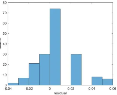
191
there being a suitable spread of data available for this surface type, across different orientations, as
192
well as the results found from the initial survey of data. From previous research, it is also suspected
193
that the surface is dominated by specular reflection, despite not appearing to be a specular surface
194
(mirror like) [43]. It is possible that a surface can still behave like a specular reflector in a non-visible
195
spectrum despite not appearing to be “mirror” like to the eye.
196
Data collected from 2008 to 2010 was used to generate the model to predict UVA reflection from
197
visible reflection and data collected from 2011 to 2012 were used to test the fit of the model.
198
Residuals and root mean square error (RMSE) were calculated to determine best fit, along with the
199
relative RMSE (rRMSE) which is defined as the ratio of the RMSE to the mean of the model result. It
200
is also useful here to comment regarding reflectance measurement within the UVB spectrum. The
201
equipment is capable of providing reflectance within the UVB spectrum down to 300nm without
202
significant signal-to-noise issues, however, at these wavelengths, the total irradiance reaching the
203
earth’s surface is small while showing correspondingly high reflectance. Spectral reflectance has been
204
previously shown to be relatively high [36] at wavelengths below 320nm. However, the focus within
this article is on the UVA and visible spectra, and therefore the data from 300nm to 320 nm is not
206
provided here.
207
208
3.0 Results
209
Figure 3 shows the comparison of UVA reflectance to visible reflectance for zinc aluminium
210
trapezoidal (n=398) and zinc aluminium corrugated surface types (n = 87). There is not enough zinc
211
aluminium corrugated data to test for an appropriate statistical comparison, however Figure 3 shows
212
that when producing a scatter plot of UVA broadband reflectance with respect to visible broadband
213
reflectance, there is definitely a strong similarity in the characterisation of the surface types. It appears
214
that the profile of the surface does not significantly change the reflectance characteristics provided the
215
surface is made of the same material. Turner [49] has further data analysis from spectral analysis
216
which confirms lack of significant difference between reflectance for profile types.
217
Figure 4 presents the data collected for metal surfaces only (n = 772). Three surface types have been
218
previously investigated for influence to human exposure (zinc aluminium steel, pale green coated
219
steel and cream coated steel) [37, 49], and have been plotted separately to the remaining types since
220
there is significantly more data available in these surface types compared to dark coloured paint
221
coated steel and light coloured paint coated steel. The dark coloured paint coated steel includes black,
222
blue, red and green – the latter colours all in dark shades. The light coloured paint coated steel
223
consists of beige and a product coating called Insultec 4 (Insultec, Australia), which is a white
224
coloured thermal radiation reflecting paint.
225
Figure 5 presents data collected from surfaces in the built environment from existing structures. The
226
data collected from the red brick surface and the white painted fibro surface are for vertical structures
227
with no inclined or horizontal features made out of the same surface material. The grey coated steel
228
was located on the rooftop of a building at the University as a roofing surface. The thick transparent
229
acrylic was also located on the roof. The grey paint coated steel was in a horizontal orientation only,
230
while the thick transparent acrylic was featured in a skylight on the roof, with an inclination of
231
approximately 45° to the horizontal. The galvanised steel (galvanised is normally understood to be a
232
coating predominantly made with zinc) was very shiny to look at and therefore highly reflective in the
233
visible spectrum, and was inclined at a small angle to the horizontal. The galvanised steel was part of
234
a structure located on the top of the building near the skylight and roof surface.
236
Figure 3 - Plot of UVA broadband reflectance with respect to visible broadband reflectance for zinc
237
aluminium trapezoidal (x) surface (all orientations) and zinc aluminium corrugated (o) for all
238
surface orientations.
239
[image:10.595.80.363.304.459.2]240
Figure 4 - UVA broadband reflectance with respect to visible broadband reflectance for metal
241
surfaces of all profile types (trapezoidal and corrugated) for dark colour paint coated (square ),
242
light coloured paint coated (circle ), zinc aluminium (diamond), cream paint coated (triangle ∆)
243
and pale green paint coated (-).
244
245
Figure 5 - UVA broadband reflectance with respect to visible broadband reflectance for white
246
painted fibro board (square ), red brick (circle ), grey paint coated steel (diamond), thick
247
transparent acrylic (triangle ∆) and galvanised steel (dash -).
248
0.0 0.1 0.2 0.3 0.4 0.5 0.6
0.0 0.2 0.4 0.6 0.8
UVA refl
ectance
Visible reflectance
0.0 0.1 0.2 0.3 0.4 0.5 0.6
0.0 0.1 0.2 0.3 0.4 0.5 0.6 0.7
UVA refl
ectance
Visible reflectance
0 0.1 0.2 0.3 0.4 0.5 0.6
0 0.1 0.2 0.3 0.4 0.5 0.6
UVA refl
ectance
[image:10.595.88.357.542.711.2]Figures 6 (a) and 6 (b) demonstrate the spectral reflectance of a variety of the surface types
249
investigated, for reflectance that has been measured at about 50° SZA and 30°SZA. Figure 6 (c)
250
shows reflectance measured at approximately 65-70° SZA and 50° SZA as the data was collected on
251
days with a low SZA range.
252
253
254
255
0 0.2 0.4 0.6 0.8
320 370 420 470 520 570 620 670
Ref
lectance
Wavelength (nm)
(a)
zinc aluminium (50) light green (50) black (50)
zinc aluminium (30) light green (30) black (30)
0 0.2 0.4 0.6 0.8
320 370 420 470 520 570 620 670
Ref
lectance
Wavelength (nm)
(b)
grey coated steel (50) transparent acrylic (50) galvanised steel (50)
grey coated steel (30) transparent acrylic (30) galvanised steel (30)
0 0.2 0.4 0.6 0.8
320 370 420 470 520 570 620 670
Ref
lectance
Wavelength (nm)
(c)
red brick (50) white fibro (50)
[image:11.595.59.432.149.769.2]Figure 6 - (a) Spectral reflectance for vertical trapezoidal surfaces at two different solar zenith
256
angles (b & c) Spectral reflectance from local building materials in existing structures at the
257
different SZA shown in brackets
258
Figure 6 provides spectral information about the behaviour of reflectance from a surface with respect
259
to SZA. From the figure it can be observed that for the surfaces in Figure 6a, the UVA reflectance
260
over the waveband decreases when SZA decreases, whereas the visible reflectance over the waveband
261
increases. In Figure 6b, grey coated steel and transparent acrylic decrease UVA spectral reflectance
262
with SZA, whereas the visible spectral reflectance increases. However, galvanised steel increases with
263
decreased SZA for both UVA spectral reflectance and visible spectral reflectance. Figure 6c shows
264
that UVA spectral reflectance does not vary significantly during a decrease in SZA, whereas the
265
visible spectral reflectance does increase for white painted fibro. Red brick appears to remain the
266
same for the UVA spectral reflectance and most of the visible spectral reflectance.
267
From this presented information, a general assessment can be made about what mechanism might be
268
contributing to the relationships presented in Figures 4 and 5 for broadband reflectance in the UVA
269
and visible spectra. In Figure 4, zinc aluminium steel shows that as UVA broadband reflectance
270
increases overall, so too does visible broadband reflectance. We can also observe in Figure 6a, that the
271
UVA spectrum shows higher reflectance in the shorter UVA wavelengths at higher SZA than the
272
longer UVA wavelengths, but with an increase in SZA, the UVA reflectance becomes more consistent
273
across the spectrum. As there is more prevalence of longer UVA wavelengths in the atmosphere
274
compared to shorter UVA wavelengths, the incident irradiance on the measured surface thus accounts
275
for the change in proportion of longer to shorter UVA wavelengths. For the paint coated steel
276
surfaces, we can see that the UVA broadband reflectance does not increase with visible broadband
277
reflectance in Figure 4. This could be due to the nature of the paint coating, however it is interesting
278
that the black coated surface shows an increase in visible spectral reflectance. The black paint coated
279
surface appears shiny when in use from certain angles of view, more so than the pale green coated
280
surface. This could suggest that the black paint coating may consist of smaller particles or a reduced
281
layer of particles on the coated steel. However, as black is a good absorber of thermal energy and is
282
not always desirable for use in common building practice, the reflectance properties within the visible
283
or the UVA spectra are unlikely to be as useful or practical compared to the more commonly used
284
surface types. In Figure 5, galvanised steel shows a similar relationship between UVA broadband
285
reflectance and visible broadband reflectance as compared to zinc aluminium steel. It is also notable
286
that the surfaces that have already been previously identified as more specular reflecting surfaces than
287
the paint coated surfaces, show a potential linear regression relationship between UVA broadband
288
reflectance and visible broadband reflectance. On consideration of the spectral nature of the
289
reflectance of the galvanised and zinc aluminium steel surfaces, we can observe that the spectral
290
reflectance tends towards a more consistent or even reflectance across both spectra. This then suggests
291
that predominantly specular reflecting surfaces are more likely to have a predictive relationship
between the UVA reflectance and the visible broadband reflectance. Therefore, the zinc aluminium
293
steel surface has been used to investigate a model to predict UVA broadband reflectance.
294
295
3.1 Predictive model for zinc aluminium surfaces
296
The following section focuses on data collected for the zinc aluminium trapezoidal sheet surface. The
297
data from 2008 to 2010 were collected in May 2008, October 2008, April 2009, August and October
298
2010 with a total of 209 measurements made from vertical, inclined and horizontal surface
299
measurements with a SZA range from 14.0° to 70.5°. Figure 7 shows the data according to surface
300
orientation (vertical, horizontal and inclined) and displays for all data included in this set, with the
301
regression line of best fit 0.7242 0.0695 and 0.91. Here, is the UVA broadband
302
reflectance and is the visible broadband reflectance. The broadband reflectance ranges are 0.09 -
303
0.46 for UVA reflectance and 0.05 - 0.57 for visible reflectance.
304
[image:13.595.91.420.332.584.2]305
Figure 7 – Broadband UVA reflection to visible reflection, for each surface orientation of vertical
306
(circles ), horizontal (triangles ∆) and inclined (squares ). SZA ranges are >60 (blue), 50-59.9
307
(orange), 40-49.9 (grey), 30-39.9 (yellow), 20-29.9 (purple) and <20 (green). Trend line of all
308
data (black unbroken line) and one to one line (grey unbroken line).
309
In Figure 7, there is data that does not fit the regression line particularly well. This data is from
310
October 2008 from a vertical surface only, and shows an unusual spread that appears to oppose the
311
general trend of the data. It appear to look more like data presented in Figure 5 for the red brick. The
312
data of poor fit is mostly found to have a SZA of less than 20° with one or two outliers in 30-39.9°
313
and 40-49.9 It was considered whether the smaller SZA, might contribute to an incident angle that
314
behaves more like a grazing angle. A grazing angle is either a very large or very small incident angle,
315
0.0 0.1 0.2 0.3 0.4 0.5 0.6
0.0 0.1 0.2 0.3 0.4 0.5 0.6
UVA reflectance
depending on whether it is measured from the horizontal or the normal of the surface. Grazing angle
316
reflectance can produce very high reflectance coefficients. However, these broadband reflectance
317
values are fairly low. The other possibility is that given the directional nature of the reflectance
318
measurement, the sensor may not capture the total reflected irradiance at these incident angles. A
319
preview of the 2011 and 2012 data shows that SZA smaller than 20° do not show the same poor fit to
320
a regression line as the data shown in Figure 7. Therefore the October 2008 data were removed in case
321
of other confounding errors that are not yet apparent. The removal of the data adjusted the line of
322
regression to 0.7239 0.0718 with a correlation of 0.95. The refined data is shown in
323
Figure 8 with respect to surface orientation. The total SZA range is not affected by removing this data,
324
with a range of 18°-70.5° with a total of 171 data values. Figure 9 shows the SZA spread associated
325
with the data for both the original data set (Figure 7) and the refined data set (Figure 9). The range of
326
reflection coefficients remains unchanged, with UVA reflection coefficients of 0.09 - 0.46 and visible
327
reflection coefficients of 0.05 - 0.57.
328
[image:14.595.89.421.334.533.2]329
Figure 8 - Refined data with regression model of data. UVA reflection to visible reflection matched
330
for SZA, for each surface orientation of vertical (circles), horizontal (triangles) and inclined
331
(squares).
332
333
0 0.1 0.2 0.3 0.4 0.5 0.6
0 0.1 0.2 0.3 0.4 0.5 0.6
UVA reflection
334
Figure 9 – (a) Histogram of SZA range for 209 data values used to create model (minimum of 14°
335
and maximum of 70.5°) (b) Histogram of SZA range for 171 data values used to create model
336
(minimum of 18° and maximum of 70.5°).
337
Each of the regression models presented here were tested and validated using data collected in
338
September 2011 and January 2012 that had a total of 178 data values, with a SZA range of 5.7° to
339
62.9°. The residuals of each regression model were reviewed. Initially the RMSE of the refined data
340
were shown to be greater than using a model with the included October 2008 data, which was
341
surprising. However, on closer inspection of the residuals for each version of the model, it was found
342
that there was some bias in both models by means of overestimating UVA broadband reflectance from
343
visible broadband reflectance. Using the residuals as a guide to adjust each model, it was found that
344
the best model to predict data were 0.7239 0.0518 which is created from the model that did
345
not include the October 2008 data. The RMSE for this model was calculated as 0.049. The calculated
346
RMSE and rRMSE’s for each model type is provided in Table 1. Figure 10 shows the data used to
347
validate the model and the refined model, while Figure 11 provides information about the residuals
348
from the model.
[image:15.595.90.504.73.239.2]349
Table 1 - RMSE, rRMSE for models devised to predict UVA reflection from visible reflection.
350
Model RMSE rRMSE
All data
0.7242 0.0695 0.188 0.69
Refined data
0.7239 0.0718 0.217 0.54
All data revised
0.7242 0.0595 0.054 0.21
Refined data revised
[image:15.595.72.413.549.664.2]351
[image:16.595.94.410.98.300.2]352
Figure 10 - Validation data from 2011 and 2012 for surface orientation of vertical (circles),
353
horizontal (triangles) and inclined (squares) and associated predicted values from refined model
354
(line) for zinc aluminium surfaces.
355 356
357
Figure 11 - Histogram of residuals for the model used to predict UVA reflection from visible
358
reflection.
359
360
4.0 Discussion
361
The results show that zinc aluminium coated steel with a trapezoidal profile has a UVA broadband
362
reflectance which can be estimated using a simple regression model based on visible broadband
363
reflectance. In general, we can make a statement regarding UVA broadband reflectance from built
364
materials with respect to visible broadband reflectance. Non-metallic surfaces and paint coated
365
metallic surfaces do not show UVA broadband reflectance as a function of visible broadband
366
reflectance. The reflectance values are in general 0.2 or below. While this will still contribute to UVA
367
0.0 0.1 0.2 0.3 0.4 0.5 0.6
0.0 0.1 0.2 0.3 0.4 0.5 0.6 0.7
UVA refl
ecti
on
[image:16.595.88.284.392.551.2]exposure on a nearby person, it is currently unknown if this reflectance value would cause a
368
significant increase to the overall UV exposure received. However, for individuals that work near
369
metallic shiny surfaces, if visible reflectance is high, UVA reflectance will also be high. In turn this
370
contributes to an increase in UVA exposure. The ability to predict UVA broadband reflectance from
371
visible reflectance means that outdoor workers are able to better assess their surrounding work area
372
for increased UVA hazards. The limitations to this model are that it is only appropriate for clear sky
373
days or when the sun is not obscured on partially cloudy days, and is only relevant to uncoated
374
metallic surfaces. If the sun is obscured, the reflectance is affected by the reduction of direct
375
irradiance on the reflective surface. This is already evident by the different spectral reflectance for
376
changing SZA. However, it appears that for different SZA ranges (Figures 7, 8 and 9), that large
377
broadband reflectance do not always depend on large SZA and vice versa. This is particularly relevant
378
for the vertical surface where SZA can be used as an approximate incident angle. To investigate this
379
further, the ratio of the UVA reflection to the visible reflection was plotted against SZA (Figure 12)
380
for zinc aluminium surface types (Figure 12a) and additionally a paint coated steel surface (Figure
381
12b).
382
Figure 12a shows that for zinc aluminium steel, the horizontal and inclined surface reflectance show a
383
slight trend in the proportion of UVA broadband reflectance to visible broadband reflectance
384
increasing at SZA of 40° or higher. The galvanised steel was also included in Figure 12a, and it also
385
shows this slight trend. For vertical surfaces (zinc aluminium steel surfaces) however, there is no
386
trend displayed. This may be due to the change in spectral reflectance over the day depending on the
387
surface type. Figure 13 provides two different SZA scans for three surface orientations of zinc
388
aluminium trapezoidal steel. For horizontal or inclined surface orientations, the UVA reflectance
389
remains the same or increases with decreasing SZA, as does the visible reflectance.
391
[image:18.595.82.389.74.450.2]392
Figure 12 – Ratio of UVA reflection to visible reflection with respect to SZA for (a) vertical (circles),
393
horizontal (triangles) and inclined (squares) surfaces for a zinc aluminium steel trapezoidal and
394
corrugated surfaces and for a gentle inclined galvanised steel surface (diamonds) and (b) pale
395
green coated trapezoidal surface.
396
397
Figure 13 - Spectral reflectance from zinc aluminium trapezoidal steel for two different SZA for
398
inclined, horizontal and vertical orientations.
399
0 0.5 1 1.5 2 2.5 3
0 20 40 60 80
UVA reflectance/Vis
ib
le
relfectance
Solar Zenith Angle (degrees)
(a)
0 0.5 1 1.5 2 2.5 3
0 20 40 60 80
UVA rel
fecti
on/Vi
sible
refl
ecti
on
Solar Zenith Angle (degrees)
(b)
0.0 0.2 0.4 0.6 0.8
320 370 420 470 520 570 620 670
Ref
lectance
Wavelength (nm)
inclined (50) horizontal (50) vertical (50)
[image:18.595.84.416.531.722.2]However, the UVA reflectance from the vertical surface is lower at the lower SZA while the
400
corresponding visible reflectance is higher. It is possible this inverse relationship between reflectance
401
for this particular vertical surface provides some explanation for lack of predictable relationship
402
between broadband UVA irradiance and broadband visible reflectance with respect to SZA shown in
403
Figure 12 (a). Despite this identified lack of relationship in Figure 12, Figure 7, 8 and 9 clearly show
404
that the broadband reflectance measured for UVA can be reasonably predicted from visible broadband
405
reflectance for vertical surfaces. Figure 12(b) was included to determine if paint coated surfaces
406
similarly show this effect, and Figure 14 displays the spectral reflectance for the same surface type
407
(pale green coated trapezoidal) for each orientation at different SZA.
408
[image:19.595.93.416.256.464.2]409
Figure 14 - Spectral reflectance from pale green paint coated trapezoidal steel for two different
410
SZA for inclined, horizontal and vertical orientations.
411
UVA reflectance in Figure 14 is lower at lower SZA, while the corresponding visible reflectance is
412
higher, except for the case of the vertical surface, which shows similar visible spectral reflectance for
413
both SZA. If vertical surfaces do not show a change in visible reflectance with SZA, then it may not
414
be possible to predict changes in UVA reflectance. However, reflectance from paint coated surfaces
415
tends to be much lower than zinc aluminium surfaces, and appear to have low influence on human
416
exposure [37, 38]. Therefore a predictive method of measuring UVA reflectance may not be
417
necessary for the paint coated surface types given their low influence on increasing UV exposure.
418
Comparison of non-painted metal surfaces to natural surfaces show a significant difference in
419
reflectance. Figure 15 shows the difference between reflectance of a natural surface (lawn or grass) as
420
measured by Feister and Grewe [26] compared to (not painted) zinc aluminium coated steel from this
421
study. Non painted metal surfaces have been shown to increase UV exposure [37, 38]. Therefore,
422
prediction of UVA reflectance from visible reflectance from non-painted surfaces with respect to low
423
reflectance from common natural surfaces may be useful for determining changes to UVA exposure.
424
0.0 0.2 0.4 0.6 0.8
320 370 420 470 520 570 620 670
Ref
lectance
Wavelength (nm)
inclined (50) horizontal (50) vertical (50)
425
Figure 15 - Spectral reflectance from horizontal zinc aluminium coated steel at two different SZA
426
and spectral reflectance from lawn and grass as measured by Feister and Grewe [26].
427
In terms of practical application for occupational workers, from the information presented in this
428
research, measurement devices such as a simple lux meter or light meter could be used to measure the
429
visible broadband reflectance of building materials, from which an estimation of the UVA reflectance
430
for zinc aluminium surfaces could be determined. Steps could then be taken to ensure adequate
431
personal protection is being used to prevent over exposure to UVA radiation.
432
Alternative opportunities for measuring visible reflectance can come from commonly used
433
technology. Many smartphones now have applications that can provide light measurements and may
434
also provide a method to estimate UVA reflectivity using the method developed in this research.
435
Additionally recent work with smartphones [50, 51] have been shown to be capable of measuring
436
UVA directly, which suggests the model in this paper may be able to be tested using different
437
equipment (such as smartphones) in the future. Smartphone types that have not been characterised by
438
the method used by Igoe et al., [51, 52] could be used to calculate UVA reflectance from visible
439
reflectivity coefficients using the model presented here. Furthermore, a smartphone application could
440
be developed that uses a smartphone’s internal sensors to measure UVA reflectivity, from the visible
441
reflection captured by the camera in the smartphone.
442
There is a number of future directions from which this work can progress, including determining if
443
there is a relationship between biologically weighted UVA and visible radiation, or determining if
444
there is a relationship between visible and UVB radiation reflectance. It is also important to
445
investigate other surface types, both man-made and natural, for any possible associated relationships
446
between UVA and visible reflection, particularly in the case of high coefficient reflecting surfaces.
447
The most highly desirable future direction would be to explore the relationship between biologically
448
weighted UV reflectance and biologically weighted visible weighted reflectance. For example, the
449
0.0 0.1 0.2 0.3 0.4 0.5 0.6 0.7 0.8 0.9 1.0
320 420 520 620 720
Ref
lectance
Wavelength (nm)
erythemal weighted UV reflectance could be compared to photopic weighted visible reflectance
450
(sensitivity of the human eye).
451
452
5.0 Conclusions
453
UVA radiation is associated with a number of biologically detrimental effects, and outdoor workers
454
are exposed to these effects when they are involved in outdoor occupational activities. Occupational
455
workers that need to work in areas of built materials that have high reflectivity in the UVA spectrum,
456
increase their risk of developing health concerns due to exposure to UVA radiation. This paper has
457
presented UVA and visible reflectance for a range of common building materials used in Australia.
458
Spectral and broadband reflectance was presented for the range of surface types. It was found that
459
non-metallic and some painted coated metallic surfaces had UVA broadband reflectance of less than
460
0.2 and will contribute to normal UV exposure through scattering from nearby surfaces. In contrast,
461
metallic surfaces without a coating could have relatively high UVA broadband reflectance, which can
462
be determined as a function of unweighted visible broadband reflectance and could potentially
463
increase a person’s UVA exposure significantly. The surface types that fit this model are steel coated
464
in aluminium and zinc, or just zinc. The model developed has an R2 of 0.95 and an RMSE of 0.049.
465
Since the reflective surface shows that reflectance can change with respect to SZA, a model can assist
466
the prediction of UVA reflectance to assist in determining personal protection.
467
6.0 Acknowledgements
470
The authors would like to thank the University of Southern Queensland for supporting this research.
471 472 473 7.0 References 474 475
1. Gies, H.P. and J. Wright, Measured solar ultraviolet radiation exposures of outdoor workers
476
in Queensland in the building and construction industry. Photochemistry and Photobiology,
477
2003. 78(4): p. 342-348.
478
2. Håkansson, N., et al., Occupational sunlight exposure and cancer incidence among Swedish
479
construction workers. Epidemiology, 2001. 12(5): p. 552-557.
480
3. Milon, A., et al., Effective exposure to solar UV in building workers: influence of local and
481
individual factors. Journal of Exposure Science and Environmental Epidemiology, 2007. 17:
482
p. 58-68.
483
4. Arnfield, A.J., Review: Two decades of urban climate research: a review of turbulence,
484
exchanges of energy and water, and the urban heat island. International Journal of
485
Climatology, 2003. 23: p. 1-26.
486
5. Fortuniak, K., Numerical estimation of the effective albedo of an urban canyon. Theoretical
487
and Applied Climatology, 2008. 91(1-4): p. 245-258.
488
6. Danks, R., J. Good, and R. Sinclair, Assessing reflected sunlight from building facades: A
489
literature review and proposed criteria. Building and Environment, 2016. 103: p. 193-202.
490
7. Escobedo, J., et al., Modeling hourly and daily fractions of UV, PAR, and NIR to global solar
491
radiation under various sky conditions at Botucatu, Brazil. Applied Energy, 2009. 86: p.
299-492
309.
493
8. Escobedo, J., et al., Ratios of UV, PAR and NIR components to global solar radiation
494
measured at Botucatu site in Brazil. Renewable Energy, 2011. 36: p. 169-178.
495
9. Berdahl, P. and S.E. Bretz, Preliminary survey of the solar reflectance of cool roofing
496
materials. Energy and Buildings, 1997. 25: p. 149-158.
497
10. Edwards, J.D., Aluminium reflectors. Transactions of the Illuminating Engineering Society,
498
1939. 34: p. 427-440.
499
11. Hulburt, E.O., The reflecting power of metals in the ultraviolet region of the spectrum.
500
Astrophysical Journal, 1915. 42(3): p. 205-230.
501
12. Luckiesh, M., Reflection and Transmission, in Applications of Germicidal, Erythemal and
502
Infrared Energy. 1946, D. Van Nostrand Company, Inc.: New York. p. 375-451.
503
13. Stutz, G.F.A., Observations of spectro-photometric measurements of paint vehicles and
504
pigments in the ultra-violet. Journal of the Franklin Institute, 1925. 200(1): p. 87-102.
505
14. Taylor, A.H., Reflection factors of various materials for visible and ultraviolet radiation.
506
Journal of the Optical Society of America, 1934. 24(7): p. 192-193.
507
15. Taylor, A.H., Light and ultraviolet reflection by various materials. Transactions of the
508
Illuminating Engineering Society, 1935. 30: p. 563-566.
509
16. Taylor, A.H., Ultraviolet reflectance characteristics of various materials. Illuminating
510
Engineering, 1941. 36: p. 927-930.
511
17. Wilcock, D.F. and W. Soller, Paints to reflect ultraviolet light. Industrial and Engineering
512
Chemistry, 1940. 32(11): p. 1446-1451.
513
18. Angstrom, A., The albedo of various surfaces of ground. Geografiska Annaler, 1925. 7: p.
514
323-342.
515
19. Diffey, B., et al., A portable instrument for measuring ground reflectance in the ultraviolet.
516
Photochemistry and Photobiology, 1995. 61(1): p. 68-70.
517
20. Heisler, G.M. and R.H. Grant, Ultraviolet radiation in urban ecosystems with consideration
518
of effects on human health. Urban Ecosystems, 2000. 4: p. 193-229.
21. ICNIRP, Protecting workers from ultraviolet radiation. 2007, International Commision on
520
Non-Ionising Radiation Protection.
521
22. Parisi, A.V., et al., Lifetime ultraviolet exposure estimates for selected population groups in
522
south-east Queensland. Physics in Medicine and Biology, 1999. 44: p. 2947-2953.
523
23. Reuder, J., et al., Investigations on the effect of high surface albedo on erythemally effective
524
UV irradiance: Results of a campaign at the Salar de Uyuni, Bolivia. Journal of
525
Photochemistry and Photobiology B: Biology, 2007. 87: p. 1-8.
526
24. Rosenthal, F.S., et al., The occular dose of ultraviolet radiation to outdoor workers.
527
Investigative Ophthalmology and Visual Science, 1988. 29(4): p. 649-656.
528
25. Sliney, D.H., Physical Factors in Cataractogenesis: ambient ultraviolet radiation and
529
temperature. Investigative Ophthalmology and Visual Science, 1986. 27(5): p. 781-790.
530
26. Feister, U. and R. Grewe, Spectral albedo measurements in the UV and visible region over
531
different types of surfaces. Photochemistry and Photobiology, 1995. 62(4): p. 736-744.
532
27. Lester, R.A. and A.V. Parisi, Spectral ultraviolet albedo of roofing surfaces and human facial
533
exposure. International Journal of Environmental Health Research, 2002. 12: p. 75-81.
534
28. Lin, C., C. Han, and C. Liu, A comparison of the albedo of Asian Building materials in visible
535
and UVB regions, in International Conference on Electric Technology and Civil Engineering
536
(ICETCE). 2011, IEEE: Lushan, China.
537
29. McKenzie, R.L., M. Kotkamp, and W. Ireland, Upwelling UV spectral irradiances and
538
surface albedo measurements at Lauder, New Zealand. Geophysical Research Letters, 1996.
539
23(14): p. 1757-1760.
540
30. Webb, A., et al., Airborne spectral measurements of surface reflectivity at ultraviolet and
541
visible wavelengths. Journal of Geophysical Research, 2000. 105(D4): p. 4945-4948.
542
31. Coulson, K.L. and D.W. Reynolds, The spectral reflectance of natural surfaces. Journal of
543
Applied Meteorology, 1971. 10(6): p. 1285-1295.
544
32. Kültür, S. and N. Türkeri, Assessment of long term solar reflectance performance of roof
545
coverings measured in laboratory and in field. Building and Environment, 2012. 48: p.
164-546
172.
547
33. Parker, D.S., et al. Laboratory testing of the reflectance properties of roofing materials.
548
Florida Solar Energy Center, 2000.
549
34. Turner, J. and A. Parisi, Improved method of ultraviolet radiation reflection measurement for
550
non-horizontal urban surfaces. Measurement Science & Technology, 2012. 23(4).
551
35. Turner, J. and A. Parisi, Ultraviolet Reflection Irradiances and Exposures in The Constructed
552
Environment For Horizontal, Vertical and Inclined Surfaces. Photochemistry and
553
Photobiology, 2013. 89(3): p. 730-736.
554
36. Turner, J., A. Parisi, and D. Turnbull, Reflected solar radiation from horizontal, vertical and
555
inclined surfaces: Ultraviolet and visible spectral and broadband behaviour due to solar
556
zenith angle, orientation and surface type. Journal of Photochemistry and Photobiology
B-557
Biology, 2008. 92(1): p. 29-37.
558
37. Turner, J. and A.V. Parisi, Measuring the influence of UV reflection from vertical metal
559
surfaces on humans. Photochemical & Photobiological Sciences, 2009. 8(1): p. 62-69.
560
38. Turner, J. and A.V. Parisi, Influence of reflected UV irradiance on occupational exposure
561
from combinations of reflective wall surfaces. Photochemical & Photobiological Sciences,
562
2013. 12(9): p. 1589-1595.
563
39. Coakley, J.A., Surface Reflectance and Albedo, in Encyclopedia of Atmospheric Sciences,
564
R.H. James, Editor. 2003, Academic Press: Oxford. p. 1914-1923.
565
40. Hapke, B., Integrated reflectances and planetary photometry, in Theory of reflectance and
566
emittance spectroscopy. 2012, Cambridge University Press: Cambridge, United Kingdom. p.
567
287-302.
568
41. Hapke, B., The bidirectional reflectance of a semi-infinite medium, in Theory of Reflectance
569
and Emittance Spectroscopy. 2012, Cambridge University Press: Cambridge, United
570
Kingdom. p. 180-220.
571
42. Nayar, S.K., K. Ikeuchi, and T. Kanade, Surface reflection: Physical and Geometrical
572
Perspectives. IEEE Transactions on Pattern Analysis and Machine Intelligence, 1991. 13(7):
573
p. 611-634.
43. Ahn, J.S., T.R. Hendricks, and I. Lee, Control of specular and diffuse reflection of light using
575
particle self-assembly at the polymer and metal interface. Advanced Functional Materials,
576
2007. 17: p. 3619-3625.
577
44. Rengarajan, G., et al., Albedo measurement system for UVA and the visible wavelength, in
578
Radiation Protection Dosimetry: Ultraviolet radiation exposure, measurement and
579
protection, A.F. McKinlay and M.H. Repacholi, Editors. 2000, Nuclear Technology
580
Publishing: Kent, UK. p. 197-199.
581
45. Weihs, P., et al., Measurements of the reflectivity in the ultraviolet and visible wavelength
582
range in a mountainous region, in Radiation Protection Dosimetry: Ultraviolet radiation
583
exposure, measurement and protection, A.F. McKinlay and M.H. Repacholi, Editors. 2000,
584
Nuclear Technology Publishing: Kent, UK. p. 193-195.
585
46. Frederick, J., H.E. Snell, and E.K. Haywood, Solar ultraviolet radiation at the earth's surface.
586
Photochemistry and Photobiology, 1989. 50(8): p. 443-450.
587
47. Wang, S.Q., et al., Ultraviolet A and melanoma: A review. Journal of American Academy of
588
Dermatology, 2001. 44(5): p. 837-846.
589
48. Barker, F., The Effects of UV-A upon the Eye, in Biological Responses to Ultraviolet A
590
Radiation: Second International Conference, F. Urbach, Editor. 1992, Valdenmar Publishing
591
Company: San Antonio, Texas. p. 273-280.
592
49. Turner, J., Ultraviolet radiation reflection: Characterisation, quantification and the resulting
593
effects, in Department of Biological and Physical Sciences. 2011, University of Southern
594
Queensland: Toowoomba, Australia. p. 314.
595
50. Igoe, D. and A. Parisi, Evaluation of a smartphone sensor to broadband and narrowband
596
Ultraviolet A radiation. Instrumentation Science and Technology, 2015. 43(3): p. 283-289.
597
51. Igoe, D., Development and characterisation of a modified smartphone camera for
598
determining UVA aerosol optical depth, in Faculty of Health Engineering and Sciences. 2013,
599
University of Southern Queensland.
600
52. Igoe, D. and A.V. Parisi, Broadband direct UVA irradiance measurement for clear skies
601
evaluated using a smartphone. Radiation Protection Dosimetry, 2015. 167(4): p. 485-489.
![Figure 1- (a) albedo, as defined by the ratio of upwelling to downwelling irradiance. This can also be referred to as bi-hemispherical reflectance defined by Hapke [41]](https://thumb-us.123doks.com/thumbv2/123dok_us/144970.22114/4.595.72.286.250.472/figure-defined-upwelling-downwelling-irradiance-referred-hemispherical-reflectance.webp)