Int. J. Electrochem. Sci., 11 (2016) 5490 – 5506, doi: 10.20964/2016.07.96
International Journal of
ELECTROCHEMICAL
SCIENCE
www.electrochemsci.orgBiocorrosion Control of Electroless Ni-Zn-P Coating Based on
Carbon Steel by the
Pseudomonas aeruginosa
Biofilm
Sahar A. Fadl-allah1,3,*, A.A. Montaser1,4, Sanaa M.F. Gad El-Rab2,5
1
Materials and Corrosion Lab (MCL), Faculty of Science, Taif University, Taif, KSA 2
Biotechnology Department, Faculty of Science, Taif University, Taif, KSA 3
Chemistry Department, Faculty of Science, Cairo University, Cairo, Egypt 4
Chemistry Department, Faculty of Science, Aswan University, Aswan, Egypt 5
Botany and Microbiology Department, Faculty of Science, Assuit University,71516 Assuit, Egypt *
E-mail: sahar.fadlallah@yahoo.com
Received: 2 April 2016 / Accepted: 1 May 2016 / Published: 4 June 2016
Pseudomonas aeruginosa (P. aeruginosa) is considered one of the most important microorganisms that show a strong trend to growth on the metal surface and promote the biofilm formation. The present study describes the effect of P. aeruginosa (ATCC9027) on the corrosion resistance of electroless nickel-zinc-phosphorous (Ni-Zn-P) alloy coating based on carbon steel C1018. The influence of aerobic bacteria P. aeruginosa on the corrosion behavior of C1018 and Ni-Zn-P alloy in artificial sea water was studied by dielectric spectroscopy. Scanning electron microscope, SEM, and energy dispersive X-ray surface analysis techniques were used to distinguish the morphology and chemical composition of the alloy coating surface before and after 28 days of immersion in a nutrient medium. Although, the presence of P. aeruginosa in sterile media reduce the value of the corrosion resistance of C1018 to 691Ω , but it rises the corrosion resistance of Ni-Zn-P alloy up to 28KΩ. Quantitative description of the power of the morphology of alloy coating on bacterial affection and biofilm construction was investigated by the plate-counting method. The free biofilm fraction electrode surface (1-Ɵ) was calculated for C1018 and Ni-Zn-P to be equal 4.016 and 0.3616, respectively. These results revealed that the antibacterial performance of the zinc alloy coating is better than the uncoated C1018 and it encourages the formation of passive biofilm protect carbon steel from biocorrosion.
Keywords: Carbon steel, Pseudomonas aeruginosa, Biocorrosion, Biofilm, Ni-Zn-P alloy, EIS, SEM/EDX.
1. INTRODUCTION
products contained in petroleum products from one place to another on the surface of the earth. One of the most important problems which faces carbon steel pipelines is the aggressive character of environment for instance seawater by salt and microbial nature, so the study of protecting carbon steel pipeline surface with a thick hard protective coat is therefore quite significative [1-3].
Due to the presence of microorganisms in the seawater that has been recognized to attach themselves to surfaces of pipeline networks and colonize, proliferate and finally form biofilm [4]. Biofilms are microbial populations from complex microbial structure collected of their metabolic products, cells and including extracellular polymeric substance (EPS). This composition creates changes in the electrochemical behavior at the surface of the metal and in the surrounding environment [5] and cause biocorrosion or microbiologically influenced corrosion (MIC) [6-8]. Different attack process at the metal-alloy interface will occur, such as the localized corrosion, general corrosion or corrosion inhibition due to the change in the electrochemical conditions that caused by microorganisms [9].
Industrial current progress directs the research to form a new generation of antibacterial cover, protect pipelines from hazardous effects of the microorganism through to put a stop to their growth. For example, the production of antibacterial coating intended for the relevance of petrochemical industries to provide safety and economic solution for biocorrosion issue [10,11]. After attachment of viable bacteria on the metallic surfaces and interfaces, bacteria colonization and biofilms are formed that may causes both corrosive and inhibitory actions and complex biofilm /protective film interactions [9].
Autocatalytic electroless Ni coatings is alternate simple method to produce a thin uniform layers have gotten attractiveness due to their excellent corrosion, wear and scratch resistance. The coating structure plays a vital role on its properties dependant on amount of P deposited. The coating property can be further enhanced by deposit in Ni-P matrix another one or more metallic elements as the same as Zn, Cu, Co, etc. [12]. The nickel ternary alloy coating is regarded as the most successful method to alter the physical and chemical properties of binary Ni–P alloy deposits [13–15]. The merging of Zn element into Ni–P matrix has great impact on the microstructure and mechanical properties of Ni-P coating [16]. Moreover, Ni–Zn–P coating has the best corrosion resistance in briny surrounding as electrochemical results indicated in the literature [16, 17].
Pseudomonas aeruginosa is the most abundant bacterial species present in industrial and seawaters and it is intimately involved in corrosion process and has been chosen the major colonist in the process of biofilm configuration. In addition P. aeruginosa is a harmful pathogen bacteria that can cause many respiratory diseases [18]. Pervious reports demonstrated that P. aeruginosa may release acids enhance the passivity breakdown and increase the corrosion rate of metals and alloy [19], or secrete EPS binding with the metal surface ions and may lead to shift the electrochemical behavior of the metal surface to noble direction [20]. Until now the mechanism governing the role of biofilm process remains unclear [21].
alloy coating was explored by using EIS measurements. Furthermore, SEM/EDX analysis was used to record the changes in the morphology and chemical composition of coating surfaces under different situation.
2. EXPERIMENTAL 2.1. Materials and solutions
Cylindrical - shaped commercial carbon steel coupons with 15mm thickness and 0.5cm hight from Armco (Part Number:CO1113770204120, C1018), Serial Number: 2524 were used. C1018 carbon steel (CS) is composed of 0.26wt%C, 0.46wt%Mn, 0.27wt%Si, 0.035wt%S, 0.11wt%Cr, 0.09wt%Ni, 0.01wt %P and 0.15wt %Cu with the remainder Fe. C1018 plate of 6 mm thickness was cut to 10 mm X 10 mm size coupons. Before every experiment, the coupons were mechanically polished using increasing better quality grades of silicon carbide papers from 400 up to 1200 grit. After polishing the coupons were ultrasonically agitated for 15 min and clean by immersion to pure ethanol for 1h.
2.2. Bath of Electroless deposition
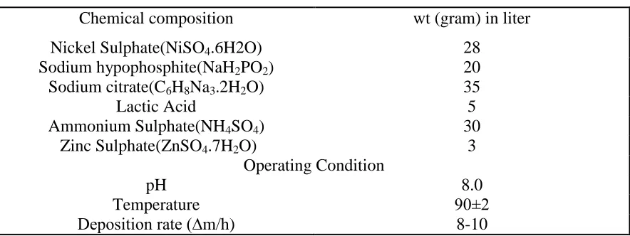
[image:3.596.78.520.494.660.2]The zinc ternary alloy coating was prepared from the sodium hypophosphite electrolyte bath by means of the chemical composition shown in Table1.
Table 1. The Experimental conditions to prepare the alloy coating.
Chemical composition wt (gram) in liter
Nickel Sulphate(NiSO4.6H2O) 28
Sodium hypophosphite(NaH2PO2) 20
Sodium citrate(C6H8Na3.2H2O) 35
Lactic Acid 5
Ammonium Sulphate(NH4SO4) 30
Zinc Sulphate(ZnSO4.7H2O) 3
Operating Condition
pH 8.0
Temperature 90±2
Deposition rate (∆m/h) 8-10
2.3. Surface Analysis Studies
The surface morphology and chemical composition of C1018 and Ni-Zn-P alloy coating samples were examined and investigated by scanning electron microscope, SEM, with energy dispersive X-ray spectra, EDX, analysis by JEOL-840 electron prop micro analyzer [23].
2.4. Electrochemical impedance spectroscopymeasurements
The corrosion resistance of the C1018 and Ni-Zn-P alloy coating was investigated in free artificial sea water (A) and in artificial sea water containing P. aeruginosa (B) solutions at room temperature. Dielectric spectroscopy which it’s known as electrochemical impedance spectroscopy, EIS, is a non-destructive responsive method which makes possible the detection of any transform occurring at the metal / solution interface. All EIS measurements were carried out using a potentiostat AUTOLAB (PGSTAT 30 with FRA modules, Ecochemie) in the same compartment three-electrode cell, which discussed previously. All EIS spectra were obtained by applying the open circuit potential at a frequency range of 10−1–105 Hz to evaluate the constancy of C1018 and Ni-Zn-P alloy coating in two electrolyte solutions [23]. The impedance spectrum is displayed as a Bode diagram (impedance modulus and phase angle vs. frequency) and Nyquist diagrams (Real impedance vs. imaginary impedance) [23]. From Bode & Nyquist plots, equivalent circuits that fit the experimental data were proposed. EIS outcomes were interpreted using a fitting procedure fit program ANOVA 1.8 for all the frequencies measured [23]. The standard used in estimating the quality of the fitting were evaluated with the minor chi-square value and the minor evaluation errors (in%) for all the machinery [23].
2.5. Microbial Study
2.5.1. Inoculums agriculture
The entire tests were carried out using a nutrient-rich simulated seawater-based medium. The medium consists of 23.476 g/l NaCl; 3.917 g/l Na2SO4; 0.192 g/l NaHCO3; 0.664 g/l KCl; 0.096 g/l KBr; 10.61 g/l MgCl2; 6H2O; 1.469 g/l CaCl2; 2H2O; 0.026 g/l H3BO3; 0.04 g/l SrCl2; 6H2O, 3 g/l bacteriological peptone and 1.5 g/l yeast take out from Oxoid, UK. The value of pH of the medium was adjusted to 7.2 ± 0.1 by NaOH solution, and untainted by autoclaving for 20 min at 121 °C at low pressure. The Pseudomonas aeruginosa ATCC 9027 (P. aeruginosa) strain was supplied by INCQS/FIOCRUZ, RJ, and Brazil. A new culture was refreshing from ice-up-dried ampoule, and associate cultured two time in 5 ml of nutrient broth media before use [23]. The bacterium was cultivated for 3 days in a 125 ml Erlenmeyer flask containing 20 ml of the new culture medium on a rotary shaker (15 °C, 175 RPM) after the recovery. A total of 20 ml of the cultured bacteria stored in a _
2.5.2. Electrochemical and surface study after cultivation of P.aeruginosa
Into 100 ml of the nutrient rich medium was fertilized by one ml of P.aeruginosa culture for 3 days in conical flasks. The flasks were covered with closure to prevent pollution. After sterilization, the prepared specimens were introduced into the inoculated medium. The flasks containing the metal specimens were kept in an incubator at 25 °C. To keep up the bacterial density at the steady-state growth phase throughout the study period, a renew mode of P.aeruginosa culture growth was employed, that is to say 75% medium was exhausted and put back with an equal amount of a fresh sterile medium each 7 days. C1018 and Ni-Zn-P alloy coating samples were get back from the inoculated medium after four weeks of immersion to study the electrochemical behavior and for surface analysis.
2.5.3. Follow up Bacterial Attachement
The full amount of bacterial attachment was looked into by the plate-counting method [23]. The rate of bacteria attachment in the simulated repository environment was confirmed by counting up analysis of the media after 1, 3, 7, 14, 21 and 28 days of immersion. For all experimental conditions two samples were used for CFUs evaluation. The samples were taken away from the medium, softly washed to remove stick on bacterial cells on the samples were diffused into15 ml sterile phosphate buffer (0.0425 g KH2PO4 and 0.190 g MgCl2 per liter) by forceful vortex mixing for 5 min. Successive dilution of the bacterial cell suspensions was prepared and 0.1 ml of each concentration was plated onto nutrient agar to hold up the development of bacteria. The plates were incubated for 24h and the numbers of colonies are calculated. Suggested practical cells on each specimen were calculated and expressed as colony forming units per square centimeter (CFU cm-2).
2.5.4. Biofim study
In our study the formation of biofilm was detected on uncoated C1018 and Ni-Zn-P alloy coating by SEM after the specimens recapture from the inoculated medium after 28 days of exposure. Furthermore, to appreciate the grade of deterioration under the biofilm, the specimens were immersed in a beaker with 100 ml of a 0.1 M EDTA solution [24, 25], and then ultrasonicated for 15 min in a Cole–Parme, USA bath with a frequency of 40–50 kHz to eliminate the corrosion products and the biofilm [25]. The samples were coated with gold by supptring method and examine with SEM. The location for SEM imaging were randomly chosen on the C1018 and Ni-Zn-P alloy coating surface to be representative of their total surfaces.
3. RESULTS AND DISCUSSION
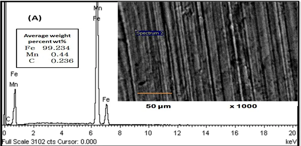
porous surface structure, Fig.1 (A). The results of the EDX analysis of the surface of C1018 confirm that the key elements present is Mn and Fe.
Figure 1. Surface Morphology and Chemical Composition of Carbon steel (A) and Ni-Zn-P alloy coating (B).
[image:6.596.53.546.132.372.2][image:7.596.54.545.131.365.2]
chemical composition of surface film confirmed by EDX analysis for Ni-Zn-P alloy coating and presented also in Fig. 1 (B), which support the deposition of Zn.
Figure 2. Surface Morphology Carbon steel C1018 (A) and Ni-Zn-P alloy coating (B) after 28 days of immersion in artificial seawater.
[image:7.596.51.550.423.715.2]
The high nickel content (78 wt.%) is confirmed the successful deposition of a good passive coat by the electroless method more than 15-20 wt.% nickel content formed by the conventional plating method [27]. The present analysis results confirm the fact that the electroless process can be used to produce a passive coat with lower zinc content that can replace Cd in sacrificial protecting underground petrochemical pipelines [27]. Also, the low iron 2.400 wt.% in Ni-Zn-P alloying coat referred to the good coating layer from Zn, Ni, and P species that formed via the present bath conditions.
[image:8.596.51.548.318.593.2]The surface morphology of C1018 and Ni-Zn-P alloy coating after immersion in sterile medium for 28 days is presented in Fig.2. From this figure we can note that complete corrosion failure of the surface is recorded for carbon steel C1018 without coating in sterile medium, while the passive Ni-Zn-P alloy coating can resist the damage and successfuly protect the surface of carbon steel from corrosion. This result reflects the ability of electroless Ni-Zn-P in corrosive environment.
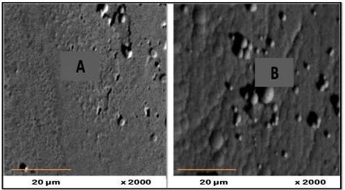
Figure 4. Surface Morphology of Carbon steel C1018 (A) and Ni-Zn-P alloy coating (B) after removal of biofilms.
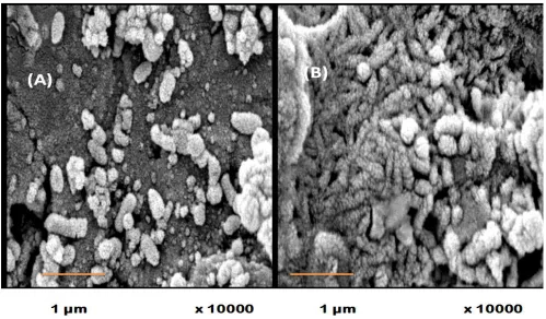
release acids [19]. The extensive biofilm formed on Ni-Zn-P alloy coating, we infer that the compact biofilm layer may provide extra protection to this alloy coating in seawater.
To make sure the effectivness of biofilm on the surface of C1018 and Ni-Zn-P alloy coating , the biofilm on both surfaces was removed according to the procedure that described in the experimental section and both surfaces was analysied by SEM.
[image:9.596.109.443.488.728.2]Fig. 4 shows that micro-pits were observed on the surface of C1018, Fig. 4 (A), while there are no absolute micro-pits on Ni-Zn-P alloy coating was observed after removing the biofilm layer, Fig.4 (B). Further very nice observation detected from Fig.4 (B) is that the cauliflower-like nodules Ni-Zn-P alloy coating was still intact after removing the biofilm. This result supports the result deduced from Fig.3, which illustrate that the thick biofilm layer formed on Ni-Zn-P alloy coat act as a protective anticorrosive auxiliaery coat [28]. The present results agreement with another further results that pointed to the existence of extra-cellular polymers (EPS) which extracted from the cells of bacteria and formed on the alloy surface. EPS retarded the corrosion process or impaired the protective nature of the alloy through the formation of passive layer from died cells [28]. The most predictable mechanisms by which bacteria cause an inhibition of corrosion are recognized to a decrease in the damage action of the medium at the metal-bulk solution interface throughout decreasing the acidity of the medium, or due to the formation of strong protective biofilms on the metal surface by the production of EPS with metal abilities and finally or due to decrease the cathodic reaction that results from the utilization of a cathodic electron acceptor by microbes [29, 30]. The thick biofilm layer composed of extracellular polymeric substance formed on Ni-Zn-P act as a defending layer, which falling the contact of the alloy surface to the exterior environment. Among the two types of the present samples, Ni-Zn-P alloying coat showed higher resistance due to the uniform compact of biofilm formation than the uncoated C1018 ones.
Figure 5. Pseudomonas aeruginosa colonies on broth-agar plates.
First Second Third Fourth
0 1x10⁹ 2x10⁹ 3x10⁹ 4x10⁹ 5x10⁹ 6x10⁹
Colony F
orming Un
its (CF
U)
Weeks (days)
Bacterial Biofilm On C1018
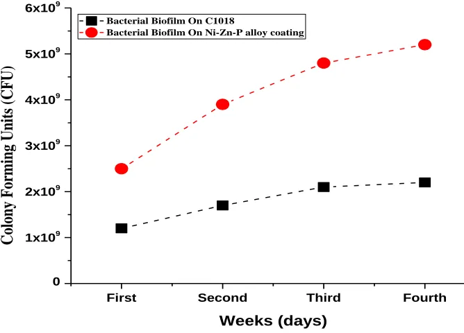
In the present work, the P. aeruginosa culture colonies evaluation after 28 days of coupons exposure was studied. The carbon steel coupons showed the lowest number of attached bacteria while Ni-Zn-P alloy coating showed a significant high number of bacteria that enhance the formation of a thick biofilm layer on it. Fig. 5 shows the CFU/ml values of C1018 sample which was significantly lower than Ni-Zn-P alloy coating sample.
This result may be concluded that the by-products of P. aeruginosa are not corrosive, this feature helps it to form a protective biofilm [28]. This result match with another author’s, Garcia et al., showed that the bacteria secluded form copper electrode surfaces disallowed corrosion due to biofilm formation which acted as a protective anticorrosive coating [28]. He was postulated that the exopolyssachrides created by the bacterial strains decreased the corrosive action to the least at the same time as it prohibited the interaction of the metal surface with the external environment. Furthermore, the protecting action of the biofilm of P. fragi, E. coli and B. brevis with Actinomycetes have formerly been shown [28]. The attendance of B. subtillis biofilms formed a defensive layer, allowing Al 2024 to be inert in artificial seawater [31]. Commonly, biofilm is considered as a coagulate collected 95% from water with EPS, which adjust the material goods at the interface between the metal or alloy surface and bulkiness of the solution. A achievable clarification of the better resistance of Ni-Zn-P alloy coating in medium containing a P-aeruginosa is outstanding to the treatment area of alloy sample by biofilm which it will be calculated from the following EIS measurements.
The electrochemical impedance is a strong procedure for the description of electrochemical response at the surface / biofilm boundary and proof the role of biofilm in controlling biocorrosion. Impedance spectra of C1018 and Ni-Zn-P coating deep in sterile medium and medium containing P. aeruginosa for 28 days have been given in Figs. 6 & 7 as Bode phase inserted with Bode impedance and as Nyquist plots in Fig. 8. Otherwise, electrochemical impedance information were understood via an appropriate procedure fit program ANOVA 1.8 and based on equivalent circuit models as shown in Fig. 9. Equivalent circuit (1) is a single layer and the model (2) is a double layer, where both models can be suitably used for fitting all the impedance results.
-2 -1 0 1 2 3 4 5 6
0 10 20 30 40 50 60
C 1018 in Sterile Medium
C 1018 in medium containing P.aeruginosa
log F/HZ
pha
se
ang
le/de
gre
e
-2 -1 0 1 2 3 4 5 6 1.0
1.5 2.0 2.5 3.0 3.5
C 1018 in Sterile Medium
C 1018 in medium containg P.aeruginosa
log F/HZ
log
Z
total
/oh
m.c
m
2
(a)
[image:11.596.119.480.68.547.2](b)
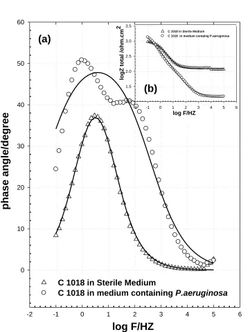
Figure 6. Bode impedance diagrams of C1018 immersed in sterile medium and medium containing P.aeruginosa; (a) Bode phase and inset (b) Impedance phase.
-2 -1 0 1 2 3 4 5 6
0 20 40 60 80
Ni-Zn-P in Sterile Medium
Ni-Zn-P in medium containing P.aeruginosa
-2 -1 0 1 2 3 4 5 6 0.5
1.0 1.5 2.0 2.5 3.0 3.5 4.0 4.5
Ni-Zn-P in sterile medium Ni-Zn-P in medium containing P.aeruginosa
log F/HZ
phas
e a
ngle/de
gree
log F/HZ
logZ
t
otal
/ohm.cm
2
(a)
(b)
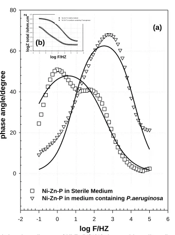
Figure 7. Bode impedance diagrams of Ni-Zn-P/C1018 immersed in sterile medium and medium containing P. aeruginosa; (a) Bode phase and inset (b) Impedance phase.
[image:12.596.120.480.79.561.2]
containing P. aeruginosa appropriate to the formation of anticorrosive biofilm thick film lying on its surface.
0 2000 4000 6000 8000 10000 12000 0
1000 2000 3000 4000
C1018 P.aeruginosa
C1018 medium
Ni-Zn-P P.aeruginosa
Ni-Zn-P medium Fitting data
Z'' real /ohm.Cm2
-Z
img
/ohm.Cm
2
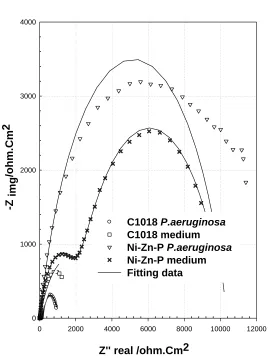
[image:13.596.165.434.121.479.2]Figure 8. Nyquist impedance diagram of C1018 and Ni-Zn-P/C1018 immersed in sterile and medium containing P. aeruginosa.
[image:13.596.129.467.541.726.2][image:14.596.73.523.251.394.2]
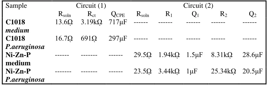
On the other hand, the spectra of C1018 for the exposure with or without bacteria can be well fitted to the circuit (1) presented in Figure 9. This result indicated that the corrosion product and non-homogenous biofilm layer is formed on C1018 in sterile media and medium containing P.aeruginosa, respectively. The calculated impedance parameters of C1018 in both media are summarized in Table 2. These values show clearly that the corrosion resistance of C1018 in sterile medium (3.16kΩ) is more than that of C1018 in medium containing P. aeruginosa (691Ω), where these values are equivalent with the inserted impedance spectra, Fig.6b.
Table 2. Values of electrochemical impedance of C1018 and Ni-Zn-P/C1018 in the sterile medium and medium containing P. aeruginosa.
Sample Circuit (1) Circuit (2)
Rsoln Rct QCPE Rsoln R1 Q1 R2 Q2
C1018
medium
13.6ῼ 3.19kῼ 717μF --- --- --- --- --- C1018
P.aeruginosa
16.7ῼ 691ῼ 297μF --- --- --- --- --- Ni-Zn-P
medium
--- --- --- 29.5ῼ 1.94kῼ 1.5μF 8.31kῼ 28.6μF Ni-Zn-P
P.aeruginosa
--- --- --- 23.5ῼ 3.44kῼ 1μF 25.34kῼ 20.5μF
The constant phase element present in the circuit (Q) is a pseudo-capacitive element which typically are related to rough surfaces [23], where
C = Q (wm) n-1 {1}
wm is the frequencyat which the imaginary part of the impedance Z” has a maximum. About the values of (QCPE) for uncoated C1018 it is observed that , the value of passive film capacitance in sterile medium has a higher value (717µF) than that in medium containing P. aeruginosa (297 µF). The increase of QCPE is dependable with a decrease in the thickness, where the inverse capacitance of the passive layer, 1/ QCPE, is straight compared to the thickness of this layer. The increase of QCPE is compatible by a decrease in the thickness of the passive layer. This important result revealed to while P. aeruginosa causes an increase in the thickness of biofilm layer formed on C1018 in medium containing bacteria, but the formed layer biofilm is not uniformly cover the surface of C1018, so it is not significantly increase its resistance in medium containing bacteria [19].
The impedance data of Ni-Zn-P coating in sterile medium or in medium containing P.aeruginosa were approved to hypothetical data according to the equivalent circuit model (2) presented in Fig. 9. In this circuit, two parallel combination terms are used, the first (Outer layer) is the charge transfer resistance, R1, and the double layer capacitance, Q1, and the second (Inner layer) is the barrier film resistance, R2, and the barrier film capacitance, Q2, both in series to the solution resistance Rs.
corrosion resistance of the duplex film is represented by the sum of the inner and outer layer resistances and also the solution resistance. The resistance of Ni-Zn-P in sterile medium (1.94 & 8.31kΩ for inner and outer layer, respectively) is lower than that the resistance of Ni-Zn-P in medium containing P. aeruginosa (3.44 & 25.34kΩ for inner and outer layer, respectively). This difference in the value of resistance be sure pointed to the thick uniform biofilm formed on Ni-Zn-P in medium containing P. aeruginosa. This revealed a positive influence of bacteria on zinc coating Ni--P alloy, which can improve the surface of C1018 in media containing bacteria [22]. This result also attributed to the present electroless method provide us alloy ternary coating with low zinc content (14.13 w%) and high nickel content (78.89 w%), this alloy is hard and has barrier resistance. Owing to the high resistance of Ni-Zn-P alloy coating, it’s not dissolve rapidly in any corrosive environment [37]. Additionally, the presence of ammonia complexing agent in electroless bath and adjust the pH of the bath at 8, both two factors help the deposition of Ni, Zn and P with a suitable weight percent as indicated in Fig.2 [37]. On the other hand, the EPS by-products of P. aeruginosa, which contain functional group, including amino acids are able to bind with the dissolved low zinc ions to form a novel uniform biofilm / Ni-Zn-P protective layer [38].
It is documented that the surface area enclosed with the biofilm is electrochemically inactive and all the current is passed via the electrode surface itself. The fraction of the surface covered with the biofilm passive layer represented by the symbole Ɵ , and (1- Ɵ) is the total fraction surface uncovered with the biofilm is given by substituted in Equation {2};
1- Ɵ = {2}, where Rt (Rt = Rpr + Rb) is the charge transfer resistance of C1018 or Ni-Zn-P alloy coating in a medium containing P.aeruginosa and Rto is the resistance of C1018 or Ni-Zn-P in sterile medium. The uncovered electrode surface by biofilm for C1018 and Ni-Zn-P alloy coating is 4.616 and 0.356, respectively.
For further investigation, the percentage inhibition efficiency (ηi) of the biofilm, which reflect the good adhesion of microbial film on Ni-Zn-P alloy surface may be confirmed by its influence on the impedance results. The Rct values were gained from the diameter of the semicircle in the Nyquist plot, and percentage inhibition efficiency (ηi) values were calculated using the following equation [39]:
η {3}
4. CONCLUSION
In this work, Ni-Zn-P alloy coating was prepared via electroless method to prevent carbon steel from biocorrosion and concluded in the following points:
1. The deposition of C1018 in NiZn electroless bath is beneficial to deposit alloy coat with high Ni content (79 wt. %) and low Zn content (14 wt. %).
2- In artificial seawater, C1018 was exposed to complete corrosion failure unlike alloy coating. 3- The Ni-Zn-P alloy coating showed the higher CFU/ml value than C1018 after 28 days of immersion in medium containing P. aeruginosa industrial bacteria, this refer to the configuration of a thick consistent biofilm layer on Ni-Zn-P alloy coating and proved by EIS results.
4- The percentage inhibition efficiency (ηi) of alloy coating in a medium containing P. aeruginosa is equal 97.599% compared to 68.87 % in sterile medium.
Therefore biofilm / Ni 78.89 Zn 14.13 P4.26 is believed to be a bi-layer alloy coating shows much better biocorrosion control in seawater than a single layer alloy coating of Ni-Zn-P and it is consider a promising coat for underground pipelines.
ACKNOWLEDGEMENT
The authors extend our thanks and appreciation to the Taif university for financial support under serial No 1-435-3419. Also, the authors advance to thank Mrs Reem Al-Santali for her participation in the experimental work.
References
1. A. Rajasekar, B. Anandkumar, S. Maruthamuthu,Y.P. Ting, P.K. Rahman, Appl. Microbiol. Biotechnol., 85 (2010) 1175.
2. Y.F. Wen, C.Z. Cai, X.H. Liu, J.F. Pei, X.J. Zhu, T.T. Xiao, Corros.Sci., 51 (2) (2009) 349.
3. A.K. Parande, S. Muralidharan, V. Saraswathy, N. Palaniswamy, Anti-Corros. MethodsMater.,
53(3) (2005) 148.
4. V. Scotto, R.D. Cintio and G. Marcenaro, Corros.Sci., 25 (1985) 18.
5. N.O. San, N. Nazır, G. Donmez, Corros.Sci., 65 (2012) 113.
6. D.J. Beale, M.S. Dunn, D. Marney, Corros.Sci., 52 (2010) 3140.
7. M. Mehanna, R. Basseguy, M.L. Delia, A. Bergel, Corros. Sci.,51 (2009) 2596.
8. B.W.A. Sherar, I.M. Power, P.G. Keech, S. Mitlin, G. Southam, D.W. Shoesmith, Corros. Sci., 53 (2011) 955.
9. N.O. San, H.Nazır , G. Donmez, Corros. Sci., 79 (2014) 177.
10. D.J. Beale, M.S. Dunn, D. Marney, Corros. Sci., 52 (2010) 3140.
11. H. Ashassi-Sorkhabi, M. Moradi-Haghighi, G. Zarrini, Mater. Sci. Eng., C 32 (2012) 303.
12. P.J. Antony, R.K. Singh Raman, R. Raman, P. Kumar, Corros. Sci., 52 (2010) 1404.
13. F. Wang, S. Arai, M. Endo, Carbon, 43 (2005) 1716.
14. S.L. Mu, N. Li, D.Y. Li, Z.L. Zou, Electrochim. Acta., 54 (2009) 6718.
15. J.T. Tian, X.Z. Liu, J.F. Wang, X. Wang, Y.S. Yin, Mater.Chem. and Phys., 124 (2010) 751.
16. K.R. Baldwin, M.J. Robinson, C.J.E. Smith, Corros. Sci., 36 (1994) 1115.
17. S. Chouchane, A. Levesque, P. Zabinski, R. Rehamnia, J.P. Chopart, J. Alloys Compd., 506 (2010) 575.
18. S.J. Yuan, A.M.F. Choong, S.O. Pehkonen, Corros. Sci., 49 (2007) 4352.
20. I.B. Beech, L. Hanjagsit, M. Kalaji, A.L. Neal, V. Zinkevich, Microbiology, 145 (1999) 1491.
21. A. Nagiub, F. Mansfeld, Corro.Sci., 43 (2001) 2001.
22. S. Pouladi, M.H. Shariat, M.E. Bahrololoom, Surf. Coat. Tech., 213 (2012) 33.
23. S.M.F. Gad El-Rab, S.A. Fadl-allah, A.A. Montaser, Appl.Surf.Sci., 261 (2012) 1.
24. J. Kreth, E. Hagerman, K. Tam, J. Merritt, D.T.W. Wong, B.M. Wu, N.V. Myung, W. Shi, F. Qi,
Biofilms, 1 (2004) 277.
25. V. Reipa, J. Almeida, K.D. Cole, J. Microbiol. Methods, 66 (2006) 449.
26. J.S.Lian, G.Y.Li,L.Y.Niu, C.D.Gu,Z.H.Jiang, and Q.Jiang, , Surf.Coat.Tech., 200 (2006) 5956.
27. B. Veeraraghavan, H. Kim, B. Popov, Electrochim.Acta., 49 (19) 15 (2004) 3143.
28. F.Garcia, A.L.R. Lopez, J.C. Guille, L.H. Sandoval, C.R. Gonzalez, V. Castano, Anti-Corros.Methods Mater., 59 (2012) 10.
29. E.J. Akpabio, E.J. Ekott, M.E. Akpan, Environ.Res., 5 (2) (2011) 59.
30. E. Juzeliunas, R. Ramanauskas, A. Lugauskas, K. Leinartas, M. Samulevicien, A. Sudavicius,
Electrochim. Acta., 51 (2006) 6085.
31. R. Zuo, E. Kus, F. Mansfeld, T.K. Wood, Corros. Sci., 47 (2005) 279.
32. J.R. Macdonald (Ed.), Impedance Spectroscopy, John Wiley & Sons, New York, NY, USA, 1987 (Chapter 4).
33. W.A. Badawy, A.M. Fathi, R.M. El-sherief, S.A. Fadl-allah, J. Alloys Compd., 475 (2009) 911.
34. S. A. Fadl-allah, Q. Mohsen, Appl. Surf. Sci. 256 (2010) 5849.
35. A.A. Oskuie, T. Shahrabi, A. Shahriari, E. Saebnoori, Corros. Sci., 61 (2012) 111.
36. C.Y. Tsai, J.S. Liu, P.L. Chen, C.S. Lin, Corros. Sci.,52 (2010) 3907.
37. B.Veeraraghavan, H.Kim, B.Popov, Electrochim. Acta., 49 (2004) 3143.
38. H.P.F. Fang, L.C. Xua, K.Y. Chan, Water Res., 36 (2002) 4709.
39. N.O. San, H. Nazır, G. Dönmez, Corros. Sci., 79 (2014) 177.