Int. J. Electrochem. Sci., 10 (2015) 5614 - 5623
International Journal of
ELECTROCHEMICAL
SCIENCE
www.electrochemsci.orgSolution Processable P3HT/CdS Hybrid Solar Cells with
Different Layer Configurations.
A. Sánchez-Martínez, Y.V. Vorobiev and R. Ramirez-Bon*
Centro de Investigación y de Estudios Avanzados del IPN. Unidad Querétaro, Apdo. Postal 1-798, 76001, Querétaro, Qro., México
*
E-mail: [email protected]
Received: 11 March 2015 / Accepted: 26 April 2015 / Published: 27 May 2015
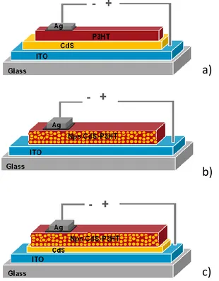
In this work we report on the assembling process of CdS/P3HT (poly(3- hexylthiophene)) hybrid solar cells on indium-tin-oxide (ITO)-coated glass substrates and their electrical output in darkness and under illumination conditions. The CdS window layers were deposited on ITO-coated glass substrates by the chemical bath method employing an ammonia-free process. The P3HT absorbing layers were deposited on the CdS/ITO/glass substrates by the casting method from solution by dissolving P3HT in chloroform. To complete the heterostructured solar cells, silver and silver-carbon (graphite) contacts on the P3HT layers were used as the back contacts. The hybrid solar cells were assembled in three different layer configurations: 1) CdS/P3HT bilayer, 2) P3HT-CdS nanoparticles (CdS NPs) hybrid composite layer and 3) CdS/P3HT-CdS NPs bilayer. The CdS NPs embedded in the P3HT matrix to obtain the composite layer were obtained from the powder precipitated during the chemical deposition of CdS films. The photovoltaic effect in the hybrid solar cells was analyzed from current density versus voltage (J-V) measurements.
Keywords: hybrid solar cells; solution growth; chemical deposition.
1. INTRODUCTION
cells the diffusion length of photogenerated carriers is very short because of the poor mobility and therefore, the conventional p-n junction has very limited efficiency for photovoltaic conversion [6-7]. This drawback of organic semiconductors has been overcome with different solar cell configurations in which the p-n interface has an increased area. The typical configuration consists of a blend of a p-type organic semiconductor as P3HT (poly(3- hexylthiophene)) and an n-type one as PCBM (Phenyl-C61-butyric acid methyl ester) [8-9]. In a proper blend, the interface area is maximized and each semiconductor must be connected to the respective contact to provide the electrical path to the photogenerated electrons and holes, after they are separated at the p-n interface. Another approach is to combine with inorganic semiconductors in organic-inorganic hybrid solar cells [10-11]. For this, the great availability of inorganic semiconductor nanostructures allows the design of different hybrid solar cell configurations. One of the simplest configurations is the system of semiconductor nanoparticles with n-type conductivity, such as CdS and CdSe, embedded in a polymeric matrix with p-type conductivity, such as P3HT [11-12].
The inorganic-organic CdS-n/P3HT-p thin film solar cell has attracted some attention because of the simplicity of depositing the absorbent P3HT layer and the excellent properties of CdS as a window layer. P3HT is a polymeric, semicrystalline, p-type semiconductor, which can be easily deposited in solution and has been used in electronic devices such as solar cells and thin film transistors [13-15]. The CdS thin films have shown to be the best window layer semiconductor material in CdS/CdTe and CdS/CIGS solar cells [16-18]. Heterostructured CdS/P3HT solar cells on ITO-coated glass substrates, with efficiency of 0.44% were reported in reference [19]. The CdS layers were deposited by the chemical bath deposition technique employing ammonia as the complexing agent, meanwhile the P3HT layers were deposited by drop casting and spin coating, and annealed at several temperatures. For the back contacts, evaporated gold on graphite electrodes were used. In reference [20], a CdS nanocrystalline layer was formed by first depositing via sputtering, a Cd layer which was then transformed to CdS by chemical reaction in a solution of sulfur-thiourea in N,N-dimethyl formamide at 120 °C for 12 hours. The P3HT layers were deposited by spin coating and the gold back contacts were deposited by thermal evaporation. The maximum efficiency attained by these hybrid solar cells was 0.068 %. In reference [21], a similar CdS nanocrystalline layer was obtained from a sputtered Cd layer by chemical reaction in a solution of sulfur powder in ethanol at 180 °C for 12 hours. The hybrid solar cell was completed with the P3HT layer deposited by spinning and the application of evaporated gold contacts. The efficiency of this solar cell was 0.03 %. The photocurrent response of the bilayer CdS/P3HT, where both layers were processed by electrodeposition, was reported in reference [22]. It was shown that the photocurrent response of the hybrid bilayer was higher than that corresponding to the organic P3HT layer.
ammonia-free CBD process for the deposition of CdS, based on the employment of sodium citrate as the complexing agent [23-25]. The process represents several important advantages such as avoiding the use of harmful ammonia as the complexing agent and the reduction of cadmium in the reaction solution, and thus also in the residues. In addition, the properties of these CdS films are good enough to be applied as window layers in CdS-CdTe and CdS-PbS thin film solar cells [26-27], and as active semiconductor layers in thin film transistors [28-30]. In this work, we assembled CdS/P3HT thin film solar cells on ITO-coated glass substrates, employing our previously reported CBD ammonia-free process for the deposition of the CdS window layers. Taking advantage of the CdS nanoparticles produced as precipitated powder during the CdS CBD process, we assembled different solar cell configurations by blending the CdS nanoparticles with the polymer semiconductor. Then, the CdS/P3HT hybrid blends were deposited by drop casting on the ITO-coated glass and CdS/ITO coated glass substrates. The output electrical responses of the hybrid solar cells in the three different configurations were analyzed from I-V measurements. From this analysis, the electrical parameters of the hybrid solar cells were determined.
2. EXPERIMENTAL DETAILS
thickness of the hybrid composite layer was 4.86 m. The back contacts in these solar cells were also graphite and silver electrodes. The scheme of the three hybrid solar cell configurations are shown in Fig. 1. The transmission (T) and reflection (R) optical spectra of the CdS and P3HT films were measured in the 240-840 nm wavelength range with a Scientific Computing International (SCI) Film TekTM 3000 spectrometer. The I-V characteristics of the hybrid solar cell structures in the darkness and under 34 mW/cm2 illumination were measured using a Semiconductor Parameter Analyzer 4155C Agilent in the voltage range from zero to 1 V in steps of 0.02 V.
Figure 1. Scheme of the three configurations of solar cells assembled and analyzed: a) bilayer P3HT/CdS, b) hybrid composite monolayer P3HT-CdSNPs and c) the bilayer CdS/P3HT-CdSNPs.
3. RESULTS AND DISCUSSION
In Fig. 2 are shown the T and R optical spectra of the CdS film deposited on ITO-coated glass substrate and of the P3HT film deposited on glass substrate. It is observed that the onset of the optical
[image:4.596.140.450.202.600.2]
absorption of the P3HT layer at about 700 nm defines a wide absorption range below this wavelength value where the optical transmission vanishes.
300 400 500 600 700 800
[image:5.596.172.424.134.383.2]0 10 20 30 40 50 60 70 80 90 100 T P3HT R P3HT R CdS T CdS T ransmi s s ion, Refl ec ti on (%) Wavelength (nm)
Figure 2. Optical transmission and reflection spectra of the CdS and P3HT films
0.1 0.2 0.3 0.4 0.5 0.6 0.7 0.8 0.9
-0.3 -0.2 -0.1 0.0 0.1 0.2 0.3 ITO CdS P3HT Glass - + Ag Ag dark Ag-C dark Ag light Ag-C light
0.0 0.1 0.2 0.3 0.4 0.5 0.6 0.7 0.8 0.9 1.0
J( m A /cm 2 ) Voltage (V)
[image:5.596.148.433.447.716.2]
This result assures the total absorption of the light in this wavelength range in the P3HT layer. On the other hand, the absorption edge of the CdS film is observed at about 500 nm. From the T spectra the values of the energy band gap for CdS and P3HT layers were determined as 2.45 and 1.94 eV, respectively.
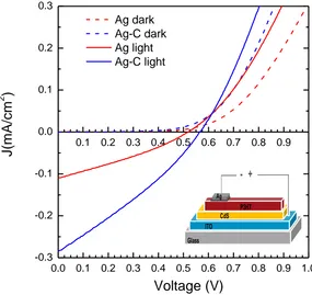
The current-density-voltage (J-V) characteristics of the P3HT/CdS/ITO/glass solar cells, measured in dark (dotted lines) and under illumination conditions (solid lines), in silver (red) and silver-graphite (blue) electrodes are shown in Fig. 3. The inset displays the scheme of the hybrid solar cell. The J-V curves measured in dark conditions show the typical exponential behaviour of a rectifying diode, evidencing the formation of the p-n junction at the interface of the CdS and P3HT layers. Under illumination, the induced photocurrent displaced the J-V curves to the negative values region of J. The Ag-C contacts produced better photoresponse of the hybrid solar cell with open circuit voltage of 568 mV and short circuit current density of 0.284 mA/cm2. The corresponding fill factor and efficiency of the hybrid bilayer solar cell were 0.30 and 0.14 %, respectively. On the other hand, the photoresponse measured with the Ag contacts produced open circuit voltage of 520 mV and short circuit current density of 0.111 mA/cm2, with corresponding fill factor and efficiency of 0.30 and 0.05 %, respectively.
0.1 0.2 0.3 0.4 0.5 0.6 0.7 0.8 0.9
-0.008 -0.006 -0.004 -0.002 0.000 0.002 0.004 0.006 0.008
ITO Glass
- +
Nps CdS-P3HT Ag
Ag dark Ag light
0.0 0.1 0.2 0.3 0.4 0.5 0.6 0.7 0.8 0.9 1.0
J(
m
A
/cm
2 )
[image:6.596.149.441.380.655.2]Voltage (V)
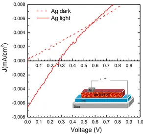
Figure 4. J versus V measurements in dark and under illumination of the composite monolayer P3HT-CdSNPs hybrid solar cell.
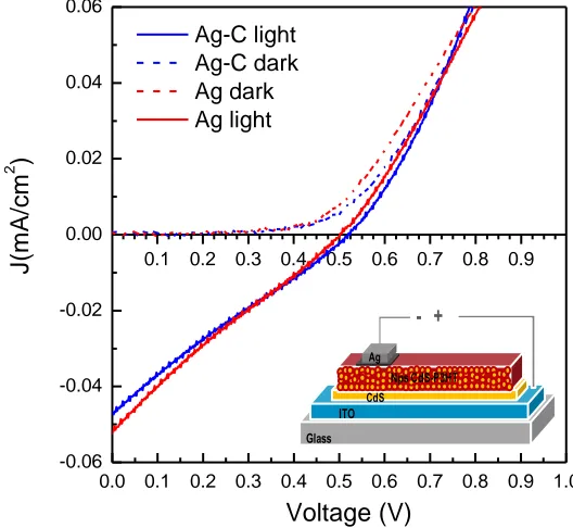
(dotted lines) and under illumination conditions (solid lines). The scheme of this hybrid solar cell is shown in the inset. In this configuration, only the silver electrodes produced acceptable photoresponse. As observed, both open circuit voltage and short circuit current density are much lower for this configuration with values of 290 mV and 0.006 mA/cm2, respectively. The corresponding fill factor and efficiency of the hybrid single composite layer solar cell were 0.23 and 0.001 %, respectively. The performance parameters of the solar cell using the composite P3HT-CdSNPs layer were improved by depositing it on the CdS window layer to attain the P3HT-CdSNPs/CdS/ITO/glass configuration. Figure 5 shows the J-V curves for this solar cell configuration measured in dark (dotted lines) and under illumination conditions (solid lines), using silver (red) and silver-graphite (blue) electrodes. The scheme of this solar cell configuration is shown in the inset. Both types of back contacts produced very similar responses either in dark or under illumination. The open voltage values increased up to 524 and 502 mV when measured with Ag-C and Ag electrodes, respectively. However, the values for the short circuit current density were low as compared with the bilayer P3HT/CdS solar cell configuration. These values were 0.047 and 0.052 mA/cm2 for the Ag-C and Ag contacts, respectively. The resultant fill factor and efficiency values were 0.24, 0.0175 % and 0.23, 0.0178 %, respectively for Ag and Ag-C contacts.
0.1 0.2 0.3 0.4 0.5 0.6 0.7 0.8 0.9
-0.06 -0.04 -0.02 0.00 0.02 0.04 0.06
ITO CdS Glass
- +
Nps CdS-P3HT Ag
Ag-C light Ag-C dark Ag dark Ag light
J(
m
A
/cm
2 )
Voltage (V)
[image:7.596.161.425.350.593.2]0.0 0.1 0.2 0.3 0.4 0.5 0.6 0.7 0.8 0.9 1.0
[image:7.596.114.488.692.751.2]Figure 5. J versus V measurements in dark and under illumination of the bilayer CdS/P3HT-CdSNPs hybrid solar cell
Table 1. Electrical parameters of the hybrid solar cells in the three analyzed layers configurations. Solar Cell Contact Jsc (mA/cm2) Voc (V) FF Ƞ(%)
CdS/P3HT Ag-C 0.284 0.568 0.30 0.14
P3HT-CdSNPs Ag 0.006 0.290 0.24 0.001
Table 1, with the parameters of the best hybrid solar cells for each configuration, summarizes the results. The hybrid bilayer P3HT/CdS/ITO/glass configuration, using silver-graphite electrodes as the back contact, produced higher short circuit current and fill factor to attain the best efficiency of 0.14 %. This solar cell efficiency is on the order of the efficiency of similar hybrid bilayer solar cells reported in the literature, where the back contacts were evaporated gold or gold on graphite electrodes [19-21]. Therefore, we attained equivalent photovoltaic efficiency in hybrid solar cells which assembly processing represents several important advantages. The hybrid solar cell was assembled employing low temperature solution deposition processes, including the process for the back contacts. The maximum temperature during the whole assembling process was 80 °C for the curing of the silver electrodes; therefore, this simple and easy assembly process would be very useful and convenient to produce flexible solar cells on plastic substrates. The ammonia-free CBD process for the CdS window layer is also advantageous because of the employment of innocuous sodium citrate as the coupling agent and the elimination of harmful ammonia in the reaction solution. Furthermore, to take even more advantage on the CdS-CBD process, the CdS powder, constituted by CdS nanoparticles, formed in the reaction solution and precipitated during the deposition process was collected and employed as active material in P3HT-NPsCdS composite layers in the others hybrid solar cells configurations. The single layer P3HT-NPsCdS hybrid solar cells showed the lowest efficiency of 0.001 %, which increased to 0.0178 % when a CdS window layer was included in the hybrid solar cell configuration. To improve the photovoltaic efficiency of these hybrid solar cells with the hybrid composite layer, it is necessary the study of the influence of the size, amount and distribution of the CdS nanoparticles in the P3HT matrix.
4. CONCLUSIONS
In this work, we have shown that organic-inorganic P3HT-CdS hybrid solar cells can be prepared in simple, low temperature, economic and more environmentally friendly solution deposition processes. Particularly, the CdS window layers were deposited by means of an environmental advantageous CBD process in which ammonia was replaced by sodium citrate as the complexing agent. The precipitated CdS powder after the CdS deposition process was collected and employed as active material in some hybrid solar cells configurations. The analysis of the bilayer P3HT/CdS hybrid solar cells characteristics shows that the photovoltaic efficiency is equivalent to that reported in the literature for other similar bilayer hybrid solar cells. The hybrid solar cells, including a P3HT-NPsCdS hybrid composite layer, showed the proper photovoltaic response, although with poorer electrical parameters than those measured in the P3HT-CdS bilayer configuration.
ACKNOWLEDGEMENTS
References
1. Youngkyoo Kim, Steffan Cook, Sachetan M. Tuladhar, Stelios A. Choulis,Jenny Nelson, James R. Durrant, Donal D. C. Bradley, Mark Giles, Iain Mcculloch, Chang-Sik Ha, Moonhor Reem. Nat. Mater. 5 (2006) 197-203.
2. Yugeng Wen, Yunqi Liu, Yunlong Guo, Gui Yu, and Wenping Hu. Chem. Rev. 111 (2011) 3358-3406.
3. T.L. Benanti, D. Venkataraman. Photosynth. Res. 87 (2006) 73-81.
4. Serap Gu¨nes, Helmut Neugebauer, Niyazi Serdar Sariciftci, Chem. Rev., 107 (2007) 1324-1338 5. Jonathan Rivnay, Rodrigo Noriega, John E. Northrup, R. Joseph Kline, Michael F. Toney, Alberto
Salleo. Phys. Rev. B 83 (2011) 121306(R).
6. N. Zhao, Y.-Y. Noh, J.-F. Chang, M. Heeney, I. McCulloch, H. Sirringhaus. Adv. Mater. 21 (2009) 3759–3763.
7. Mohammad Afzaal, Paul O’Brien. J. Mater. Chem. 16 (2006) 1597–1602.
8. Xia Fan, Mingliang Zhang, Xiaodong Wang, Fuhua Yang, Xiangmin Men. J. Mater. Chem. A,1 (2013) 8694–8709.
9. Dian Chen, Atsuhiro Nakahara, Dongguang Wei, Dennis Nordlund, Thomas P. Russell. Nano Lett. 11 (2011) 561–567.
10.Bao Sun, Yanzhong Hao, Fen Guo, Yinhu Cao, Yanhui Zhang, Yingpin Li, Dongsheng Xu. J. Phys. Chem. C 116 (2012) 1395–1400.
11.Min Zhong, Dong Yang, Jian Zhang, Jingying Shi, Xiuli Wanga, Can Li. Sol. Energ. Mat. Sol. C. 96 (2012) 160–165.
12.Smita Dayal, Matthew O. Reese, Andrew J. Ferguson, David S. Ginley, Garry Rumbles, Nikos Kopidakis. Adv. Funct. Mater. 20 (2010) 2629–2635.
13.W.H. Lee , S.Y. Chuang, H.L. Chen, W.F. Su, C.H. Lin. Thin Solid Films 518 (2010) 7450–7454. 14.L. Reséndiz , M. Estrada, A. Cerdeira, B. Iñiguez, M.J. Deen. Organic Electronics 11 (2010)
1920–1927.
15.Xiaoxia Jiang, Fei Chen, Weiming Qiu, Quanxiang Yan, Yaxiong Nan, Hao Xu, Ligong Yang, Hongzheng Chen. Sol. Energ. Mat. Sol. C. 94 (2010) 2223–2229.
16.J. Britt, C. Ferekides. Appl. Phys. Lett. 62 (1993) 2851
17.Ingrid Repins, Miguel A. Contreras, Brian Egaas, Clay De Hart, John Scharf, Craig L. Perkins, Bobby To, Rommel Noufi, Prog. Photovolt: Res. Appl. 16 (2008) 235–239.
18.A. Shah, P. Torres, R. Tscharner, N. Wyrsch, H. Keppner. Energy 285 (2000) 692–698.
19.Hugo Jorge Cortina-Marrero, Claudia Martínez-Alonso, Liliana Hechavarría-Difur, Hailin Hu. Eur. Phys. J. Appl. Phys. 63 (2013) 10201.
20.Huimin Jia, Weiwei He, Yidong Zhang, Yan Lei, Yong Xiang, Shu Zhang, Zhi Zheng. New J. Chem. 37 (2013) 3017-3023.
21.Weiwei He, Huimin Jia, Yan Lei, Adv. Mat. Res. 742 (2013) 139-142.
22.Yah Chzeh Ing, Zulkarnain Zainal, Anuar Kassim, Wan Mahmood Mat Yunus. Int. J. Electrochem. Sci. 6 (2011) 2898–2904.
23.M. B. Ortuño López, J.J. Valenzuela Jáuregui, M. Sotelo Lerma, A. Mendoza Galván, R. Ramírez Bon. Thin Solid Films 429, 34-39 (2003)
24.M. B. Ortuño López, M. Sotelo Lerma, A. Mendoza Galván, R. Ramírez Bon. Thin Solid Films 457, 278-284 (2004)
25.M. G. Sandoval Paz, M. Sotelo Lerma, A. Mendoza Galván, R. Ramírez Bon. Thin Solid Films 515, 3356-3362 (2007).
26.R. Ochoa-Landín, J. Sastre-Hernández, O. Vigil-Galán, R. Ramírez-Bon. Solar Energy 84 (2010) 208-214.
28.G. Arreola Jardón, L.A. González, L.A. García-Cerda, B. Gnade, M.A. Quevedo-López, R. Ramírez Bon. Thin Solid Films 519 (2010) 517–520.
29.A.L. Salas-Villaseñor, I. Mejía, J. Hovarth, H.N. Alshareef, D.K. Cha, R. Ramírez Bon, B.E. Gnade, M.A. Quevedo-López. Electrochem. Solid State Lett. 13 (2010) H313–H316.
30.T. Mendivil-Reynoso, L.P. Ramírez-Rodríguez, M.A. Quevedo-López, R. Ramírez-Bon, S.J. Castillo. Int. J. Electrochem. Sci. 10 (2015) 3291-3300.