Int. J. Electrochem. Sci., 8 (2013) 11492 - 11501
International Journal of
ELECTROCHEMICAL
SCIENCE
www.electrochemsci.orgElectrospun CdTe NPs Doping Poly(phenylene vinylene)
Composite Nanofibers and Their Optoelectronic Properties
Zhiyao Sun1, Yang Xie2, Cheng Wang1,3,*, Liguo Sun1, Shuhong Wang1, Liang Ni1, Pengfei Yan1,*, Yang Gao1, Linlin Zang 1, Disi Lu 1, Guoqiang Xu1
1
Key Laboratory of Functional Inorganic Material Chemistry (Heilongjiang University), Ministry of Education, 150080, P.R. China
2
Institute of Advanced Technology of Heilongjiang Academy of Science, Harbin, 150020, P.R. China 3
Key Laboratory of Polymer Functional Materials, School of Chemical Engineering and Material, Heilongjiang University, Harbin, 150080, P.R. China
*
E-mail: wangc_93@yahoo.com
Received: 22 June 2013 / Accepted: 20 July 2013 / Published: 20 August 2013
CdTe nanoparticles (NPs) with excellent fluorescence properties have been incorporated into poly(phenylene vinylene) precursor/polyvinyl alcohol (PPV/PVA) nanofibers by electrospinning. By using PVA as an intermediate, CdTe Nps were well dispersed inside the nanofibers when their content was moderate. The photoluminescence (PL) peak of the CdTe NPs in the as-prepared composite nanofibers was shifted from 577 nm to 566 nm comparing with CdTe in solution. This blue shift of the PL peak resulted from the different quantum confinement effects, which was caused by the different environment surrounding the CdTe NPs. The hybrid nanofibers were characterized morphologically and optically by scanning electron microscopy (SEM), transmission electron microscopy (TEM) and PL measurements.
Keywords: Nanofiber; Electrospinning; CdTe; PPV; Nanomaterials
1. INTRODUCTION
One-dimensional (1D) nanostructures, such as various nanorods, nanotubes, nanowires and nanofibers, have emerged as a powerful class of building blocks to construct nanoscaled photonic and electronic devices in recent years [1-2]. Electrospinning is one of the effective and versatile methods for the fabrication of 1D polymer nanofibers with diameters ranging from a few nanometers to several micrometers.
NPs have been considered as available nanostructures for the next generation devices. The incorporation of functional inorganic materials into polymer fibers is expected as smart materials because polymer nanofibers can be fabricated to multi-functional wearable devices. Many interrelated research have been investigated, such as PPV/TiO2 [4], PAN/Ag [5], PVA/SiO2 [6], PVA/Fe3O4 [7], and so on. Among the polymers, the conjugated polymers have potential applications in optical and electronic micromation because of their novel conductive and light-emitting properties [8, 9]. Combining conjugated polymer with aqueous synthetic NPs with low cost and toxicity was very attractive to prepare nanofibers.
In our investigation, we screened the precursory PPV having the advantages of water solubility and easy processability as the assembling building blocks. And we chose PVA as an intermediate, because the existence of PVA can increase the compatibility between CdTe NPs and PPV precursor, and avoided serious deposition of the NPs. By using the electrospinning method, we fabricated PPV precursor/PVA/CdTe composite nanofibers successfully. The composite nanofibers with excellent fluorescent and electricity properties are potentially interesting for many applications such as micro- and nano- optoelectronic devices and systems.
2. EXPERIMENTAL
2.1 Materials
Tetrahydrothiophene and p-xylylene dichloride were purchased from Tokyo Chemical Industry Co. Ltd. PVA(Dp=1750) was purchased from Acros Co. Ltd. Sodium borohydride (NaBH4), tellurium (Te) powder, cadmium chloride (CdCl2·2.5H2O) and thioglycolic acid (TGA) were all obtained from Sinopharm Chemical Reagent Co. Ltd. All the chemicals were used without further purification.
2.2 Synthesis of Thiol-stabilized CdTe NPs
Thiol-stabilized CdTe NPs were synthesized according to Ref. 10. In brief, 1.8 g NaBH4 was mixed with 2.5 g Te powder in a 50 mL flask deaerated with N2 in advance. Then 30 mL of deionized water was added into the system. The reacting system was kept in ice for about 10 h. As a result, NaHTe was obtained in clear supernatant.
2.3 Preparation of PPV Precursor
The PPV precursor was prepared according to Wessling’s synthetic route [11] and the optimized conditions provided by Halliday and co-workers [12]. PPV precursor aqueous solution was dialyzed in water for a week, and then it was placed in a ventilated place for a week to remove the water fully. As a result, the thick solution of PPV precursor was obtained.
2.4 Preparation of Electrospinning Solutions
0.2 g PVA was dissolved in 1.8 g water to form 10% PVA solution. Then a determined amount of PPV precursor solution (the concentration of the solution was about 3 wt %) was added to the PVA solution. The mixture was stirred for 10 min, and then CdTe NPs were added into the mixture. After stirring for a while, the solution became homogenous and it was ultrasonically treated for 10 min before electrospinning. The content of CdTe NPs was 4 wt% in PVA, and 2 wt%, 3 wt%, 4 wt% and 6 wt% in PPV precursor/PVA solution, respectively. The concentration of PPV precursor in all the samples was 0.5 wt%.
2.5 Preparation of Electrospinning Nanofibers
The electrospinning setup used in this study consisted of a 10 mL syringe with a needle (IDZ 0.8 mm), an aluminum collecting plate and a high voltage supply. The PPV/PVA/CdTe spinning solutions were electrospun at a positive voltage of 20 kV and a working distance of 20 cm (the distance between the needle tip and the take-over).
2.6 Characterization
The morphology of the resulting composite nanofibers was studied by field-emission scanning electron microscopy (FE-SEM, MX2600FE) and transmission electron microscope (TEM, FEI TECNAI F20). FT-IR spectra were recorded from a KBr window on a Nicolet Avatar 360 FT-IR spectrophotometer. A combined stead state fluorescence and phosphorescence lifetime spectrometer (FLSP920) was used to obtain the PL spectra of the as-spun nanofibers and the excitation wavelength was 470 nm. The fluorescent images of the nanofibers were taken from a fluorescence microscopy (TE2000-U). X-ray diffraction (XRD) (D8 advance) studies were performed to investigate the crystallization of CdTe NPs.
3. RESULTS AND DISCUSSION
3.1 CdTe NPs Analysis
good dispersed crystalline structure and the shape of the as-prepared NPs was irregular. The fringe spacing of 0.22 nm corresponded to the (220) cubical zinc blende interplanar [13].
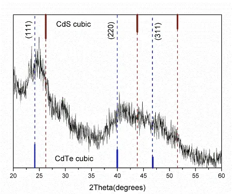
[image:4.596.126.469.215.398.2]Figure 2 showed the XRD patterns of CdTe nanocrystalline. Broad peaks typically due to the small particle size were observed, which was well in agreement with Ref. 14. The diffraction peaks of CdTe NPs can be assigned to the diffraction planes of the cubic zinc blend structure of bulk CdTe crystal. In addition, it was also clearly observed that the diffraction peaks of CdTe exhibited slight movement compared with the standard diffraction index.
Figure 1. TEM image of CdTe NPs.
[image:4.596.178.417.545.745.2]This may be due to the fact that the synthesized CdTe NPs were thiol-stabilized under the pH value of 11. Under this situation, thiol may coordinate with Cd2+, and Cd-S-R complexes analogous to a shell around were formed. The existence of organics may impact the crystallization of CdTe NPs appreciably.
[image:5.596.169.428.137.356.2]
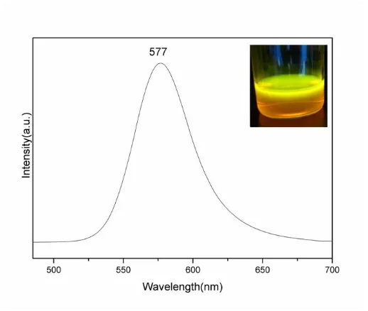
Figure 3 was the fluorescence spectrum of CdTe aqueous solution. It was clearly seen that CdTe had a main emission peak at 577 nm, which was consistent with the bright orange observed from the photo (insert of Figure 3).
Figure 3. Fluorescence spectrum of CdTe aqueous solution (insert part is the photo of CdTe under the illumination of UV-light).
[image:5.596.113.486.664.768.2]3.2 PPV/PVA/CdTe Composite Nanofibers Analysis 3.2.1 Morphology Analysis
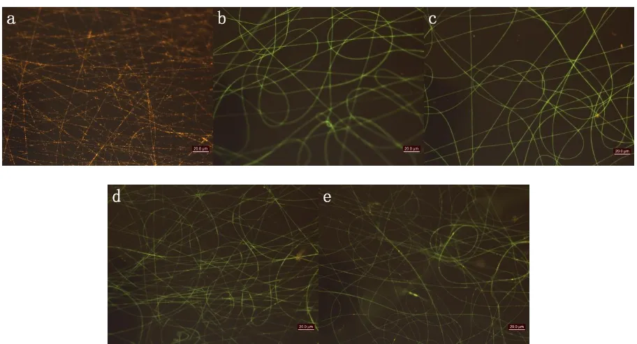
Figure 4. SEM images of the nanofibers: (a) PVA, (b) PVA/CdTe(4 wt%), (c) PPV precursor/PVA/CdTe (2 wt%), (d) PPV precursor/PVA/CdTe(3 wt%), (e) PPV precursor/PVA/CdTe(4 wt%) and (f) PPV precursor/PVA/CdTe(6 wt%).
The internal morphology and the CdTe NPs dispersion of the composites were investigated by TEM, presented in Figure 5. It can be clearly seen that the CdTe NPs were basically uniformly dispersed in the PVA nanofibers and their average diameter was only a few nanometers (Figure 5a). Owing to the exchange of the electric charges, the dispersion of CdTe NPs was somewhat affected when PPV precursor was inducing into the nanofibers. Some of the NPs began to aggregate with the increase of the content of CdTe. When the content of CdTe NPs reached to 6 wt%, the NPs formed large aggregation. Consequently, the existence of PVA weakened the interaction between the NPs and the PPV precursor, and the NPs were basically uniformly dispersed in the composite nanofibers when their concentration was moderate.
[image:6.596.109.489.70.172.2] [image:6.596.115.483.429.704.2]
3.2.2 FT-IR Spectra Analysis.
[image:7.596.181.413.107.290.2]
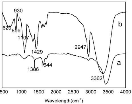
Figure 6. FT-IR spectra of the nanofibers: (a) PVA/CdTe and (b) PPV precursor/PVA/CdTe.
Figure 6 presented the FT-IR spectra of the nanofibers in the wavenumber ranging from 500 to 4000 cm-1. For the PVA/CdTe nanofibers, the absorption peaks at 1386 cm-1 and 1644 cm-1 were due to C=C stretching vibration; the absorption peak at 2947 cm-1 was assigned to C-H stretching vibration. Additionally, it can be found that the characteristic peak of O-H group at 3362 cm-1 appeared in the spectrum, which was regarded as the associated hydrogen bonds among the molecules. Different from Figure 6a, there were some obvious absorption peaks belonging to PPV precursor in Figure 6b. The peaks at 620 cm-1, 852 cm-1 and 930 cm-1 were due to C-S stretching vibration, C-H plane bending vibration of p-substituted of benzene ring and C-H out-of-plane vibration of trans-ethylene respectively. It was implied that the backbone structure of PPV precursor was not damaged when mixing with PVA and CdTe. However, the peak at 1107 cm-1 seen from Figure 6b belonged to C–O–C asymmetric stretching mode, which revealed that the PPV precursor preferred to react with PVA to form C–O–C linkages.
3.2.3 Fluorescence Spectra Analysis.
electric field also accelerated the evaporation of solvent, which has been reported in the literature [17]. The difference in the quantum confinement effects depended on the microstructure wrapping around CdTe NPs-related PL peak. Namely, in the case of pure CdTe NPs solution, the CdTe NPs were surrounded by water, whereas in the CdTe composite nanofibers, the CdTe NPs were surrounded by PVA and PPV precursor molecules.
In Figure 7, the inset was the PL spectrum of PPV precursor nanofibers. It was clearly seen that the main emission was at 521 nm, which presented obvious blue shift compared with that of pure PPV(554 nm) [4]. Figure 7b-e gave the PL spectra of the PPV precursor/PVA/CdTe composite nanofibers. It can be found that a new emission at 513 nm appeared when PPV precursor existed in the composite nanofibers, which exhibited slight blue shift compared with that of PPV precursor nanofibers (521 nm). This phenomenon can be explained by two reasons: First, the PPV precursor was not further heated over 220 ℃; Second, part of the PPV precursor chain reacted with PVA to form C-O-C linkages, which interrupted the conjugation of PPV polymer chains and decreased the p-conjugated chain length [18]. When the CdTe NPs concentration increased from 2 wt% to 6 wt%, the emission peak of the CdTe NPs near 560 nm shifted from 554 nm to 561 nm as a result of light re-adsorption and/or slight Fluorescence Resonance Energy Transfer (FRET) [19]. Besides, the PL intensity of CdTe NPs was enhanced with the increase of CdTe concentration. The PL results indicated that the NPs dispersed well in the resulting nanofibers and the process of electrospinning prevented the further occurrence of FRET.
Figure 7. Fluorescence spectra of the composite nanofibers: (a) PVA/CdTe(4 wt%), (b) PPV precursor/ PVA/CdTe(2 wt%), (c) PPV precursor/PVA/CdTe(3 wt%), (d) PPV precursor/PVA/CdTe(4 wt%) and (e) PPV precursor/PVA/CdTe(6 wt%). Inset is the fluorescence spectrum of PPV precursor nanofibers.
3.2.4 Fluorescence Photos Analysis.
[image:8.596.178.417.419.607.2]
accordance with the results of the SEM images. PVA matrix was non-luminous and pellucid, thus the orange CdTe NPs inside the nanofibers can be clearly seen. And the NPs were well dispersed in the composite fibers. When introducing PPV precursor, the color of the nanofibers turned from orange to yellow-green which originated from the PPV structure. Although the content of PPV precursor was low, the fluorescence intensity was still strong. When the content of CdTe NPs was less than 4 wt%, the NPs were hardly seen from the photos. In Figure 8d and 8e, some aggregated particles can be observed clearly, and the fluorescence color of nanofibers had slightly changed.
Figure 8. The fluorescence photos of composite nanofibers: (a) PVA/CdTe(4 wt%), (b) PPV precursor/PVA/CdTe(2 wt%), (c) PPV precursor/PVA/CdTe(3 wt%), (d) PPV precursor/ PVA/CdTe(4 wt%) and (e) PPV precursor/PVA/CdTe(6 wt%).
4. CONCLUSIONS
[image:9.596.70.526.212.458.2]
ACKNOWLEDGMENT
The present study has been supported by NSFC (51273056, 21202091, 21074031 and 51310105037), CPDF (201104456), NSF of Heilongjiang (E201118 and E201144), Abroad Person with Ability Foundation of Heilongjiang Province (2010Td03 and 12521400) and Innovation Fellowship Foundation of Heilongjiang University (Hdtd2010-11).
References
1. N.K. Hassan, M.R. Hashim, Y. Al-Douri and K. Al-Heuseen, Int. J. Electrochem. Sci., 7 (2012) 4625.
2. Y. Xia, P. Yang, Y. Sun, Y. Wu, B. Mayers, B. Gates, Y. Yin, F. Kim and H. Yan, Adv. Mater., 15 (2003) 353.
3. J. Bouclé, P. Ravirajan and J. Nelson, J. Mater. Chem., 17 (2007) 3141.
4. C. Wang, E.Y. Yan, Z.H. Huang, Q. Zhao and Y. Xin, Macromol. Rapid Commun., 28 (2007) 205. 5. Q.B. Yang, D.M. Li, Y.L. Hong, Z.Y. Li, C. Wang, S.L. Qiu and Y. Wei, Synthetic Met., 137
(2003) 973.
6. M Krissanasaeranee, T. Vongsetskul, R. Rangkupan, P. Supaphol and S. Wongkasemjit, J. Am. Ceram. Soc., 91 (2008) 2830.
7. S.H. Wang; C. Wang, B. Zhang, Z.Y. Sun, Z.Y. Li, X.K. Jiang and X.D. Bai, Mater. Lett., 64 (2010) 9.
8. Z. Wen, E. Yan and Z. Huang, Curr. Appl. Phys., 9 (2009) 189.
9. N. Hamizi, C. Ying and M. Johan, Int. J. Electrochem. Sci., 7 (2012) 4727. 10. H. Zhang, Z. Zhou, B. Yang and M.Y. Gao, J. Phys. Chem. B, 107 (2003) 8. 11. R.A. Wessling, J. Polym. Sci: Polym. Symp., 72 (1985) 55.
12. D.A.D. Halliday, P.L. Burn, R.H. Friend, D.D.C. Bradley and A.B. Holme, Synthetic Met., 55 (1993) 902.
13. C. Wu, L. Shi, Q. Li, H. Jiang, M. Selke, L. Ba and X. Wang, Chem. Res. Toxicol., 23 (2010) 82. 14. H. Zhang, Z. Zhou and B.J. Yang, J. Phys. Chem. B, 107 (2003) 8.
15. N. Bhardwaj and S.C. Kundu, Biotechnol. Adv., 28 (2010) 325.
16. R. Fernández, P. Ferreira-Aparicio and L. Daza, J. Power. Sources., 151 (2005) 18. 17. F.C. Lai, M. Huang and D.S. Wong, Drying Technol., 22 (2004) 597.
18. W. Zhang, Z.H. Huang, E.Y. Yan, C. Wang, Y. Xin, Q. Zhao and Y.B. Tong, Mater. Sci. Eng. A, 443 (2007) 292.
19. M.J. Li, J.H. Zhang, H. Zhang, Y.F. Liu, C.L. Wang, X. Xu, Y. Tang and B. Yang, Adv. Funct. Mater., 17 (2007) 3650.