C o p in g w ith D e m o n s tra tio n
S u b o p tim a lity in R o b o t P ro g ra m m in g by
D e m o n s tra tio n
J a s o n R o b e r t C h e n
B.E. (Hons), University of SydneyJuly 2001
A thesis submitted for the degree of Doctor of Philosophy
of The Australian National University
Department of Engineering
D e c la ra tio n
The work contained in this thesis, except where explicitly stated, is original research,
the major portion of which has been conducted by the author. He worked under the
supervision of the members of the advisory panel, namely Professor Alex Zelinsky, Dr.
Brenan McCarragher Dr. Matt James, and Dr. Henry Gardner. This work has not been
submitted for a degree at any other university or institution.
Much of the research contained in this thesis has been published in book chapters and
conferences, as listed below.
B o o k C h a p te r s
[Bl] J. R. Chen and B. J. McCarragher, “Configuration Space Generation for Assem
bly Tasks from Demonstration”, In J.Billingsley, editor, Mechatronics and Machine
Vision, pages 349-364, Research Studies Press Ltd., 2000
C o n fe r e n c e P a p e r s
[C5] J. Chen and A. Zelinsky, “Programming by Demonstration: Removing Suboptimal
Actions in a Partially Known Configuration Space” , Proceedings of the 2001 IEEE
Conference on Robotics and Automation, Seoul, 21-26 May 2000.
[C4] J. Chen and A. Zelinsky, “Generating a Configuration Space Representation for
DECLARATION
Robotics and Automation, Seoul, 21-26 May 2000.
[C3] J. Chen and B.J. McCarragher, “Programming by Demonstration - Constructing
Task Level Plans in a Hybrid Dynamic Framework” , Proceedings of the 2000 IEEE
Conference on Robotics and Automation, pp. 1402-1407, San Francisco, 24-28 April
2000.
[C2] J. Chen and B.J. McCarragher, “Programming by Demonstration using Hybrid Dy
namic System Modeling”, Proceedings of the Australian Conference on Robotics and
Automation, pp. 138-143, Brisbane, 30 March - 1 April 1999.
[Cl] J. Chen and B.J. McCarragher, “Programming by Demonstration - Building Event
Paths in a Hybrid Dynamic Framework”, Proceedings of the 1998 IEEE Conference
on Robotics and Automation, pp. 518-523, Leuven, 16-20 May 1998.
Department of Engineering,
Faculty of Engineering and Information Technology,
The Australian National University,
Canberra, ACT 0200, Australia.
A ck n o w led g em en ts
First and foremost, thank you to my supervisors Prof.Alex Zelinsky, Dr.Brenan McCar-
ragher, and Dr.Matt James, who all provided valuable feedback and support at different
stages of the PhD. Thank you also to others at the ANU who made life easier and/or
more enjoyable: to Peter Aigner and David Austin for showing me in the early days how
the system worked, to Tomasz Celinski for the many interesting discussions we had on
topics I cannot even begin to recall, to James Macnicol for your assistance in the vagaries
of the Sun operating system, to Bruce Mascord for prompt production of experimental
apparatus, and to Sue Cameron and Josephine Farmer for your help with the wealth of
administrative matters that arose during the course of my degree. In my personal life,
thank you to my wife Ingrid. It was you who provided support when the pressures of
the degree become great. Thank you also to my Family, who sustained infrequent visits
because of my commitment to this degree.
J.R.C.
A b s tr a c t
Finding a simple but powerful robot programming method for realistic tasks has been
one of the main aims of robotics researchers for over two decades. A promising approach
is robot Programming by Demonstration (PbD). Here, a demonstration of the task is
interpreted by a PbD interface so that a set of control commands to achieve the task are
produced for the robot. PbD is a promising approach to robot programming, however
a well known weakness of the method is that human demonstrations can be suboptimal.
Research has identified that demonstrations can contain inconsistencies, noise, or even
incorrect or unintended actions. In this thesis our focus is on identifying and removing
sub-optimality from the demonstration. Our aim is to ensure that control commands
formed for the robot from demonstrated actions encode efficient and reliable execution
of the task. The work we propose is divided into three distinct areas. They are: (i)
determining task-specific, geometric properties of a task from demonstration, (ii) deriving
efficient, low-level, robot control-commands from demonstration, and (iii) determining
optimal task-level strategies from demonstration.
Research area (i) is important since knowledge of task geometry can help identify
the presence of suboptimal actions in the demonstration. Our solution uses the concept of
Configuration Space (C-space) as a means to represent task geometry. We apply statistical
regression analysis to build-up a knowledge of task geometry in regions of the task that were
visited in the demonstration. Experimental results showed the validity of the approach.
ABSTRACT
determined. That is, a representation of C-space was determined only for regions of the
task visited in the demonstration. Second, the method could determine quite accurately
the true geometric properties of the task, so long as it had sufficient information to do so.
That is, C-space was derived accurately in regions visited often in the demonstration, and
less accurately in less-visited regions.
Research area (ii) involves deriving low-level control commands for the robot from
demonstration, and has been the main focus of research into removing demonstration
sub-optimality in PbD to date. In this thesis we adopt the well known control regime
of hybrid force-position control, and so the problem divides into two sub-areas: position
control-command synthesis, and force control-command synthesis. For position control-
command synthesis we present a novel method for path planning in a partially known
C-space. The method has the advantages compared to other methods in the literature
that, it can derive paths containing undemonstrated points, it is applicable to a task
with any degree of freedom, and that it does not assume a set form of demonstration
topology. A drawback of the approach is that, theoretically, in some circumstances a valid
control command will not be derived. However, we show with experimental results for a
realistic task how with appropriate tuning, the method will produce a valid set of position
control commands. For force control-command synthesis, a well known characteristic of
force commands recorded from a demonstration are that: they include friction, and that
force sensors introduce into these forces a high frequence noise component. We use our
knowledge of C-space to determine an appropriate direction for force control. We base
the magnitude of force control commands on the forces commanded by the human in
the demonstration, however we remove friction and noise using filtering and spline fitting
techniques.
Research area (iii) has to our knowledge not been the subject of work in the PbD field
to date. In this thesis, we identify that a set of demonstrations will contain many different
task-level strategies. Some of these will result in more optimal robot performance of the
ABSTRACT
It is based on the concept of modeling skill in a task as a Hybrid Dynamic System. The
Hybrid Dynamic System representation allows a demonstration to be represented at a
task level as a sequence of discrete events. Our method is to form an automaton from the
event sequences encoded by each demonstration. We use a set of metrics to determine a
cost for each event in the automaton. Finally, an optimal task level strategy is produced
by conducting a least cost path search in the automaton. We show with experiments how
the task-level strategies selected by our method do in fact result in more optimal robot
C o n te n ts
D ecla r a tio n i
A ck n o w le d g e m en ts iii
A b stra c t iv
Table o f C o n te n ts vii
List o f F ig u res xi
List o f T ab les xiii
N o m e n c la tu r e x iv
1 In tr o d u c tio n 1
1.1 In tro d u ctio n ... 1
1.2 General Approaches to Robot Program m ing... 5
1.2.1 Robot Programming Languages... 5
1.2.2 Modular Code Libraries and T o o l-se ts ... 7
1.2.3 Simulation and Graphical User I n te rf a c e s ... 9
1.2.4 Natural Language ... 11
1.2.5 Virtual R e a lity ... 13
1.3 Robot Programming by Demonstration ... 15
CONTENTS
1.3.2 Literature Review ... 16
1.3.3 Making PhD Robust to N o ise ... 22
1.4 C o n trib u tio n s... 25
1.5 Outline of the T h e sis... 26
2 P r o g r a m m in g b y D e m o n s tr a tio n for a S p in d le -A s s e m b ly T a sk 28 2.1 Introduction... 28
2.2 The Spindle-Assembly T a s k ... 29
2.3 Hybrid Dynamic System Modeling of Assembly S k i l l ... 31
2.4 The Configuration Space Representation for A ssem b ly ... 39
2.5 Demonstrating the Spindle-Assembly T a s k ... 41
2.6 Conclusion ...47
3 C o n fig u r a tio n S p a c e D e r iv a tio n fro m D e m o n s tr a t io n 48 3.1 Introduction... 48
3.2 Problem Form ulation... 49
3.3 Process Monitor A ssum ptions... 50
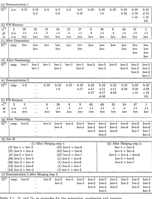
3.4 Finding a Constraint Set for each Demonstrated S t a t e ...52
3.4.1 G e n e ra tio n ... 54
3.4.2 N u m b e rin g ... 55
3.4.3 M erg in g ... 58
3.4.4 Results ... 60
3.5 Deriving Equations for Primitive C -surfaces... 63
3.5.1 The Regression Model and Data S e t ... 64
3.5.2 Regression A n a ly s is ... 68
3.5.3 Results ... 69
CONTENTS
4 L ow -level C ontrol C om m and S y n th esis from D e m o n str a tio n 75
4.1 Introduction... 75
4.2 Problem Form ulation... 76
4.3 Position Control-Command Synthesis ... 78
4.3.1 Problem Formulation ... 78
4.3.2 O v e rv ie w ... 81
4.3.3 Creating Boundary S e g m e n ts... 83
4.3.4 Growing Likely Free R e g io n s ... 86
4.3.5 Creating Interior S e g m e n ts ... 91
4.3.6 Creating a Connectivity G r a p h ... 93
4.3.7 Setting Parameters to Appropriate V alu es... 97
4.3.8 Results ...99
4.4 Force Control-Command S y n th e sis... 107
4.4.1 Force Command Synthesis based on Demonstrated Force ... 109
4.4.2 Force Command Synthesis without Demonstrated F o r c e ... I l l 4.4.3 Results ...114
4.5 Conclusion ... 116
5 S electin g O p tim al T ask-L evel S tra teg ies from D e m o n str a tio n 118 5.1 Introduction... 118
5.2 Problem Form ulation...119
5.3 Selecting a Desired Event P a t h ... 122
5.3.1 Defining Optimal Robot P e rfo rm a n c e ...123
5.3.2 The Path Selection F ram ew o rk ... 124
5.4 R esults... 130
5.4.1 Paths Selected by Fram ew ork... 130
5.4.2 Robot Execution of Selected P a t h s ...134
CONTENTS
6 C onclu sion s 142
6.1 Introduction...142
6.2 Major Results and C onclusions... 142
6.3 Further R ese arch ...144
6.3.1 Regression analysis using force d a t a ... 144
6.3.2 Process monitor a ssu m p tio n s... 145
6.3.3 Optimising paths across s t a t e s ... 145
6.3.4 Setting parameters for position control command s y n th e s is ... 146
6.3.5 Discrete event sequence as task-level d e s c r ip tio n ... 146
L ist o f F igu res
1.1 Schematic representation of the PbD robot programming m e th o d ... 3
2.1 The spindle-assembly task chosen for P b D ... 29
2.2 Discrete states defined on the basis of motion constraints applied by the
supports on the s p i n d l e ... 33
2.3 The Hybrid Dynamic System skill model for assembly t a s k s ...34
2.4 Part of the automaton of discrete states for the spindle-assembly task . . . 37
2.5 Apparatus used to capture human’s demonstration of the spindle assembly
t a s k ... 42
2.6 The set of state sequences demonstrated by the human in the
spindle-assembly t a s k ...45
2.7 The discrete state automaton Ad, constructed as that part of A visited in
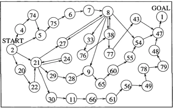
the demonstration set D\ to Dq... 46 3.1 Results of the generation, numbering and merging phases applied to demon
stration set D\ to Dq... 61 3.2 Regression model derivation for constraints caused by spindle body contact
with the right s u p p o r t ... 66
3.3 Regression model derivation for constraints caused by spindle head contact
L I ST OF FIGURES
4.1 An example of Ccon used to present five requirements on our method for
position control command synthesis... 79
4.2 Demonstration segments identify regions on a C-surface that are likely to
be obstacle f r e e ... 83
4.3 Four examples of boundary segments for state 8, (a) in state 7, (b) in state
38, (c) in state 9, and (d) in state 5 4 ...85
4.4 Example of how demonstrated points determine a set of valid bounded
sub-regions ...87
4.5 Spindle configurations generated for a number of likely free regions in state
8. Figures (a), (b), (c) and (d) correspond to likely free regions generated
from boundary segments in state 7, 38, 9, and 54 resp ectiv ely ...90
4.6 Three interior segments determined for state 8. The interior segments were
derived from paths demonstrated in state 8, ie. from demonstration 4 (7-8-
27) in (a), from demonstration 2 (27-8-38) in (b), and from demonstration
1 (38-8-54) in ( c ) ... 92
4.7 Example of points generated by our method for a simple, planar C-surface . 94
4.8 An example of the process showing (a) an original demonstrated path con
taining noise, and (b) the noise-free path that re s u lte d ... 104
4.9 An undemonstrated P(t) derived to traverse in state 8 between states 7 and
54 ... 106
4.10 An example of how P (i) can be divided into segments of distinct types . . . 108
4.11 Force signals produced by each step of the F(t) derivation process for P(t)
number 2 0 ... 113
5.1 Event paths selected by our fram ework... 131
L ist o f T ables
3.1 D\ and D2 as examples for the generation, numbering and merging phases . 56
3.2 The set of distinct constraints existing in the demonstration s e t ... 62
3.3 Results of regression analysis for the spindle-assembly ta s k ... 70
4.1 Results of our P(t) derivation method for the set of P (t) required for ex
periments in Chapter 5 ... 100
5.1 The task-level execution strategies demonstrated for the spindle-assembly
t a s k ...120
N o m e n c la tu re
Acronyms and Abbreviations
CC C-space C-surface DEC EPP HDS PM RMSE SSE
Continuous Controller Configuration Space Configuration Surface Discrete Event Controller Event Path Planner Hybrid Dynamic System Process Monitor
Root Mean Squared Error Sum Squared Error
Symbols
A
Ad
A*
{6, c, d, e, / } {6, c, d, e, /}
cf
4
c* CA ct C con C f r e eC o b s
C tk C rk Cek C n k
automaton of discrete states in the task
automaton of states in the task visited in the demonstration automaton of contact defining states visited in the demonstration set of true parameter values for scalar equations <f>i and fa
set of estimate parameter values for scalar equations </q and (f)2
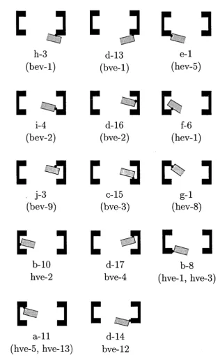
C-surface for the ith distinct state in the task primitive C-surface defined by constraint
pf-surface in C-space defined by p*m
C-surface for the wthstate in desired state path A PM information primitive describing constraint type contact defining part of C-space
obstacle-free part of C-space non-obstacle-free part of C-space
cost of event in the time performance area cost of event in the reliability performance area cost of event in the control effort performance area
NOMENCLATURE Ck D Dp dst eps V fp
fp w
prjf f 1 *0 fl xn,+1 fV Jo f l
J T ll + l
T p
F (t) gi 9s k
c
mcd_d mcd J md n Pn,+1 P (t)Q R
S
s
u (t)) Wt
wr
We
overall cost assigned in Ad for event
the demonstration set
the pth demonstration in the demonstration set
distance from boundary segment at which point Q will be generated minimum distance from boundary segment at which a point Q can be generated
graph describing connectivity between points on a C-surface in interior segments
force control vector in F(t)
demonstrated force vector at point p
projection of fp onto the force control space T v
force command derived for point force command derived for point p^ magnitude of force vector
magnitude of force vector f^/+1
force control subspace at point p on a C-surface
force control component of Hybrid Controller Command PM information primitive describing constraint gain or loss equation describing the sth constraint in the task
graph describing connectivity between all generated points on a C-surface graph describing connectivity between points on a C-surface in likely-free regions
maximum connected distance between two points in a distinct interior segments
maximum connected distance between two points in likely-free-regions maximum distance from boundary segment at which a point Q can be generated
dimension of C-space
position control vector in P (t)
time derivative of P(t) at p
start point in the P(£) derived for state 7^ end point in the P (t) derived for state 7^,
generic undemonstrated point in a segment 7 of P (t)
demonstrated point in P(t) prior to segment 77 demonstrated point in P(t) following segment 77
position control component of Hybrid Controller Command generic point in likely free region
generic point in boundary segment basis of force control subspace T p
orthonormal basis of force control subspace T v
control input vector in the continuous-time system weighting value in the time performance area weighting value in the reliability performance area weighting value in the control-effort performance area
NOMENCLATURE
xM
[y , 5]T
tpA
A3 i t It Dp lr 7a Iw V X Pij pf,~ D p Prs
*
Pm
Tk
T a1 w
t i t
Citp
Q.xa LW
state vector in the continuous-time system configuration vector in spindle-assembly task
generic scalar equations for the in the spindle assembly task equation for the j th primitive C-surface defining c f
ith possible discrete state in the task
rth discrete state visited in an assembly sequence the r th discrete state in the demonstrated sequence Dp wth distinct discrete state in state sequence A
generic sequence of points on a C-surface desired state path
the j th constraint existing in the true constraint set Llf
the j th constraint existing in the constraint set estimate t i t
the sth constraint existing in the constraint set estimate f l f P
the m th constraint in Ll* kth possible event in the task
wtfl distinct event in event sequence a
the set of motion constraints existing in itfl distinct state in the task
estimate of the set of motion constraints existing in ith distinct state in the task
estimate of the constraint set for the r th state in the Dp
the set of unique constraints existing in D
C hapter 1
I n t r o d u c t i o n
1.1
In tr o d u c tio n
Early visions of robots were of household helpers: robots to clean the house, help with
the shopping, or to wash the car. In reality, today almost all robots exist in factory
environments [53]. Recently there has been a resurgence of interest in expanding robotic
application out of the factory and into domestic type environments; so called service
robotics [8]. Recent publications show robotic research in areas such as health care [83],
recreation/entertainment [71], domestic transport [18], education [70], construction [100]
and the home [50]. Robotics research in these areas is certainly a worthwhile exercise.
Schraft [94], for example, predicts enormous economic, scientific, and social payoffs if the
transition of robots out of the factory and into service environments can be successfully
made.
A major difference between service environments and the more traditional, industrial
domain of robotics, is that robots must be able to interact with non-technical users. Such
users will in general be unfamiliar with computer technology, and will almost certainly
have no experience in robotics. Then an important question is one of how should users
communicate with robots in these domains? More specifically, how should these users
CHAPTER 1. INTRODUCTION
Current methods of programming used in industry are not suitable for service environ
ments. The two main methods of robot programming in the factory today are (i) writing
code by hand, and (ii) teach pendant methods; where the robot is lead through a series
of points that are recorded and played back directly at run-time. These programming
methods are clearly not suitable for use in service environments. First, writing code is
a skill not possessed by many end users in typical service environments. Second, it is
well known that teach pendant methods, while natural for the programmer, are limited
to programming non-contact type tasks [2]. Clearly, a new approach to robot program
ming for service environments is needed. We see three required characteristics for robot
programming systems operating in service environments. They are:
1. The system requires a non-technical user interface, preferably one that is natural
and intuitive for humans. By non-technical, we mean that it is usable by end-users
not familiar with either robotics or computer-science techniques and terminologies.
2. It can program the robot to complete typical everyday service-robotic-type tasks, ie.
it copes with tasks involving contact and constrained motions between task objects.
3. It has a-priori information requirements about the task to be programmed that are
realistic for a service-robotic type environment. For example, unlike in the factory,
a full geometric model of the task (eg. a CAD model) is unlikely to be available.
A promising approach to robot programming that fulfills these three requirements is
Programming by Demonstration (PbD). Here, robot programming is based on a demon
stration of the task provided by the end user. The end user provides a demonstration of
the task, and a PbD interface lying between the robot and demonstrator interprets the
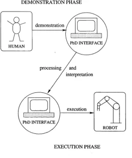
demonstration and determines the control details required by the robot . Two phases to
PbD exist. The first is the demonstration phase, where the information about how to
execute the task is extracted from the demonstration. The second phase is the execution
phase, where the PbD interface controls the robot to achieve the task. We show in Figure
CHAPTER 1. INTRODUCTION
DEMONSTRATION PHASE
dem onstration
PbD INTERFACE HUMAN
p ro cessin g / and
interpretation
ex ecu tio n
PbD INTERFACE
ROBOT
EXECUTION PHASE
Figure 1.1: Schematic representation of the PbD robot programming method
PbD is a method that promises to fulfill our three requirements for the following
reasons. First, it provides a very natural and intuitive programming method for humans.
For example, work by Patrick [58] showed that in human-to-human interaction, instruction
by demonstration and practice is the preferred mode of skill transfer. Second, PbD can be
used to program a wide range tasks. Its only limitation is that the human can complete the
task himself. The strength of PbD in this respect is reflected by the diverse range of tasks
presented for PbD in the literature, eg. door-opening [63], metal grinding [117], peg-in
hole assembly [63, 90], balancing an inverted pendulum [7], sandwich making [123], driving
an automobile [20], etc. Third and finally, limited a-priori information about the task is
required because there is much task-specific information available in the demonstration
[image:20.521.143.407.129.443.2]CHAPTER 1. INTRODUCTION
obtained from the demonstration phase in PbD.
While PbD holds much promise, there is still work to be done. A well known weakness
with the approach is that a demonstration can often contain sub-optimality. For example,
work by De Schütter et al [90, 89], Delson and West [79], and Dillmann et. al. [63, 74] has
identified that a demonstration can contain suboptimal actions by the demonstrator, eg.
actions that are non-essential, erroneous, or even unintended. Sub-optimal actions of this
type obscure the skillful set of actions required to complete the task, and can be viewed
as noise. Noise of this type is such a problem in PbD because PbD is an implicit learning
approach [45]. That is, instruction on how to complete the task is based on examples. If
the examples are corrupted by noise, then learning skillful execution of the task becomes
very difficult.
Then an important area for focus in PbD is on methods that make it robust to noise
in the demonstration. Our work in this thesis has exactly this focus. We present methods
that allow noise to be removed from a demonstration so that a noise-free, efficient set of
actions that achieve the task can be programmed into the robot. We will present details
of our work in following chapters. However, prior to that presentation, for the remainder
of this chapter we first survey work in the literature that is related to, and important for,
the work we will present.
The remainder of the chapter is set-out as follows. In Section 1.2 we review methods
of robot programming that are not PbD. We identify five distinct approaches to robot
programming, and highlight the advantages and limitations of each. In Section 1.3 we
formally introduce PbD as a robot programming method. In Section 1.3.1 we compare
PbD to the other programming approaches, and discuss why we feel it is more suitable for
robot programming in general, and for programming in service robotic environments in
particular. In Section 1.3.2 we review work in the PbD research field, discussing the virtues
and drawbacks of different approaches. In Section 1.3.3 we make some observations about
where new work is required if PbD is to become more robust to noise in the demonstration.
CHAPTER 1. INTRODUCTION
followed in Section 1.5 by an outline of the chapters in this thesis.
1.2
G e n e ra l A p p r o a c h e s to R o b o t P r o g r a m m in g
Automatic robot programming is not a new concept. Work as far back as the mid 1970’s
recognised the need to create a simpler and more powerful robot programming interface
[95, 67, 126]. A wealth of work has been published in the area since that time. In this
section our aim is to provide a review of this work. We divide the work in our review into
five sections:
1. Robot programming languages
2. Modular code libraries and tool-sets
3. Simulation and graphical user interfaces
4. Natural language
5. Virtual reality
1.2.1 R o b o t P r o g r a m m in g L anguages
Much of the early work focussed on the solution of creating a programming language
specifically for robotics [130, 3]. The idea was that a programming language specifically
tailored to robotics could simplify the programming process. Similar to developments
in computer science at the time, the language could be given a command set that was
abstracted away from the low-level details of underlying hardware. Programmers could be
relieved of specifying arduous, low-level details, and could work at a higher level. Quite a
number of robotic specific languages were proposed [107]. These languages can be classified
into four distinct levels, according to the degree of abstraction achieved [2]. The four levels
CHAPTER 1. INTRODUCTION
• Joint level: motions are specified in terms of the required position of the robots’
joints. While textual input is possible, in many cases, languages at this level use a
teach pendant. The robot is moved through a sequence of desired points, with the
joint positions recorded at each point. The sequence of joint positions is then played
back at run time.
• Cartesian level: the positions of the manipulator and its movements are specified
directly in the Cartesian Space, usually in textual form. Most languages at this
level extend more traditional languages such as BASIC and PASCAL by including
robotic specific commands [15]. This level represents the current state of the art in
commercially available industrial robots, eg. VAL-II [13] (which has been used by
the robotics companies Unimation and Adept). Other languages proposed at this
level include AML [96], AL [119], and LM [31].
• Object level: a representation of objects in the workspace exists, simplifying the de
scription of operations on objects. The programmer specifies the spatial relationship
required between objects, and the system determines the required positions in the
workspace for objects so that the spatial relationships are satisfied. Note however
that, at this level, the system does not automatically determine how the assembly
should proceed. That is, obstacle avoidance and fine motion capabilities still need
to be specified manually by the programmer. R A P T [97, 6] and LEO-GM[30] are
two examples of languages proposed at this level.
• Task level: An assembly is specified only at a very high level. The programmer might
expect to specify the assembly to the robot in as much detail as if specifying it to
another human. Commands such as insert object A into object B, or align object
A with object B, are examples of commands in these languages. No details of how
the robot should achieve the insertion or alignment are required of the programmer.
CHAPTER 1. INTRODUCTION
As a natural robot programming interface in a domestic environment, languages at the
joint and manipulator level are not suitable. These languages require significant program
ming expertise and a detailed knowledge of many aspects of robotics. Languages at the
object level simplify programming compared to those at the joint and manipulator levels,
however the programmer must still specify all details of motion of objects in the work
space. Most promising as a natural programming interface are languages at the task level.
Here, the programmer is isolated from the tedious, low-level details of program generation,
providing a comfortable and relatively 1 natural programming interface. Two languages
at this level were proposed some years ago, LAMA [126] and AUTOPASS [67], however
neither were completed. The problem to be solved for creating a task level language is of
how to generate automatically the low-level control details for the robot from the high-
level commands specified by the human. This is an extremely difficult problem that for
general, real-world tasks , still remains open today.
1.2.2 M o d u la r C o d e L ibraries an d T o o l-sets
Another approach to robot programming in the literature is via modular code libraries
and tool-sets. The idea here is that robots usually exist to carry out a variety of tasks, eg.
painting, deburring, welding, etc. Many of these tasks share common functionality. For
example, surface following is a robot functionality necessary for both welding and grinding
tasks. The purpose in this work is to create a library of reusable code modules, where each
module corresponds to a certain robot functionality. Programming is simplified because
the programmer need only call modules in the library in such a way as to achieve the
desired task.
A good example of work of this type is proposed by Borelly et. al. [25, 52]. They
present a programming architecture called ORCCAD, where the programmer creates core
robot functionalities called RTs (Real-time tasks). Each RT has an input, an output, and 3
levels of possible interrupt (weak, strong and fatal) by a central, coordinating process. The
CHAPTER 1. INTRODUCTION
RTs can be nested in a recursive structure called RPs (Robotic Procedures) to represent
meaningful high level robot behaviors. The idea behind this structure is that the same
core set of RT’s can be used to encode many different R P’s. An example of an underwater
vehicle htted with an arm for manipulation is provided [24]. R P ’s for both the arm and
vehicle body are built up from RT’s representing the core functionalities of each device.
In turn, a high level RP is constructed from the R P ’s of the arm and body to create a
unified control framework for the entire vehicle. Work with a similar focus has also been
proposed by [92, 103].
One of the key questions with this approach is of what functionalities a module in
the library should possess. Troxell and Davis [134] propose four core functionalities for
an IBM 7565 robot and a Soma cube assembly task. They were PICKUP, REGRASP,
PUTDOWN, and PATTING. However, it is not made clear in this work how these func
tionalities were chosen. Uechi, et. al [76] propose a method for determining core robot
competencies for industrial-type tasks. They identify common elements of tasks such as
welding, sanding, polishing, etc. by focusing on the tool used in each. Three properties of
the tool were used, workpiece condition, geometry condition and inherent condition. By
using these classifications, they show how tasks such as welding and sealant ejection, or
spray painting and air blasting require the same base robot functionality. They suggest a
framework that allows such functionalities to form code modules in a reusable program
ming library. Another approach of this type is presented by Wenrui and Kamkper [26, 27].
They identify core functionalities for welding robots. They propose a number of often re
peated actions that can form reusable “macros” in a central library. These include certain
sequences of welding torch motion, TCP measurement, sensor-based calibration and search
operations, and program initialisation. Marchand [29] also investigates modular program
ming methods in robotics, however he focuses on programming visually servoed robots .
He identifies the core competency for this robot type as an elementary positioning task
with respect to some “control feature” in the environment. Possible control features were
CHAPTER 1. INTRODUCTION
the robot was programmed using the approach to track the edge of a long curved pipe (ie.
positioning w.r.t. a line - the pipe edge tangent) and a ping pong ball (ie. positioning
w.r.t. a sphere).
Programming using modules and tool-sets is closely related to the robot programming
languages approach. Each code module in the library can be viewed as a different high-level
command in a language. However, this approach attacks the problem from the opposite
direction. Instead of needing to generate control details from a high level command, the
control details are known (ie. they exist in the code modules). However, the problem
here is in finding a small enough set of modules that encode control details applicable in
a sufficiently general number of tasks. Work in the field has presented code modules that
are reusable across some tasks. However, a set of modules that (i) are small enough in
number to be workable, and (ii) are powerful enough to program a wide range of general
tasks, is still yet to be found.
1 .2 .3 S im u la tio n and G rap h ical U ser In terfa ces
W ith the evolution of ever more powerful computer graphics, a natural approach to robot
programming is by using simulation and graphical user interface (GUI) techniques. Early
work in this field used these graphics capabilities mainly as a means for checking the
validity of programs. One of the earliest systems of this type was proposed by Arai [121].
A simple 2-D graphic simulator called EARLS-2 was constructed to check programmed
motions for a SCARA robot. Motion commands to achieve a simple palletising task were
checked by the programmer via a simulation shown on a screen. Imam and Davis [1]
proposed a similar approach, however their system supported simulation in 3-D. Program
verification was achieved by showing a tool-tip trace in a 3-D rendering of the workspace.
In addition, their system supported automatic collision checking for the robot’s tool-tip.
Systems with similar functionality were also proposed in [17, 5, 82]. More recently Zeghloul
et. al. take advantage of advances in computer graphics and processor speed [120]. They
CHAPTER 1. INTRODUCTION
entire robot arm, rather than just the tool-tip, is carried out by the system automatically.
They simulate a complex welding task in a work-cell containing 38 degrees of freedom and
over 250 distinct geometric objects. While this system facilitate program validation, it
still requires the user to program the task by writing code.
In other work, graphical methods have been proposed for task specification as well
as validation. For example, Arai and Yago [122] propose a graphical user interface for
specifying welding tasks. A 3-D perspective view of the parts to be welded are shown on
the screen. Alongside, a form-type, GUI interface allows the user to enter a step by step
welding sequence, along with the details of the weld to be completed at each step (eg.
length, direction, etc). Once completed, a simulation of the robot executing the program
is shown to ensure correct operation. The interface was used to successfully program two
welding task, one involving a collar on a shaft, and the other, a piece of corrugated sheet
material. Lees and Leifer [22] also propose robot programming via graphical methods.
They create a system for use by severely disabled persons on a standard PC in the home.
Programs are assembled using a mouse to drag a sequence of icons onto a storyboard.
Each icon represents a certain robot action, and are divided into position and force types.
Position type icons move the robot to particular poses, with fine tuning possible by the
user with the mouse. Force type icons specify more autonomous motions, eg. plane
finding, guarded moves, contour following, etc. Validation of the system was presented in
[51] where its intuitivity was proven on a microwave door opening task. Other, similar
work that propose GUI’s for robot program specification are presented in [56] and [142].
While GUI’s facilitate programming compared with programming language approaches,
we see them as suffering similar problems. Draggable icons, menus, toggle buttons, etc.
all specify at a task level an action for the robot to execute. In the end, the programming
system is required to solve the same problem as for robot programming languages: to
determine automatically from task-level commands the low-level control details for the
CHAPTER 1. INTRODUCTION
1 .2 .4 N a tu r a l L anguage
Another approach proposed in the literature for robot programming is by using commands
expressed in natural language. Humans communicate easily and effectively between them
selves in high-level languages like English. Then having a human specify tasks to a robot
using natural language promises an easy and natural method for humans to program
robots.
Liang et. al. [68] propose a robotic system that can be instructed by a non-expert
user in an office environment using natural language. They investigate the problem of
transforming ordinary English utterances into unambiguous task structures that can be
performed by a robot. Two requirements on a natural language programming interface
are identified. First it must support commands specified at a “robot-level” so that com
munication is efficient. Second, it must cope with the way humans refer to actions, and
to temporal and logical relationships, when communicating in a natural language. They
propose a system based on concurrent, perception-feedback-driven control to program a
simple book handling task in an office-like environment.
Michalowski et.al. [118] also investigate natural language as a robot programming
interface. They are attracted to the natural language approach because it allows real-time
commanding of the robot by the user. They report initial results for a nine degree-of-
freedom robot consisting of an arm mounted on an omnidirectional mobile base. A control
architecture is implemented so that the user can direct the motions of the mobile base in
real-time by means of commands expressed as colloquial English sentences.
Crangle [16] investigates a programming interface supporting conversation between the
robot and user. In this work, communication can also flow from the robot to the user,
eg. to clarify a command or request information. Crangle argues that conversation in
natural language is possible so long as it occurs in a fairly restricted domain. A hospital is
proposed as such a domain. Here, the set of tasks to be completed, and the set of objects
CHAPTER 1. INTRO D U CTIO N
too complex for a robot system to interpret. Two examples of functional conversational
interfaces are presented, one which allows users to access online medical information, and
the other to teach medical students anatomy.
There has also been work presented in the AI field on robot programming using natural
language [104, 28]. This work focuses more on learning issues. For example, Huffman and
Laird [104, 105] refer to programming through natural language as interactive tutorial in
struction. They identify that, to be useful in a general environment, an instructable agent
must be able to learn different types of knowledge from different instructional interactions
with the user. An approach is presented that uses the constraints present in different in
structional contexts to guide the learning process. The theory is implemented on an agent
called Instructo-Soar, that learns new tasks and other domain knowledge from natural
language instructions. Koenig [28] proposes parallel processing for interactive man-robot
systems when the interaction is via natural language. Commands received by a robot from
a master in a natural language are treated as incompletely stated arguments. An attem pt
is made by the robot to seek out missing premises or conclusions that will produce valid
arguments on the basis of inference rules. Parallel processing is presented as a means to
cope with the substantial computational requirements of the approach.
Natural language as a secondary or tertiary mode of communication in robot pro
gramming have also been presented [54, 141, 59]. CURL is a robot programming language
presented in [54, 55, 56] which allows for voice control of an iconic interface. MUSIIC
[141, 142] is a robot programming interface that includes, among other things, a natural
language communication mode based on simple dialogue models. Merlet uses a natural
English-like language in [59] for programming a hybrid, position-force-controlled robot to
perform fine motion tasks.
Despite providing a very natural programming interface for humans, work in this field
suffers the same difficulties as for the robot programming language approach. That is,
despite being communicated verbally, high-level commands proposed in this work still
CHAPTER 1. INTRODUCTION
1.2 .5 V ir tu a l R e a lity
The previous four sections have focussed on methods of explicit robot programming. That
is, programming is achieved by explicitly specifying how the task is to be done. An
alternate approach to programming is by implicit methods. We have already seen that
PbD is a method of this type. Another implicit programming approach is by using virtual
reality techniques. Here the user shows how the task is to be done in a virtual space.
It is different to GUI methods because the task is shown rather than specified via icons,
menus, etc. It is different to PbD because the task is shown in a virtual space rather
than a real-world workspace. As we shall see, this fact makes the two methods crucially
different.
A key characteristic of work in this field regards the level of immersion into the virtual
world that it allows. Lloyd et. al. [49, 48] propose an approach that supports little
immersion. Here the human interacts with the virtual world using only a PC monitor
and mouse. These authors concentrate on programming contact tasks. A grey-scale vision
system is used to construct a model of a simple blocks-world environment. By using the
mouse, the operator can select and move different blocks around the workspace. Contact
interactions are supported, allowing the operator to bump, slide, and align the manipulated
block with others. Once the task is completed, a program for the real robot is generated.
During this step, potential-field path-planning techniques are used to remove extraneous
motion segments, and to maintain adequate distance from objects with which contact is
not desired. Impedance control is used to achieve desired contacts during task execution
in the real-world.
A system where the programmer is more immersed in the virtual environment is pro
posed by Strommer et. al. [133]. Programming is achieved on a virtual robot in a virtual
environment. The programmer senses in the virtual environment via visual (HMD: head
mounted display), audio (earphone) and tactile (sensing glove) modes. The programmer
CHAPTER 1. INTRODUCTION
by the system), or via special interface devices such as a 6D track-ball. Trajectories for
the robot are specified simply by moving the hand. Relevant computer code is generated
automatically for the real robot by using a special purpose toolkit call VR4 [46]. Special
features of the system are, first, that it can generate graphics at close to real time by
reducing the level of detail shown for distant objects. Second, collision detection between
the virtual robot end effector and virtual objects is achieved quickly by initially using a
fast bounding box check, followed by a more computationally intensive exact check only
if necessary.
Yanagihara et. al. [139] also propose robot programming using virtual reality. They
use virtual reality to program a seam welding task for a complicated car chassis. Their
system consisted of (i) a 7 dof robot with laser range finder attached to the wrist, (ii)
a human with teach pendant, HMD, and a head set (ie. microphone and earphones),
and (iii) a video tracking system using two CCD cameras to track human actions. The
operator teaches the system desired welding trajectories in the virtual space, with taught
trajectories recorded via the video tracking system. The system even supports voice
commands from the operator. Other, similar work where virtual reality is used for robot
programming is presented in [37, 100, 125, 129] and [111].
A key advantage of the virtual reality approach over explicit programming methods is
that it facilitates users in expressing their intentions to the robotic system. The user can
show how a task is achieved, rather than specify how it is achieved. However, a disadvan
tage with the approach is that dynamics in the virtual world must exactly represent those
in the real world if the programs that it generates are to be useful. The dynamics to be
modeled include those of sensors, the robot manipulator, and contact between objects in
the environment. Such real world dynamics are extremely complex and difficult to model.
From what we have seen, modeling at this level of complexity is still beyond the current
CHAPTER 1. INTRODUCTION
1.3
R o b o t P r o g r a m m in g b y D e m o n s tr a tio n
1.3.1 C o m p a riso n to O th er A p p ro a ch es
A common difficulty we identified with the explicit programming methods of Sections 1.2.1,
1.2.2, 1.2.3, and 1.2.4 was that low-level control details needed to be determined from high-
level task specification. These methods require that task specification be at a high level
to make it natural and easy for the human. However, a consequence of this requirement
is that low-level control details to complete the task need to be generated automatically
by the programming system. We saw that an alternate approach to programming is via
implicit methods. Here the mode of task specification is by showing. This allows an
easy and natural specification method for the human. However, with this approach, the
low-level control details to complete the task are also available, ie. in the demonstration.
Two methods of implicit programming have been presented, virtual reality and PbD.
We saw that a key problem with virtual reality regards how accurately the real-world envi
ronment can be modeled. The dynamics of any real-world robot workspace are extremely
complex. If modeling in the virtual world is not appropriate to the real-world situation,
then programs generated may not be successful. PbD does not suffer this problem be
cause the demonstration is provided in the real-world workspace. That is, the dynamics
experienced by the user in the demonstration are the same as those that will exist when
the robot executes the task.
We have presented the advantages of PbD as a method for robot programming. How
ever, we note that the method is not without its difficulties. As an implicit programming
approach, the idea in PbD is to construct a perception to action mapping by using exam
ples provided in a demonstration. A mapping representing the skill in completing the task
can then be generalised from the set of examples in the demonstration. One disadvantage
of PbD is that this mapping can never be complete because only a finite set of examples
are ever given. It may then be possible that a situation encountered by the robot during
How-CHAPTER 1. INTRODUCTION
ever, while a complete mapping is desirable in an ideal world, in general a non-complete
perception to action mapping is sufficient. It is not often that we need to explore every
possible configuration of task objects in order to complete the task. In some ways this
can also be viewed as an advantage of the PbD approach. That is, we can exploit the
expertise of the human to only learn that part of the perception-to-action mapping that
corresponds to skilled execution of the task.
A second limitation of PbD is that the demonstration must indeed encode skillful task
execution. In general the level of intelligence and dexterity of the human well exceeds that
of the robot system, so task performance by the human will be beneficial as an example for
the robot. However we have already noted that human demonstrators can inadvertently
introduce noise into the demonstration. Noise is something that can badly affect the
performance of the PbD approach and methods are required to make it more robust in
this respect. We have noted already that the focus of this thesis is on exploring such
methods. We will explore the details of this question further in Section 1.3.3. However,
prior to th at discussion, we first survey in the next section the substantial body of work
that exists in the PbD research field.
1.3 .2 L ite ra tu r e R e v ie w
Robot Programming by Demonstration is an active research area where much work has
been presented. A popular approach has been to use neural networks to “approximate” a
skill mapping for a task. In this approach demonstration data is used to train the net so
that it approximates the skillful perception to action mapping required to complete the
task. Asada was one of the first to use this approach [39] . He proposed a multi-layered
neural network to learn non-linear compliance strategies used by a human in a chamferless
peg-in-hole task. Pomerleau also proposed a neural net approach. He transfers human
road following skills to an automated driving system using a neural network which maps
coarsely sampled video images to steering outputs [19, 20]. Using the technique, the
CHAPTER 1. INTRODUCTION
and Xu [140] use a neural net to capture human skill for controlling a light source. A
mobile platform is moved randomly to produce a shadow from a human held light in a
pre-specified target area. Human strategies for moving the light source to remove the
shadow are used to train the net. Koeppe and Hirzinger [98] use a neural net to map
task geometry to a control command for a compliant motion controller. They identify the
lack of richness of geometric information in force and velocity signals used in other work.
They propose instead, as input for their neural net, signals from visual and kinesthetic
sensing modes. The approach was verified on a low-tolerance, peg-in-hole task. Kaiser
and Dillman [63] also propose neural nets for PhD, however this work includes a phase of
reinforced learning in the the PbD process. These authors initially use PbD to program
the robot, but recognise that robot performance can be improved if it is allowed to learn
and adapt according to its own experience. Experiments are presented for peg-in-hole and
door-opening tasks. They show how initially poor robot performance at the first execution
attem pt can be improved by repeated bouts of execution and learning. Other approaches
that use neural nets in PbD can also be found in [115, 88, 137, 135, 99]. While the neural
net approach has met with some success, there have been problems with training neural
nets directly from demonstration because of inconsistent motion typically generated by
human demonstrators. Essentially the issue is one of the neural net approximating a skill
function that includes noise in the demonstration.
An alternate function approximation method to neural nets is proposed by Myers [23]
and Dillmann et. al. [93]. They use fuzzy logic to produce a discretised description of
the skill function required to complete a task. For example, Myers programs a simple 3D
pallet insertion task where the range of demonstrated force/torques and velocities in the
demonstration were each discretised into three fuzzy groups: zero, negative, and positive.
Then, by identifying clusters of points in force-velocity space, these fuzzy groups were used
to produce conditional statements in textural programs. For example, a fuzzy group may
correspond to negative force in the y-direction and positive velocity in the x-direction. A
CHAPTER 1. INTRODUCTION
of the textural program. A similar approach using only velocity signals is presented by
Dillmann, Kaiser and Ude [93]. This type of work is more robust to noise than the neural
net approach because irregularities in the demonstration can be “removed”, ie. outliers
to clusters can be ignored. However, it assumes the data can always be organised into
easily distinguishable clusters. It is also difficult to know with this approach what sensory
variables should form the space in which clustering is conducted.
A different method of skill function approximation is presented by Takahashi [128].
He parameterises sensory and control variables recorded in multiple demonstrations as
functions of time. A time normalisation technique is used to make the same important
events in each function match on a common time-scale. Wavelet multi-resolution analysis
is then used to approximate each function as set of wavelets. The work focuses on using
the wavelet description to identify the essential and distinctive elements of the demonstra
tion. An assumption of the approach is that the same important events will exist in each
demonstration, ie. that a human will always demonstrate a task in exactly the same way.
The methods reviewed so far are based purely on data. T hat is, their approach is to
simply use function approximator methods on the demonstration data to derive a skill
mapping for the task. A different approach is to assume, a-priori, some knowledge of the
physics of the task. That is, a “model” of the skill required for a class of tasks is assumed
a-priori. The details of the skill required for a particular task in the class is then obtained
via PbD. This sort of approach can be advantageous for making PbD more robust to noise
in the demonstration, since the model provides a framework into which demonstration
data can be interpreted. Noise in the demonstration can then be more easily identified
and removed.
Atkeson and Schaal propose an approach of this type to program a pendulum-swing-
up-and-balance task [7]. A model of the task is derived based on laws of physics, resulting
in an expression relating the pendulum’s angular velocity to the acceleration of the hand
at its pivot. Task demonstration by a human is used to seed a search for appropriate values
CHAPTER 1. INTRODUCTION
a physics-based model [116, 117]. They derive a control law for a surface grinding task that
relates the tool feed-rate and holding stiffness. They note that a human expert at the task
will vary these parameters depending on such things as burr size and hardness. They use
PbD to find values for these parameters appropriate for the robot. These works propose
two task classes that can be programmed by PbD. However we note that these classes are
quite specific, and are not likely to be found in service-robotic type environments.
A more general class to which many tasks in service robotic environments do belong
is assembly, ie. contact and constrained motion tasks. A substantial amount of work
has been proposed in this area. One of the first was presented by Asada and Izumi in
[40]. Hybrid position/force control (as proposed by Raibert and Craig [73]) was assumed
as the skill model. A demonstration of a simple place-block-in-corner task is used to
determine the task-specific facets of the hybrid-control skill model, including such things
as deciding on force and velocity controlled directions, finding compliance values for the
force controller, and determining trajectories for the position controller.
Kang and Ikeutchi introduce a general skill model for grasping in assembly [106]. They
identify three phases of grasping, (i) a pregrasp phase, involving hand transportation and
hand preshape stages, (ii) a grasp phase, from where the hand makes contact with the
object to when a stable hold is achieved, and (iii) the manipulation phase, when purposeful
movement of the object relative to the environment is made. The work focuses on using
the demonstration to automatically identify when these phases occur. Their approach is
to use the volume sweep rate of the fingertip polygon area to identify when the breakpoints
between these phases occur.
A common skill model for assembly is as a sequence of discrete states. For example,
Hannaford and Lee [9], and Xu and Yang [138] propose Hidden Markov Models (HMM)
as a skill model for assembly. That is, these authors view assembly as a sequence of states
in a Markov process that are not directly observable. For example, Xu and Yang [138]
propose two HMM model types for assembly skill. The first type models assembly where