Harvesting electrical energy from a stationary bike : an experimental approach : a thesis presented in partial fulfillment of the requirements for the degree of Master of Engineering in Electronics and Computer Systems Engineering, School of Engineering a
163
0
0
Full text
(2) Harvesting Electrical Energy from a Stationary Bike: An Experimental Approach A thesis presented in partial fulfillment of the requirements for the degree of. Master of Engineering in. Electronics and Computer Systems Engineering By. Sanjay Samuel David Supervised by Professor Subhas Mukhopadhyay. SCHOOL OF ENGINEERING AND ADVANCED TECHNOLOGY MASSEY UNIVERSITY PALMERSTON NORTH NEW ZEALAND JANUARY 2014.
(3) Abstract In any gym there are people on treadmills, stationary bikes, elliptical or rowing machines producing power in order to burn calories. The power being produced is dissipated primarily as heat. Human energy, if captured and used as an alternative to fossil fuel could supply a gym with clean sustainable energy that would be good for the environment and save the gym money. The process of capturing, converting and storing this energy is known as Energy Harvesting (EH). This project examines the use of a stationary bike to harvest energy with the use of magnets and an electromagnet. The aim was to create a device that would not require modifications to be made to a standard stationary bike, thus making it affordable and easy to use. A prototype of a stationary bike was designed using SolidWorks and experiments conducted to test the feasibility of this method of EH, results were positive. A typical stationery bike was acquired, experiments were conducted to determine the ideal set up for optimum EH and modifications were made as required. Based on the findings of these experiments the final set-up of the stationary bike incorporated an electromagnet made with high permeability, magnets were attached to a flywheel of a stationary bike with their poles alternating to enhance production of flux, suitable number of magnets were determined and the air gap in the circuit was adjusted to control reluctance. After the set-up was complete the bike was ridden and power output recorded, the findings showed that while energy was harvested the quantity was not significant. Therefore this method of EH is not efficient on a stand-alone machine; however with further research and in conjunction with other forms of EH it could be used. This project was successful in creating a method of EH from a stationary bike using magnets and an electromagnet, without modifying the bike; it is a step in research, in the journey towards capturing and converting wasted energy. .. ii.
(4) Acknowledgements First of all I would like to thank God for giving me this opportunity. I would like to acknowledge my supervisor, Professor Subhas Mukhopadhyay, for his continuous support, encouragement, patience, valuable advice, technical help and supervision of my project without which I would not have been able to achieve completion; thank you sir. I would also like to acknowledge Ken Mercer, Colin Plaw, Bruce Collins, Anthony Wade and Asif Iqbal Zia for their assistance with technical matters and their valuable input and advice that improved my experimental work. I would also like to thank Ian Thomas for helping with the building of the prototype model at the workshop and for teaching me the function of various equipment. I would like to thank Morio Fukuoka for sharing his extensive knowledge regarding designing and producing a number of parts for the project and also for teaching the use of the CNC machine. I would also like to thank my fellow students at Massey University for their help and support. I would like to thank my parents for their unconditional love and support. Thank you for always believing in me and for the sacrifices you made in giving me this opportunity. I thank my brother and sisters for always being available to help in any way possible. Special thanks to Sneha Selvaraj for her input into the project and assistance with proof reading. I would also like to thank all my friends and extended family for your love, support and prayers without which I would not have been able to accomplish this. Last but not least I would like to acknowledge baby Nadia my little niece who added laughter to my study breaks.. iii.
(5) Contents. Abstract ................................................................................................................................................... ii Acknowledgements................................................................................................................................ iii Contents ................................................................................................................................................. iv List of Figures ........................................................................................................................................ vii List of Tables ........................................................................................................................................... x Chapter 1. INTRODUCTION ..................................................................................................................... 1 1.1. Introduction ................................................................................................................................. 1 Chapter 2. LITERATURE REVIEW ............................................................................................................. 3 2.1. The energy problem ..................................................................................................................... 3 2.2. Energy Harvesting ........................................................................................................................ 4 2.2.1. What is Energy Harvesting? .................................................................................................. 4 2.2.2. Why Energy Harvesting? ....................................................................................................... 6 2.2.3. Sources of Energy Harvesting .............................................................................................. 7 2.2.4. Applications of Energy Harvesting ........................................................................................ 8 2.3. Green Gym ................................................................................................................................... 9 2.3.1. Who’s doing it and how are they doing it? ........................................................................... 9 2.4. Example of a regular gym .......................................................................................................... 13 2.4.1. Power Consumption of the gym ......................................................................................... 13 2.4.2. Power Generation ............................................................................................................... 14 2.5. Electromagnetic Energy Harvesting ........................................................................................... 15 2.5.1. Rotational Energy Harvesters ............................................................................................. 16 Chapter 3. THE PROTOTYPE .................................................................................................................. 18 3.1. Introduction ............................................................................................................................... 18 3.2. Stationary bike ........................................................................................................................... 18 3.3. Design of a prototype ................................................................................................................ 19 3.4. Flywheel ..................................................................................................................................... 22 3.5. Electromagnet ............................................................................................................................ 23 3.6. Motor ......................................................................................................................................... 24 3.7. Magnets ..................................................................................................................................... 25 3.8. Experiments ............................................................................................................................... 28 3.8.1. Pole orientation of the magnets ......................................................................................... 30 iv.
(6) 3.8.2. Number of magnets ............................................................................................................ 33 3.8.3. Placement of magnets ........................................................................................................ 36 3.9. Electronic Circuits....................................................................................................................... 40 3.9.1. Boost Converter .................................................................................................................. 40 3.9.2. Power Calculations .............................................................................................................. 44 Chapter 4. THE STATIONARY BIKE: METHODOLOGY ............................................................................ 49 4.1. Introduction ............................................................................................................................... 49 4.2. Stationary Bike ........................................................................................................................... 49 4.2.1. Flywheel .............................................................................................................................. 50 4.2.2. On-board computer ............................................................................................................ 52 4.3. Electromagnet ............................................................................................................................ 53 4.3.1. Mild Steel Electromagnet.................................................................................................... 54 4.3.2. Electrical Steel Electromagnet ............................................................................................ 55 4.3.3. Magnetic Circuit Analysis .................................................................................................... 57 4.3.3.1. Mild Steel ......................................................................................................................... 59 4.3.3.2. Electrical Steel .................................................................................................................. 62 4.3.4. Electromagnet Mount ......................................................................................................... 64 4.4. Magnets ..................................................................................................................................... 68 4.5. Circuits ....................................................................................................................................... 70 Chapter 5. THE STATIONARY BIKE: EXPERIMENTS, RESULTS AND ANALYSIS ....................................... 75 5.1. Introduction ............................................................................................................................... 75 5.2. Relationship of the electromagnet material on the Output ...................................................... 75 5.2.1. Experimental Setup ............................................................................................................. 76 5.2.2. Effect of Mild Steel .............................................................................................................. 78 5.2.3. Effect of Electrical steel ....................................................................................................... 79 5.2.4. Comparison of Results ........................................................................................................ 81 5.3. Effect of the orientation of the magnet pole ............................................................................. 83 5.3.1. Experimental Setup ............................................................................................................. 83 5.3.2. Results and Discussion ........................................................................................................ 84 5.4. Effect of the number of magnets ............................................................................................... 87 5.4.1. Experimental Setup ............................................................................................................. 87 5.4.2. Results and Discussion ........................................................................................................ 88 5.5. Effect of the strength of the magnet ......................................................................................... 90 5.5.1. Experimental Setup ............................................................................................................. 90 v.
(7) 5.5.2. Results and Discussion ........................................................................................................ 91 5.6. Effect of an air gap ..................................................................................................................... 93 5.6.1. Experimental Setup ............................................................................................................. 94 5.6.2. Results and Discussion ........................................................................................................ 97 5.7. Maximum Power and Energy Calculations ................................................................................ 98 5.7.1. Experimental Setup ............................................................................................................. 99 5.7.2. Maximum Power (PMAX) Calculations ................................................................................ 101 5.7.3. Energy Calculations ........................................................................................................... 104 Chapter 6. RECOMMENDATIONS FOR FUTURE WORK AND CONCLUSION ........................................ 109 6.1. Recommendation for future work ........................................................................................... 109 6.2. Conclusion ................................................................................................................................ 109 Chapter 7. REFERENCES ...................................................................................................................... 111 Appendix A .......................................................................................................................................... 117 Appendix B .......................................................................................................................................... 136. vi.
(8) List of Figures Figure 2.1: Fossil Fuel consumption of the world ................................................................................... 4 Figure 2.2: Process of Energy Harvesting ................................................................................................ 5 Figure 2.3: Ambient Energy Systems ...................................................................................................... 8 Figure 2.4: ReRev’s strategy to generate power................................................................................... 10 Figure 2.5: Energy Harvesting Modules built by The Green Revolution ............................................... 11 Figure 2.6: The Human Dynamo ........................................................................................................... 12 Figure 2.7: The Team Dynamo .............................................................................................................. 12 Figure 3.1: Stationary Bike .................................................................................................................... 19 Figure 3.2: First design of prototype in CAD software .......................................................................... 20 Figure 3.3: Side angle view of the prototype ........................................................................................ 21 Figure 3.4: Final Design of Prototype model ........................................................................................ 21 Figure 3.5: CAD design of the Flywheel for the prototype model ........................................................ 22 Figure 3.6: 3D Model and Initial Design of the Electromagnet............................................................. 23 Figure 3.7: 3D Model and Final Design of the Electromagnet .............................................................. 24 Figure 3.8: 12V DC Motor ..................................................................................................................... 25 Figure 3.9: 10mm Disc Magnet ............................................................................................................. 26 Figure 3.10: Pull Force of Magnet ......................................................................................................... 27 Figure 3.11: Magnetic Field of D62 Magnet ......................................................................................... 27 Figure 3.12: BH characteristics of the magnet ...................................................................................... 28 Figure 3.13: 3D model of the Prototype ............................................................................................... 29 Figure 3.14: Prototype Model running ................................................................................................. 30 Figure 3.15: Process diagram of the experiment .................................................................................. 30 Figure 3.16: Magnet displaying magnetic field lines ............................................................................ 31 Figure 3.17: Prototype with all the magnets facing same poles. .......................................................... 31 Figure 3. 18: Magnets with alternating poles ....................................................................................... 32 Figure 3.19: Magnets with same poles and alternating poles at 200RPM ........................................... 32 Figure 3.20: Placement of magnets on the disc.................................................................................... 34 Figure 3.21: Relationship between number of magnets and the speed .............................................. 35 Figure 3.22: Waveforms of the outputs with 8, 10, 12 & 14 magnets at a speed of 212RPM ............. 36 Figure 3. 23: Magnets in line with the electromagnet and to the edge of disc .................................... 37 Figure 3.24: Magnet to the edge of disc and Magnet in line with the electromagnet ......................... 38 Figure 3.25: Waveforms for magnet placed in line with Electromagnet to the edge of disc ............... 39 Figure 3.26: Relationship between magnet placement and speed ...................................................... 39 Figure 3.27: Step-up Circuit from data sheet........................................................................................ 41 Figure 3.28: Internal Block Diagram of LTC3105 ................................................................................... 41 Figure 3.29: Boost Converter Schematic............................................................................................... 42 Figure 3.30: Waveform for LTC3105 at start-up mode and normal operation mode .......................... 42 Figure 3.31: Printed Circuit Board design in Altium.............................................................................. 43 Figure 3.32: Boost Converter with parts mounted on board ............................................................... 44 vii.
(9) Figure 3.33: Process block diagram for power calculations ................................................................. 44 Figure 3.34: Setup to calculate power .................................................................................................. 45 Figure 3.35: Waveforms of the output of rectifier and boost converter.............................................. 46 Figure 3.36: Power values plotted in relation to the resistance (load) and speed of the flywheel...... 47 Figure 4.1: Vortex Spinner Bike............................................................................................................. 50 Figure 4.2: 18kg Flywheel of Vortex Spinning Bike ............................................................................... 51 Figure 4.3: Cycle Computer Interface ................................................................................................... 52 Figure 4.4: Magnetic field created by the flow of electric current ....................................................... 53 Figure 4.5: Dimensions of Electromagnets made for this project ........................................................ 54 Figure 4.6: Electromagnet made of mild steel ...................................................................................... 55 Figure 4.7: Single sheet of Electrical Steel ............................................................................................ 55 Figure 4.8: Laminated core of 55 sheets of Electrical Steel .................................................................. 56 Figure 4.9: Electrical Steel Electromagnet ............................................................................................ 56 Figure 4.10: Simple Magnetic Circuit .................................................................................................... 57 Figure 4.11: Electric and Magnetic Circuit ............................................................................................ 59 Figure 4.12: Magnetic circuit for this project ....................................................................................... 59 Figure 4.13: Location for Electromagnet .............................................................................................. 64 Figure 4.14: Dimensions of area under the flywheel for the electromagnet ....................................... 65 Figure 4.15: Initial 3D model design of the mount ............................................................................... 65 Figure 4.16: Final 3D design of the mount for the electromagnet ....................................................... 66 Figure 4. 17: CNC machining of the mount and the finished product .................................................. 67 Figure 4.18: Side view of the Electromagnet mount ............................................................................ 67 Figure 4.19: Front view of the Electromagnet mount .......................................................................... 68 Figure 4. 20: Magnetization Direction for Disc magnets ...................................................................... 68 Figure 4.21: Magnetic Field Strength of M1 and M2 on the left and right respectively. ..................... 69 Figure 4.22: Block Diagram of LTC3433 ................................................................................................ 70 Figure 4. 23: Schematic of a Step-up and Step-down circuit ................................................................ 71 Figure 4.24: Buck-Boost Circuit Schematic ........................................................................................... 72 Figure 4.25: PCB design layout of the Buck-Boost converter ............................................................... 72 Figure 4.26: Buck-Boost PCB ................................................................................................................. 73 Figure 4.27: Setup to check functionality of the Buck-Boost converter ............................................... 73 Figure 4.28: Waveforms of signal from the electromagnet and the output of the Buck-Boost Converter .............................................................................................................................................. 74 Figure 5.1: Setup for M1 and M2 magnets ........................................................................................... 76 Figure 5.2: Block diagram of the setup for the experiment.................................................................. 76 Figure 5.3: Bike Setup ........................................................................................................................... 77 Figure 5.4: Power characteristics of M1 and M2 magnets at different speeds.................................... 79 Figure 5.5: Power characteristics of M1 and M2 magnets at different speeds .................................... 80 Figure 5.6: M1 magnets power output of electrical steel and mild steel ............................................. 83 Figure 5.7: Setup for pole orientation of magnet poles ....................................................................... 84 Figure 5.8: Block diagram of the setup for the experiment.................................................................. 84 Figure 5.9: Peak-Peak voltage waveform of magnets with different pole orientation at 110 RPM..... 85 Figure 5.10: Relationship of magnet pole orientation and speed ........................................................ 86 Figure 5.11: Block diagram of the setup for the experiment................................................................ 87 Figure 5.12: Experimental setup for the effect of the number of magnets used ................................. 87 viii.
(10) Figure 5. 13: Waveforms of 18 and 20 M1 magnets at a speed of 110RPM ........................................ 88 Figure 5.14: Power output with 18, 20 and 22 magnets at different speeds ....................................... 89 Figure 5. 15: Behaviour of magnetic field lines when they are too close to each other ...................... 89 Figure 5.16: Block diagram of the setup for the experiment t ............................................................. 90 Figure 5.17: Experimental setup for the effect of the strength of the magnet on the output ............ 91 Figure 5.18: Waveform of voltage output for different magnets at 110RPM ...................................... 91 Figure 5. 19: Power output of M1 and M2 magnets at different speeds ............................................. 93 Figure 5.20: Fringing effect caused by an air gap ................................................................................. 94 Figure 5. 21: Experimental setup for effect of air gap on the output ................................................... 94 Figure 5. 22: Stack of I shaped electrical steel sheets .......................................................................... 95 Figure 5.23: Setup with air gap ............................................................................................................. 96 Figure 5. 24: Setup with reduced air gap .............................................................................................. 96 Figure 5.25: Block diagram of the setup for the experiment................................................................ 97 Figure 5.26: Power characteristics of the speed of the bike and the air gap present in the system ... 98 Figure 5.27: Final Experimental Setup .................................................................................................. 99 Figure 5.28: Block diagram of the setup for the experiment.............................................................. 100 Figure 5.29: Setup of the stationary bike to charge a battery ............................................................ 100 Figure 5.30: Block diagram of the setup for the experiment.............................................................. 102 Figure 5.31: Voltage output with different load resistance at various speeds ................................... 103 Figure 5.32: Power output with different load resistance at various speeds ..................................... 104 Figure 5.33: Battery voltage over time ............................................................................................... 105 Figure 5.34: Charging current over time ............................................................................................. 105 Figure 5.35: Power generated by EH in 30 minutes ........................................................................... 106 Figure 5.36: Energy generated by EH in 30minutes............................................................................ 106 Figure 5. 37: Discharging Battery using 12V 50W bulb ....................................................................... 107 Figure 5.38: Charging and Discharging of Battery Voltage over time ................................................. 108. ix.
(11) List of Tables Table 2.1: Sources of Energy Harvesting................................................................................................. 7 Table 2.2: Communal power consumption at ALC gym ........................................................................ 14 Table 3.1: Magnet Specifications .......................................................................................................... 26 Table 3.2: Peak-peak voltage with 8, 10, 12 and 14 magnets .............................................................. 34 Table 3.3: Peak-Peak voltages of magnets to the edge and in line with the electromagnet ............... 38 Table 3.4: DC outputs from Rectification and Boost Circuits................................................................ 45 Table 3. 5: Power values at different speeds ........................................................................................ 47 Table 4. 1: Magnet Specifications ......................................................................................................... 69 Table 5.1: Generated Voltage and Power outputs using a mild steel electromagnet .......................... 78 Table 5.2: Generated Voltage and Power outputs using a electrical steel electromagnet .................. 80 Table 5. 3: Power outputs of both M1 & M2 magnets using mild steel & electrical steel electromagnet ....................................................................................................................................... 81 Table 5.4: Power Generated by having magnets with different pole orientation................................ 85 Table 5.5: Voltage and Power output for 18, 20 and 22 M1 magnets ................................................. 88 Table 5.6: Voltage & Power outputs for magnets of different strength at various speeds.................. 92 Table 5. 7: Voltage and Power output when an air gap is reduced ...................................................... 97 Table 5.8: Voltage output with different Load resistance .................................................................. 102 Table 5.9: Power outputs across varied loads at different speeds ..................................................... 103 Table 5.10: Energy outputs from experiment ..................................................................................... 105 Table 5.11: Charge and Discharge of Battery voltage over time ........................................................ 107. x.
(12) Chapter 1. INTRODUCTION 1.1. Introduction Energy is everywhere in the environment surrounding us and is available in many forms. Capturing this energy and converting it to electrical energy has been the subject of many research investigations. This process is known as Energy Harvesting (EH). Recent advancement in technology has made it possible for many real life applications to be powered by EH. To meet the worlds increasing energy needs, many companies around the world are investing in the research and development of environmentally sustainable technologies. This research has progressed in the fields of solar, wind and nuclear energy. However, there exists a large untapped source of dissipated energy that has potential to help solve this energy problem. Every day, gym goers produce lots of energy just by doing their daily workout on exercise equipment. The power generated by the equipment is dissipated primarily as heat. This energy, if used as an alternate to fossil fuels could supply clean sustainable energy. This would be good for the environment and also save gyms money at the same time. However, this energy is produced in mechanical form rather than electrical form, but slight modifications to the exercise equipment would allow the energy being produced to be converted to electrical energy which can be harvested, and stored for a later time. The main objective of this project is to design an EH system to harvest the energy being generated by stationary bikes using magnets and an electromagnet. The goal is to design a system that could be added on as an attachment to any stationary bike with a flywheel. Below is an outline of the process undertaken for this project. Chapter two is a literature review conducted to examine existing research on EH, Green gyms and rotational energy harvesting. The literature review revealed a gap in research in the use of. 1.
(13) magnets to assist in EH from a stationary bike. This project addresses the gap by experimenting EH with the use of magnets first on a prototype and then on a stationary bike. A prototype was made to replicate a stationary bike. The details of the design of the prototype and the experiments conducted are outlined in chapter three. The model for the prototype was designed using Solidworks (CAD software). The prototype was used to help identify the factors that needed to be considered when building an energy harvester for a stationary bike. The results showed that this method of EH would be feasible on a stationary bike. Chapter four is an outline of the methodology used for the setup of a stationary bike for EH and chapter five lists the experiments conducted using tables, graphs and equations. This chapter also includes an analysis of the experiment results. Experiments conducted investigated the effects of the following factors on the power generated: the material of the electromagnet, the pole orientation of the magnets, the number of magnets placed on the flywheel of the bike, the strength of the magnets used and the air gap present in the magnet. The results obtained are discussed and conclusions drawn on the best setup for this method of EH. Data recorded and calculated showed that while there was energy harvested it was not significant and therefore could not be used as a stand-alone source of EH. Recommendations for further research are identified.. 2.
(14) Chapter 2. LITERATURE REVIEW 2.1. The energy problem Fossil fuels are finite and environmentally costly. Consumption of fossil fuel is the main contributor for the rise of carbon dioxide (CO2) levels in the atmosphere, making it a significant cause for global warming [4]. This reduces agricultural production and causes social and biological difficulties [4]. The United States of America, which constitutes less than 4% of the world’s population, is responsible for 22% of the CO2 produced from the consumption of fossil fuels, which is higher than any other nation, or as seen in Figure 2.1. Reducing the consumption of fossil fuels will reduce the speed of global warming [3, 4]. In recent times, the supply of energy has been one of the most pressing and debated subjects. It is widely accepted that the change in climate and greenhouse gas emissions are connected. Additionally there is a consensus that the fossil fuel reserves of the world are running low [18]. Consequently, as the electricity requirements of the world increases, it is important to look for alternate sources of energy for electricity production. Sustainable, environmentally friendly energy can be acquired by capturing energy from ambient sources or by nuclear fission. Ambient energy is available widely and large-scale technologies are being developed to capture it efficiently. Of these, the main sources are solar, wind, wave, hydroelectric and nuclear power. On the other side of the spectrum, there are small quantities of wasted energy that would be useful if captured. Attaching a dynamo to any turning wheel can be considered as a source to produce electric power. As a few cardiovascular machines in a gym turn a wheel it is possible that gyms can be a potential source to produce electrical power.. Harvesting even a fraction of this energy can have a huge. environmental and economic impact. This is where EH comes in [1, 19].. 3.
(15) Figure 2.1: Fossil Fuel consumption of the world. 2.2. Energy Harvesting In recent times many universities and companies have invested time and money into research and development of EH. This is in response to the growing need to have clean sustainable energy and also due to the fact that the world is running low on the fossil fuels which provide power for our everyday activities. 2.2.1. What is Energy Harvesting? The term EH, is also known as energy scavenging or power harvesting [2]; is the process of capturing small quantities of energy from any number of naturally-occurring energy sources, which would otherwise be dissipated or lost (e.g. as sound, light, heat, movement or vibration); collecting them and storing them for later use [5, 6]. Park (2009) is of the opinion that EH is made up of 3 key components namely: energy conversion, harvesting and conditioning circuit and energy storage. 4.
(16) Bickerstaffe (2011) argues that the common definition of EH as the process of converting ambient energy into electrical energy is too narrow. He suggests the term should be defined as “the collection and storage of ambient energy for on-demand, off-grid use”. This is because the common definition of EH considers only the transducer technology for energy conversion, and assumes that the energy must be converted into electricity. Whereas his definition takes a broader view, where the transducer is one component of a complete system that provides power for applications where other sources of energy are unavailable or unsuitable. [8] EH, includes electrodynamics, thermovoltics, piezoelectrics and photovoltaics, among other options, which are presently being implemented in a wide range of applications [7]. Harrop & Das, (2012) are of the opinion that this technology has now got to a tipping point, as more efficient energy gathering, storage and low power electronics are now readily available, affordable, reliable and last longer. for many number of applications to be feasible [7]. EH devices effectively and efficiently capture, collect, store, condition and manage this energy and provide it in a form which can be used to achieve many helpful tasks (see Figure 2.1) [5, 15].. Figure 2.2: Process of Energy Harvesting 5.
(17) 2.2.2. Why Energy Harvesting? The process of harvesting abundant energy from the environment to power small devices or assist larger devices – has secured a sure foot-hold in building and industrial markets, powering wireless sensors to improve efficiency, reduce costs and increase automation [10]. Wireless sensor networks are allowing technology to be used in a wide range of applications. Ultra-low-power wireless powering solutions cover a broad range of products, such as batteries, power management of ICs, sensor and control systems, mesh networks, radio frequency identification devices and microelectro-mechanical systems. Although many of these applications are stationary, almost every wireless sensor network utilizes some form of battery back-up—both primary and secondary [11]. Developments in technology have increased the efficiency of devices which capture minute amounts of energy from the surroundings and transform it into electrical energy. In addition, advance developments in microprocessor technology have increased the power efficiency, essentially reducing the amount of power consumption. In combination, these advances have created interest in the engineering community to develop more applications that utilize EH for power [5]. EH is positioning itself as an alternative to batteries, and it could result in becoming a “supplement” to batteries. Maintaining batteries and replacing them is often said to be the biggest motivation to use EH [12]. In addition, EH can be used as an alternative energy source to enhance the reliability of a system, supplement a primary power source and prevent power interruptions [5]. EH is a reliable and attractive alternate for wall plugs and expensive batteries for remote applications as it can provide inexhaustible energy from natural energy sources wherever the system is deployed. If designed and installed properly this makes the system maintenance free and is able to provide free energy for the lifetime of the application [9, 5, 8, 11]. Selfpowered wireless sensors do not require a lot of wiring and are easy to install. Maintenance 6.
(18) of EH systems are low as energy harvesters allow for devices to function unattended which eliminates the need for service visits to replace batteries. This reduces installation and maintenance costs run by energy harvesters [13]. EH is also driven by the desire to address the issue of global warming and climate change [11]. Dependency on battery power is reduced or completely eliminated when a system is powered by an energy harvesting device which helps reduce the negative impact batteries have on the environment [13].. 2.2.3. Sources of Energy Harvesting A huge variety of sources are available for EH. This includes solar power, thermoelectricity, ocean waves, physical motions (either active/passive human power) and piezoelectricity. Yildiz, states that “no single power source is sufficient for all applications”, and that the selection of energy sources must be considered according to the application characteristics [2]. An advantage of EH is that it is virtually unlimited and is essentially free if the energy is captured at or near the system location [5]. Table 2.1 and Figure 2.3 give a compiled list of the various sources for EH [2, 5, 9, 11].. Table 2.1: Sources of Energy Harvesting 7.
(19) Figure 2.3: Ambient Energy Systems. 2.2.4. Applications of Energy Harvesting Advancements in technology have made it possible to power many real life applications using EH. The use of Wireless sensor network systems benefit from EH as systems such as ZigBee can be powered by EH. For example, when a wireless node is installed at a remote location where a battery or wall plug is either unavailable or unreliable, EH can supply the necessary power. Another example is that EH can make a remote control node to be a selfpowered electronic system. In other instances, the overall reliability and efficiency can be enhanced where multiple energy sources are used [5]. This project examines the application of EH in the context of a gym.. 8.
(20) 2.3. Green Gym Gyms take a lot of energy to power televisions, air conditioning, vending machines, lighting and other equipment. Implementing energy harvesters where the energy harvested is used to power devices in the gym will help reduce the power costs of a gym. In almost every gym there are people performing controlled and repetitive movements. As people exercise the energy created by motion is lost. Channelizing this kinetic energy into energy that can be harvested and used is the idea/concept of a Green Gym. A green gym is a gym dedicated to reduce their power consumption by using various EH techniques to generate power to meet their energy needs. This has not reached the point where the whole gym is powered by alternate energy but has drastically reduced the amount of energy these gyms would consume. Currently there are a growing number of gyms all over the world implementing EH units on to their machines to reduce their power bills and also to produce clean sustainable energy. This is being done by installing energy harvesting units mostly on to stationary bikes from which power is generated as the bike is pedalled.. 2.3.1. Who’s doing it and how are they doing it? The general idea of attaching a generator to exercise equipment has been around for many decades. The concept of harvesting energy from an exercise machine was introduced by a Hong Kong gym called California Fitness who fitted 18 exercise machines which were used to charge a battery and power fluorescent lights [15]. Since then, there have been three establishments in the United States that have been working to commercialize this technology, each taking a slightly different approach than the other as explained below [16].. 9.
(21) In 2007, Hudson Harr, a graduate of the University of Florida collected used elliptical machines and electrical parts [17]. He found that the machines already had DC generators inside, which powered the monitoring console on the machine [16, 17]. Harr noticed that the power generated by the generator was dissipated across a bank of resistors. Getting rid of these resistors meant that Harr could harvest the energy which was otherwise dissipated. Harr’s strategy was to wire each elliptical machine to a central unit containing an inverter which converts the DC power generated to AC, see Figure 2.4. The inverter in turn connects the AC power to the building’s electrical system and can ultimately feed the grid [16]. This strategy gave birth to ReRev, the first commercial company who retrofitted exercise machines with a module which harvested energy. Since then Harr’s company, ReRev, has installed systems at many colleges, including Drexel University, James Madison University, Oregon State University, Texas State University, and the University of Florida [16].. Figure 2.4: ReRev’s strategy to generate power. At around the same time another company, The Green Revolution, started by Jay Whelan and Mark Sternberg, decided to use EH but on exercise bikes instead of elliptical machines like ReRev. They began by propping the back wheel of an ordinary bike on a triangular frame, next they connected the back wheel to a car alternator and boosted the generated power, this in turn raised the resistance of motion [16, 17]. Their idea was to design and build completely new exercise bikes with generators connected to them. However gym owners did not want to buy all new equipment. Therefore the Green 10.
(22) Revolution team decided to design a module which could be fitted onto bikes that gyms already had. This module could be directly attached to the bikes, where the generated electricity was fed to two 12V batteries wired in series. This is shown in Figure 2.5. When the bike was pedalled, the batteries got charged, and when the battery is fully charged, the inverter converted the 24V DC power into 110V AC and sent the power to the grid [16].. Figure 2.5: Energy Harvesting Modules built by The Green Revolution. While the team at Green Revolution decided against making custom machines, Mike Tagget an entrepreneur, decided to design his own custom machines. He began marketing his strategy at trade shows by attracting visitors to his booth where he would generate electricity with the machines he designed. Demonstrations at such events led to the idea which Taggett later unveiled as the Human Dynamo, a custom designed stationary bike [16]. In addition to the usual pedal, Taggett, included hand cranks at the top of the machine which provided riders an upper body workout and so helped generate more electricity. Taggett’s design is shown in Figure 2.6. The Human Dynamo was designed where the sprockets of the bike were chained together, which made the hand and leg cranks to both spin at the same speed to turn the flywheel on the bike [16]. 11.
(23) Figure 2.6: The Human Dynamo. To reduce the costs involved Taggett made a system in which several machines could be connected together to drive a single generator. This configuration was coined by him and his team as the Team Dynamo, shown in Figure 2.7. With this configuration a total of up to 10 machines could be connected to one big generator and one electronic package. This cuts down expense and maintenance costs as there was only one big generator and one electronic package instead of one each for each machine [16].. Figure 2.7: The Team Dynamo 12.
(24) 2.4. Example of a regular gym As the search for alternative sources of energy continues, David Pickup (2010) conducted research to examine the possibility and economics of a human powered gym. He studied the probability of an untapped potential power plant present within each of us. Pickup first considered the amount of power consumed in a gym and then estimated the power that could be generated by that particular gym.. 2.4.1. Power Consumption of the gym Pickup studied the power consumption of Addlestone Leisure center (ALC), a gym based in Surrey, United Kingdom. He was provided with accurate and current data and based on his past experiences of visiting several gyms over the years, he determined that the ALC gym was a typical setup [20]. First, he considered the air conditioning of the gym. An estimate of the power consumed by a standard air conditioning unit is 600W [21]. In most gyms there is usually more than one air conditioning units making it one of the main power users in a gym. The ALC gym had three such units, which gave a total power estimate for air conditioning to be 1800W. Next he considered the power consumed by the lights and music played in the gym. The ALC gym used ten 20W fluorescent tubes, which meant that ALC was using an estimate of 200W for their lighting. The power consumed from the music systems present in ALC was 50W [22]. Televisions are a common and popular addition in most gyms. A typical large T.V uses around 100W [23]. Every gym usually has multiple televisions around the gym; ALC had a total of five T.Vs. This gave a total of 500W of power consumed by T.Vs at ALC.. 13.
(25) A lot of gadgets get used at gyms these days. Most people take their own personal gadgets, such as ipods and phones into the gym with them. For the convenience of gym goers most gyms these days provide slots in the gyms where people can charge their electronic devices as they exercise. Powering these devices does not require a lot of power and is usually around 5W [24]. It is important to note that this is not the total power consumed by the gym; rather it is the amount of power consumed by each individual machine. Table 2.2 shows the collected values of the power usage for ALC gym. The total communal power consumption of the gym is estimated to be 2550W, and the individual power consumption is estimated to be 5W. This total value is not complete, as the power consumed by the reception equipment, such as phones and computer were not included. Also the power consumed by the equipment present in the changing rooms, such as showers and hairdryers were not included. This is an estimate of the power consumed in the gym workout area, which is where the power would be generated.. Table 2.2: Communal power consumption at ALC gym. 2.4.2. Power Generation An estimate of the power generated by one exercise machine was made. A stationary bike was chosen because of its simplicity and the availability of information. Estimates of the total power generated by a human on a stationary bike was found to be 50W [25], 75-100W [26] and 60-120W [22]. The value of 80W was taken, as most people working out at a gym would 14.
(26) not be working out at high levels for extended periods of time. Since gym machines are not 100% efficient, not all of the generated power could be used as electricity. The efficiency of a stationary bike is around 70% [22]. So the power generated which can be used is approximately 56W. In ALC there were 14 stationary bikes which could be used to generate power. In terms of generating electricity, elliptical and stationary bikes were considered to be equivalent, while treadmills, rowing machines and weight machines were ignored. As stated above it is possible to generate about 56W from each of these machines, so these 14 machines could generate 784W. This showed that the machines, in the ALC gym, were capable of generating about 32% of the total communal power consumption of the gym. Based on that, Pickup (2010) concluded that a gym cannot be powered just by the power generated by the machines. However this could reduce costs quite significantly for the gym as they would be able to generate up to 32% of their energy need in the gym area. Not only would it reduce their monthly power bill but it will also reduce a gyms carbon footprint, as the energy generated by EH is clean, sustainable and has no negative impacts on the environment.. 2.5. Electromagnetic Energy Harvesting Nineteenth century scientists such as Hans Oersted, Joseph Henry, Michael Faraday, James Maxwell, and Heinrich Hertz pioneered the early work in electromagnetism. The famous Maxwell equations describe the interplay between magnetic and electric fields. One of these equations, Faraday’s law of induction, describes how a time varying magnetic field will induce an electric field. Thus a permanent magnet moving relative to a conductive coil of wire will induce an electric potential (i.e. a voltage) across the terminals of the coil. Faraday was the first to develop an electric generator based on this principle [27]. Today electrical generators have widespread use in power generation systems such as fossil fuels, nuclear power, hydroelectric power and wind turbines. This section will focus on an overview of 15.
(27) induction energy harvesters, i.e. electromagnetic generators that produce power from ambient energy. Arnold [28] and Mitcheson [29, 30] provide comprehensive reviews of some electromagnetic energy harvesting techniques. Inductive energy harvesters can be categorized by how they achieve a relative velocity between the coil and the magnet. Linear harvesters feature the magnet moving along a straight line relative to the coil. Rotational harvesters use magnets mounted on a spinning rotor with stationary coils mounted around the rotor. Pendulum harvesters feature the magnet on a pendulum moving relative to a stationary coil. Beam-based harvesters attach either a magnet or a coil to an elastic beam. This project uses rotational EH. 2.5.1. Rotational Energy Harvesters Several researchers have studied rotational energy harvesters. Typically these harvesters require a mechanism to convert the linear motion of a vibrating structure into a rotational motion to drive the device. Rotational energy harvesters are not limited in displacement like linear harvesters, and this allows for larger power densities. However rotational generators typically operate at higher frequencies than linear generators [28]. An early electromagnetic energy harvester is the Seiko Kinetic self-powered wristwatch, first introduced at the 1986 Basel Fair [39]. The motion of the wearer turned an eccentric mass on the rotor of a small electric generator. There was no need for the user to wind the mainspring of the watch or replace a battery. Yeatman [40] studied the maximum power density of rotating and gyroscopic energy harvesters. His work concluded that rotational devices can achieve higher power densities than linear energy harvesters, but they require low parasitic damping. Furthermore if a torsion spring is used to connect the rotating mass to a rigid frame, then the spring must have a large angular range. Trimble et al. [41] examined a simple generator consisting of a rotating mass suspended by a torsion spring. Magnets attached to the rotating mass moved relative to coils mounted on the rigid housing. The 80 cm3 prototype device was able to produce over 200 mW at a resonance frequency of 16 Hz and an angular acceleration of 150 rad/s2. 16.
(28) The above has been a summary of existing literature on EH. However the literature review did not bring up the use of magnets in a stationary bike for EH. This project aims to add to research literature by exploring the use of magnets and an electromagnet to harvest energy through experimenting first with a prototype for feasibility and then on a stationary bike.. 17.
(29) Chapter 3. THE PROTOTYPE 3.1. Introduction This project is based on the idea of using electromagnetic EH on stationary bikes to generate electricity. As experimenting on an actual stationary bike would require a lot of man power, initial experiments were done on a small scale prototype model of the proposed idea to harvest energy. From experiments conducted it was found that the most efficient way of producing electricity, on a stationary bike, is by continuously turning a flywheel at various speeds through an electromagnetic energy harvester [19]. Most stationary bikes and cross-trainers have large flywheels which spin when the machine is used, making them the most effective machines to generate electricity. Human-powered gyms based in Hong Kong [52] and Portland, Oregon [53] reflects this. To create a prototype model which has the key functionalities of a stationary bike, a small disc made out of mild steel was used. This disc imitated the flywheel present in a stationary bike. Varied number of neodymium magnets were placed on different locations of the disk. A DC motor was used to spin the disc through a U shaped electromagnetic core. Experiments were conducted by changing pole orientation of the magnets, the number of magnets and the placements of magnets on the disk to check what would give the best/highest output. The outputs were rectified, boosted and analyzed across various loads.. 3.2. Stationary bike To design a model which depicts a stationary bike, it was imperative to study the basic characteristics of a stationary bike. A stationary bike by design is basically a modified bicycle. It is designed for high intensity training which regular bikes cannot handle. Built from strong materials, mostly steel frames, these bikes are able to withstand a lot of pressure. The pedals are commonly connected to a gear which is fixed and constant resistance is provided by the flywheel mechanism. The flywheels usually varies in weight; the heavier it is the greater the momentum. [47] 18.
(30) Figure 3.1 depicts a common stationary bike found in gyms across the world. The stationary bike is very similar to a bicycle. The only difference is that it does not move when pedaled and hence the term stationary. As the bike is pedalled the flywheel, located in the front, spins and builds momentum. It is designed to feel a lot like riding a regular bicycle. All stationary bikes have a knob present on the bike with which the rider can increase or decrease the resistance while pedalling [47].. Figure 3.1: Stationary Bike. 3.3. Design of a prototype To develop a prototype that imitated the functionality of a stationary bike, the main aspects of a stationary bike had to be transferred on to the prototype model. Since the flywheel was needed to produce and harvest energy, it was vital that the prototype model had a flywheel/disc and a means to spin the flywheel. 19.
(31) The project aims to come up with a technique where gyms would not have to buy new machines to harvest the energy generated by the machines, but rather attach a module to the existing machines. As most stationary bikes have large flywheels in the front, as seen in Figure 3.1, attaching a harvester in the front under the flywheel seemed logical. Based on experiments conducted it was found that an efficient way to harvest energy from a stationary bike was to use the rotation of the flywheel and pass it through an electromagnet core. To implement this, neodymium magnets had to be placed on the disc and passed through a U shaped electromagnet. As the disc was spun, the magnets placed on the disc passed through the core of the electromagnet. The electromagnet had to be designed in a way that the flux generated by the magnets would pass through the core to produce power. The prototype was designed using Solidworks, a CAD software. Figure 3.2 shows the first design of the prototype. It consisted of a U shaped electromagnet, a disc and a motor to spin the disc through the core. Figure 3.3 gives a different view of the design and points out where the magnets were to be placed on the disc.. Figure 3.2: First design of prototype in CAD software 20.
(32) Figure 3.3: Side angle view of the prototype A U shaped electromagnet with a gap of 30mm between the two ends was initially designed. However, this meant that there would be a huge air gap resulting in a lot of losses, hence the design had to be modified. Magnetic flux is reluctant to travel through air; it is easier for it to travel through iron [54]. From this it can be concluded that air has a high reluctance, and iron has a low reluctance. Therefore, in order to reduce the losses, a new design was made in which the air gap was reduced. Figure 3.4 shows the new and final design of the prototype.. Figure 3.4: Final Design of Prototype model 21.
(33) 3.4. Flywheel To replicate the properties of a flywheel from a stationary bike for the prototype model a disc of 150mm, 3mm thick, was made out of mild steel. Figure 3.5 shows the CAD drawing of the disc. Mild steel was chosen because it is the most common form of steel. The price was relatively low, but still provided the material properties that were acceptable for many applications. Mild steel was used though there were materials with better permeability due to availability and cost.. Figure 3.5: CAD design of the Flywheel for the prototype model. 22.
(34) 3.5. Electromagnet The most important piece in EH is the device or module which captures and converts ambient energy into electrical energy. For this setup, the energy harvester is an electromagnet made out of iron core. The initial design of the electromagnet was a U shaped electromagnet made out of mild steel. Mild steel was chosen because of its cost, availability and good permeability properties. Figure 3.6 shows the CAD design on the left and the mild steel electromagnet on the right. This was machined out of 15mm thick block of mild steel. The center of the core was wound with 0.5mm gauge enamel covered copper wire. It consisted of 250 turns and wound layer upon layer. Later, this was mounted in such a way that the flywheel was approximately 1mm above the coil.. Figure 3.6: 3D Model and Initial Design of the Electromagnet. As discussed earlier this design was later changed as having a U shaped electromagnet with a large air gap in the middle meant that there would be huge losses of power. A new electromagnet was designed to reduce the air gap.. 23.
(35) Figure 3.7 shows the 3D model of the modified design of the electromagnet on the left. Changing the design from a U shaped electromagnet to the design, as shown in figure 3.7, helped reduce the reluctance. This enabled a more complete circuit for the magnetic flux to travel as the air gap was very small. The windings on the modified electromagnet remained the same as the U shaped electromagnet. It consisted of 250 turns of 0.5mm gauge enamel covered copper wire, wound layer upon layer from side to side. Figure 3.7 shows the electromagnet after it was wound with the coil on the right.. Figure 3.7: 3D Model and Final Design of the Electromagnet. 3.6. Motor In an actual stationary bike the flywheel spins when the bike is pedalled. For the prototype a 12V high power DC motor was used to spin the flywheel. Figure 3.8 shows the motor used to spin the flywheel. This motor was connected to a voltage generator and the speed of the disc was controlled by varying the voltage on the voltage generator.. 24.
(36) Figure 3.8: 12V DC Motor. 3.7. Magnets Materials containing neodymium are frequently used in green energy devices such as wind turbines and hybrid because of their strong permanent magnetism. ‘Neodymium magnets’ are commonly an alloy of neodymium, iron and boron that forms a tetragonal crystal structure with the molecular formula Nd2Fe14B [48]. This alloy has numerous appealing properties, such as a Curie temperature of 585 K (suggesting that this material will retain its ferromagnetism at high temperatures) and has a high energy product of 440 kJ/m3, which is almost ten times that of ceramic ferrite magnets [49]. Although there are many uses for neodymium in the electronics industry, it is evident that its worth in renewable energy devices is increasingly relevant as the implementation of these technologies increases [51]. Based on these properties and benefits, neodymium magnets were chosen for this project. Magnets come in all types of shapes, sizes, and magnetization direction. For the purpose of this project, a Neodymium disc magnet of a 10mm diameter and 3mm thickness was used as shown in Figure 3.9. For this magnet the magnetization direction had to be axial, as the poles needed to be on the flat side of the magnets. Table 3.1 is the specification of the magnet.. 25.
(37) Figure 3.9: 10mm Disc Magnet Type. Disc. Dimensions. 10mm dia x 3mm thick. Magnetization Direction Axial Material. NdFeB, Grade N42. Plating. NiCuNi. Max Op Temperature. 176ºF (80ºC). Br Max. 13,200 Gauss. BH Max. 42 MGOe Table 3.1: Magnet Specifications. Figure 3.10 is a graph of a pull force test conducted on this particular magnet. The test shows the maximum force needed to pull this magnet free from a flat steel plate. This was found to be about 4.41 lbs.. 26.
(38) Figure 3.10: Pull Force of Magnet Figures 3.11 shows the magnetic field visual of the magnet in free space and Figure 3.12 gives the BH characteristics of the magnet.. Figure 3.11: Magnetic Field of D62 Magnet 27.
(39) Figure 3.12: BH characteristics of the magnet. 3.8. Experiments The main goal of the prototype model was to find the most suitable setup for a stationary bike to get the best possible output from the harvester. The following factors needed to be considered to note the effect on the output of placing the magnets on a flywheel and rotating them through the electromagnet. a) The number of magnets on the disc b) The placement of the magnets on the disc c) Pole orientation of the magnets. 28.
(40) Figure 3.13: 3D model of the Prototype Experiments were conducted with these factors in mind to find the setup that would give the best possible output. The prototype was setup as seen in Figure 3.13. Figure 3.14 shows the prototype in action. The disc was connected to the motor which was powered by a voltage generator. The speed of the motor and the disc was controlled by varying the voltage on the voltage generator. Multiple magnets were placed on the disc and spun through the electromagnet. The output of the electromagnet was connected to an oscilloscope and the waveforms were captured.. 29.
(41) Figure 3.14: Prototype Model running The waveforms were used to analyse and note the effects the three factors listed above had on the output of the electromagnet. Once the best setup was found the output of the electromagnet was rectified and boosted. This was done in order to note the amount of power this kind of a setup could generate. Figure 3.15 shows the steps taken to note the amount of power that could be generated by this set up.. Figure 3.15: Process diagram of the experiment 3.8.1. Pole orientation of the magnets Before checking the effects of the number of magnets and the placement of magnets, it was imperative to check the pole orientation that would best suit this setup. As seen in figure 3.16 30.
(42) the magnetic flux goes from the North pole to the South pole. Based on this characteristic, it was assumed that having all magnets with the same pole orientation would be ideal. This meant that all the magnets on the disc had the same pole face touching the disc.. Figure 3.16: Magnet displaying magnetic field lines Figure 3.17 gives a visual of this. As the flux would go from north to south, it was assumed that having the magnets as displayed in Figure 3.16 would mean that the magnetic field lines would pass through the electromagnet such that it passes through the core and the coil in the electromagnet.. Figure 3.17: Prototype with all the magnets facing same poles. An experiment was done with a setup as shown in Figure 3.17. The output from the coil was connected to an oscilloscope from which waveforms were captured. The experiment was. 31.
(43) repeated with the changed pole orientation of the magnets, so that the magnets alternated poles. This is shown in Figure 3.18.. Figure 3. 18: Magnets with alternating poles Both experiments were run exactly the same way. The disc was spun at the same speed of 200RPM. The only difference was the pole orientation of the magnets. Waveforms from both experiments were captured and analysed as shown in Figure 3.19.. Figure 3.19: Magnets with same poles and alternating poles at 200RPM. The peak-peak voltage of the captured waveforms was used to note the strength of the signal coming from the electromagnet. Figure 3.19 shows, on the left, that when the disc was spun 32.
(44) at 200RPM, the peak-peak voltage coming from the coil was 880mV. However, when the disc was spun at 200RPM with magnets having alternating poles, the peak-peak voltage of the coil was 3.58V as seen in Figure 3.19, on the right. Comparing these two waveforms it was evident that alternating the poles on the magnets would produce a much higher output. When all the magnets were placed having the same poles in one direction, the only change was that the magnetic field was varying in strength. As a magnet approaches the coil, the magnetic strength increases and as the magnet passes the strength decreases. This continued to happen as each magnet passed through. As a result, only a small amount of Electro Magnetic Flux (EMF) was being generated. But when the magnets were placed where the poles alternate, not only did the magnetic strength change but also the direction of the magnetic field changed and hence created more flux.. 3.8.2. Number of magnets After deciding that having alternating poles gave a higher output, tests were run to note the effect the number of magnets on the disc, would have on the output. The magnets were placed with equal distance between each magnet. To be precise a drawing matching the size of the disc was done in Solidworks, which marked out the placement of the magnets. Figure 3.20 shows how the magnets were placed on the disc.. 33.
(45) Figure 3.20: Placement of magnets on the disc. Four experiments were conducted and each test had different number of magnets on the disc. Spinning the disc at various speeds, experiments tested the effect on the output when the disc had 8, 10, 12 and 14 magnets. The outputs from the coil were connected to an oscilloscope and waveforms were captured. Table 3.2 shows the peak-peak output voltages at various speeds for the four tests conducted. Speed. 8 Magnets. 10 Magnets. 12 Magnets. 14 Magnets. (RPM). (Pk-Pk V). (Pk-Pk V). (Pk-Pk V). (Pk-Pk V). 74. 0.48. 0.76. 0.96. 0.36. 95. 0.88. 0.96. 1.04. 0.44. 123. 1.16. 1.2. 1.64. 0.52. 148. 1.48. 1.58. 1.8. 0.56. 176. 1.64. 1.88. 2.08. 0.64. 212. 1.96. 2.08. 2.32. 0.68. Table 3.2: Peak-peak voltage with 8, 10, 12 and 14 magnets 34.
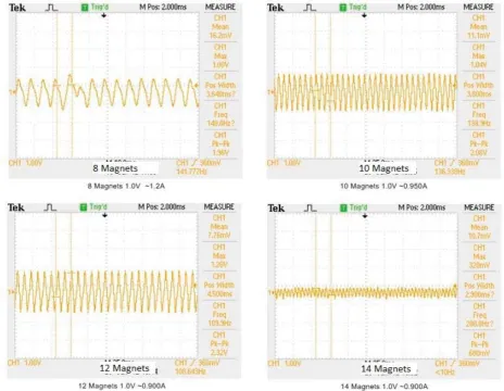
(46) With the data acquired from the tests conducted, it was noted that having more magnets did not necessarily mean better outputs. The output increased when the magnets were increased from 8 to 10 magnets and 10 to 12 magnets. However, increasing the number of magnets from 12 to 14 made the output drop drastically. Figure 3.21 shows the relationship of the number of magnets with respect to the speed of the disc. This showed that for this setup having 12 magnets with alternating poles gave the highest output.. Figure 3.21: Relationship between number of magnets and the speed With the data acquired from the experiment it was noted that the higher the number of magnets the higher the change in the magnetic field strength and direction. This created more flux, which in turn generated more EMF. However, there was a limitation to this concept as having too many magnets very close to each other produced very little flux. As the number of magnets were increased the space between the magnets was reduced. Since the magnets were placed on the disc where they alternate poles, having the magnets too close to each other would cause the output to decrease since, the magnetic field lines of a magnet would go from a magnet into the magnet opposite to it instead of cutting the coil. 35.
(47) Figure 3.22 are the waveforms captured when the disc was spun at 212RPM with 8, 10, 12, and 14 magnets. The waveforms clearly showed that having 12 magnets with alternating poles would give the best output.. Figure 3.22: Waveforms of the outputs with 8, 10, 12 & 14 magnets at a speed of 212RPM. 3.8.3. Placement of magnets Once the number of magnets was decided, experiments were conducted to see if having the magnets on different parts of the disc affected the output. The magnets were placed on two parts of the disc, close to the edge of the disc and in line with the electromagnet. Figure 3.23. 36.
(48) shows the magnets placed in line with the electromagnet, (on the left), and the magnets placed to the edge of the disc (on the right).. Figure 3. 23: Magnets in line with the electromagnet and to the edge of disc. Having the magnet to the edge of the disc, meant that there was an air gap of 4mm between the disc and the edge of the electromagnet. Placing the magnets in line with the electromagnet reduced this air gap from 4mm to 1mm as the thickness of the magnet was 3mm. Further, having the magnets in line with the electromagnet made a closed loop making it easier for the flux to pass through. Figure 3.24 shows a 3D model setup of what this looked like.. 37.
(49) Figure 3.24: Magnet to the edge of disc and Magnet in line with the electromagnet Experiments were run at various speeds with 12 magnets on the disc. The results of these experiments are shown in Table 3.3. Speed. 12 Magnets. 12 Magnets to the. (RPM). (Pk-Pk V). edge (Pk-Pk V). 74. 0.96. 1.12. 95. 1.04. 1.48. 123. 1.64. 1.8. 148. 1.8. 2.13. 176. 2.08. 2.44. 212. 2.32. 2.8. Table 3.3: Peak-Peak voltages of magnets to the edge and in line with the electromagnet. Results showed that both closeness of the magnet to the coil and minimal air gap would give the best output. In this setup one had to be chosen over the other because of the way the electromagnet is designed. Reducing the air gap meant having the magnet away from the coil. Not having the magnet close to the coil meant having a lower output. Since this experiment was looking for what would give the higher output, having magnets to the edge was chosen over having the magnets in line with the electromagnet. Figure 3.26 shows the peak-peak 38.
(50) output voltage with respect to the speed of the disc and figure 3.25 shows the waveforms captured when magnets were placed in line with the electromagnet and when magnets were placed to the edge of the electromagnet.. Figure 3.25: Waveforms for magnet placed in line with Electromagnet to the edge of disc. Figure 3.26: Relationship between magnet placement and speed 39.
Figure


+7


Outline
Related documents
industry, this may imply that funds are domiciled in Luxembourg because the structures necessary to set up such funds already exist in this country and not because of
4 To be able to devise, select, and use modern techniques and tools needed for analysis and solution of complex problems in Electrical and Electronics Engineering applications;
We treated SOA formation from biogenic (monoterpenes and isoprene), lumped anthropogenic and lumped biomass burning volatile organic com- pounds (VOCs) and varied the SOA yield
Next, consider the case of estimating the NLFSR group and the external random number as shown in Fig.8, and deter- mining the internal state and the feedback expression of the
& appropriate math placement test scores or higher level math course with a grade of “C” or better MTH 1410 (4) Calculus I (F, S, Su) Appropriate placement test. scores
section 3 sets out the dangers posed by the hollowing out of democracy, while sections 4 and 5 discuss the growing contestation of human rights, and the disruptive use of
Approval by the master's degree adviser and the department chair is required for independent study, engineering projects, a master's thesis or special topics courses that are
The ISE Department requires that you complete a plan of study approved by your academic advisor even if the courses you plan to select appear on the approved list. To assist
