City, University of London Institutional Repository
Citation
:
Gabdullin, N. and Khan, S. (2016). Electromagnetic and thermal analyses of
high performance magnetic shape memory actuators for valve applications. IEEE
Transactions on Magnetics, 52(9), doi: 10.1109/TMAG.2016.2563406
This is the accepted version of the paper.
This version of the publication may differ from the final published
version.
Permanent repository link: http://openaccess.city.ac.uk/id/eprint/14666/
Link to published version
:
http://dx.doi.org/10.1109/TMAG.2016.2563406
Copyright and reuse:
City Research Online aims to make research
outputs of City, University of London available to a wider audience.
Copyright and Moral Rights remain with the author(s) and/or copyright
holders. URLs from City Research Online may be freely distributed and
linked to.
City Research Online:
http://openaccess.city.ac.uk/
[email protected]
Electromagnetic and Thermal Analyses of High Performance
Magnetic Shape Memory Actuators for Valve Applications
N. Gabdullin1, StudentMember, IEEE, S. H. Khan1, Member, IEEE
1School of Mathematics, Computer Science and Engineering,City University London, London EC1V 0HB, UK
Magnetic shape memory (MSM) alloys are relatively new “smart” alloys which have enormous potential to be used in actuators, sensors and other electrical devices. Their large strain and considerable stress output can be controlled by magnetic fields or mechanical stresses. Maximum magnetic field-induced strain varies from 6 to 12% of the MSM element’s length depending on its microstructure. However, very low operational temperature limit is one of the main drawbacks of conventional MSM alloys. This makes their application in high performance actuators challenging due to considerable power losses. This paper discusses different MSM actuator designs optimized particularly for large force output for pneumatic electromagnetic (EM) valve applications. The thermal problem is addressed through analyzing the heat transfer conditions of each particular design and the effects of different cooling systems. An energy-efficient operating cycle for varying actuator load that takes advantage of the shape memory effect is also proposed. This allows minimization of energy losses resulting in acceptable increase in temperature ensuring stable continuous actuation.
Index Terms—Actuator design, magnetic shape memory alloys, electromagnetic analysis, thermal analysis, smart materials.
I. INTRODUCTION
AGNETIC shape memory (MSM) effect exhibited by certain materials at room temperature is known for almost 20 years now. The most studied MSM alloys are Ni-Mn-Ga alloys which exhibit up to 12% magnetic field induced strain (change in shape) depending on microstructure [1]. A multibillion cycle operation without malfunction [2] along with their “smart” properties make them very promising for application in actuators and sensors. However, Ni-Mn-Ga crystals are very sensitive to temperature and tend to lose the MSM effect at 60-80 C [3], [4]. This is one of the main reasons MSM-based actuators and sensors are still mainly in research and development stage. Considerable thermal loads make it challenging to use MSM elements in compact actuators designed for continuous operation due to large density of energy loss. This is particularly relevant for actuators optimized for large force rather than more studied large strain output actuators [5], [6]. However, large-force MSM actuators are especially promising for application in pneumatic EM valves [7]. An actuator for valve applications producing 5N force output was previously reported in [8]. In this paper we analyze large-force MSM actuator designs for 10N output force which are suitable for long-life EM valve applications. Moreover, thermal stabilization is discussed and the application of energy efficient operating cycle that takes advantage of the shape memory effect is proposed.
II. LARGE-FORCE ACTUATOR DESIGN AND COMPARISON
A comprehensive actuator analysis requires consideration of electromagnetic, mechanical, and thermal problems simultaneously. However, electromagnetic analysis plays the most important role in MSM actuator performance evaluation. It allows definition of main design parameters, such as magnetic circuit geometry, coil size and the input current required for the production of required stress-strain. Unfortunately, at present there is still no well-established design methodology for MSM actuators. In this study the complete actuator magnetic circuit is modelled using the finite element method (FEM) allowing performance evaluation based on electromagnetic field analysis. The actuator output characteristics are calculated using external magnetic field-dependent strain-stress curves published in [9]. The magneto-mechanical behavior of the MSM element in the actuator is taken into account using an approach similar to the one proposed in [10]. This allows the design of MSM actuators taking into account change in MSM permeability which is particularly important for optimal magnetic circuit design [11].
All actuators are designed for magnetic field-induced elongation and mechanical contraction corresponding to operating mode 2 in [12]. A restoring force is produced by a return spring commonly used in MSM actuators. However, mechanical parts are not analyzed in detail in this study. Electromagnetic module in ANSYS Multiphysics is used for solving static magnetic problems using FEM.
The actuators studied are particularly suitable for providing large force rather than maximum possible strain output. Each of the actuators is designed for a required 10N force output with just 0.1mm displacement required in the operating cycle. An additional parameter chosen to be minimized is the total width of the magnetic circuit. This is dictated by a particular design specification to fit multiple actuators along a limited length of space for a particular valve application.
M
Manuscript received:
Corresponding author: N. Gabdullin (e-mail: [email protected])
Color versions of one or more of the figures in this paper are available online at http://ieeexplore.ieee.org.
0018-9464 (c) 2016 IEEE. Personal use is permitted, but republication/redistribution requires IEEE permission. See http://www.ieee.org/publications_standards/publications/rights/index.html for more information.
All actuators work on a 0.5-2.5% partial strain cycle in order to meet an important requirement for long-lifetime actuation, i.e. never reaching a single-variant state [2]. However, an actual load of an actuator varies with strain in pneumatic EM valve applications. Larger force is required to close the valve due to associated air pressure, whereas much less energy is needed for maintaining the final state. Hence, the load of an MSM element in the actuator is considered 2MPa during elongation and 0.5MPa during contraction using corresponding curves in [9]. Since the MSM element in an actuator is also loaded by a spring during elongation, the actuator output is decreased by its compressive stress leading to only 1.5MPa available for external loading. This stress value is used for calculating the output force of an actuator. For the same reason the 0.5MPa curve corresponds to the compressive stress produced only by the mechanical spring.
Fig. 1 HERE
The geometry of the MSM elements used in all the designs in this study is 5 mm 1 mm 6.7 mm. It should be noted that a 0.1 mm output strain is generated due to the elongation of the MSM element from 5 mm to 5.1 mm, whereas a 6.7 mm length in z direction is chosen for force-generating purposes. The width of the MSM element is reasonably minimized due to its contribution to the total reluctance of the air-gap. The maximum magnetic flux density in the air gap of an actuator required for this cycle is 0.61T.
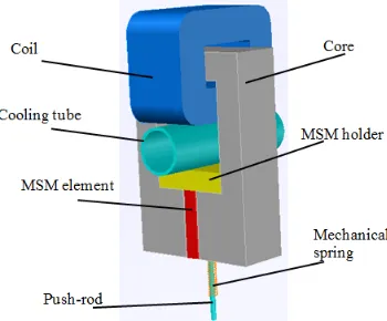
In the first actuator design (design I) the required magnetic field is produced by a coil placed above the MSM element wound around a high-permeable ferromagnetic core made of Radiometal 4550 steel. This configuration seems to be optimal for using short MSM elements with small y-direction height and large z-direction length if the actuator width is to be minimized to ensure large output force.
The actuator designed is shown in Fig. 1 and its parameters are summarized in Table I. A combination of geometric parameters of the coil and the ferromagnetic core that results in the smallest actuator width is found by an iterative optimization process. Saturation of the ferromagnetic core is the main limiting factor for further reduction in the core width. However, there seem to be two further ways of reducing the total valve width. Firstly, a core material with higher permeability and/or saturation flux density can be used. In order to demonstrate the effect of changing the ferromagnetic material, a variation on the first actuator design (design I ) using Hypermco 50 soft magnetic alloy was studied. The increase in saturation flux density from 1.6T to 2.4T allowed the reduction in the core width by more than 30% from 3.7mm to 2.4mm as shown in Table II. This also resulted in about 15% reduction in the total width of the actuator.
Secondly, the geometry of the flux guide can be changed in such a way as to decrease its reluctance. The increase in permeance can be achieved through increasing the cross-section of the yokes. This can be done by increasing the core
length keeping the width to a minimum. In this case, the length of the core becomes much longer than that of the MSM element.
Fig. 2 HERE
However, this means that the magnetic field lines become longer and, hence the reluctance becomes higher. This also gives rise to flux leakage owing to the redistribution of the net magnetic flux part of which goes through the air. Nevertheless, this approach allows a significant reduction in the core width.
The actuator designed is shown in Fig. 2. A comparison of the first two designs (designs I and II in Table I) shows almost 50% decrease in the total width. However, the dependence of coil’s length on core’s length is a major drawback of this design leading to an enormous increase in coil size and, most importantly its electrical resistance leading to increased power loss and heat. Therefore, in this approach a smaller actuator width is achieved at the expense of decreased efficiency due to increased power loss.
In order to avoid the increase in coil resistance, a design approach to increase core permeance without affecting the coil size was developed. In the third design (design III) the MSM element is placed between two coils enclosed within the ferromagnetic core as shown in Fig. 3. The magnetic flux generated by the coils is divided into two halves and ‘conducted’ by two parts of the yoke. Therefore, a smaller core width is required for conducting the same total flux to the MSM element in comparison with the previous designs. This principle was reported previously, e.g. in [13], [14]. However, in the actuator design presented in this paper, the overall increase in permeance is achieved through increasing the core cross-section by increasing the height of the yoke. This allows the design of the core with the smallest width among the discussed designs. Moreover, since the dimensions of the coils are independent of core dimensions, it is possible to optimize these two important parts of the magnetic circuit independently. Therefore, the coils can be kept as small as possible to ensure low resistance and inductance. Thus, this design is much more efficient compared to the previous ones.
Fig. 3 HERE
However, the main drawback of this design is the inevitable proximity of coils to the MSM element. This complicates the shielding of the MSM element from heat generated by coils leaving no room for advanced cooling.
holding the final and initial positions in the operating cycle. Thus the application of an appropriate control algorithm to ensure supply of right currents at the right point on the operating cycle can result in a significant decrease in input power and losses. This is discussed further in the next Section.
TABLE 1 HERE
Fig. 4 shows the output characteristics of first actuator (design I) for two different loading conditions. The 2MPa load corresponds to the nominal 10N output, whereas the 0.5MPa load corresponds to mechanical spring compressive load only. The dashed line shows the actual MSM actuator operating cycle taking into account pneumatic pressure change. Designed actuators are optimized for the largest 10N load during the cycle. Fig. 4 shows that actuators designed for lower loads can be more compact due to less energy required for operation even at a full 6% strain cycle.
Fig. 4 HERE
III. THERMAL ANALYSIS OF MSMACTUATORS
As mentioned above, very low phase transformation temperature of MSM alloys complicates the design of thermally stable actuators. Assuming a 23 C ambient temperature, the 60 C temperature limit for the Ni-Mn-Ga crystals gives a maximum permissible temperature rise of just 37 C without degrading its properties. This is much lower than the temperature rise routinely permissible during nominal operations of many conventional EM actuators [15]. For MSM actuators such a narrow operating temperature range possesses significant challenges given its small dimensions, power density and losses.
The main sources of heat in actuators are electromagnetic and mechanical losses. The electromagnetic losses comprise electrical losses in windings and magnetic losses in the core. Magnetic losses consist of hysteresis and eddy-current losses which are hard to estimate correctly. The total loss can be expressed as:
= + + (1)
Electrical losses are calculated using a well-known equation for Ohmic loss:
= (2)
where Ic is the excitation current in the coil, A and Rc is the
electrical resistance of coils . The accurate estimation of magnetic losses requires detailed transient electromagnetic analysis for a given excitation current, which is not part of this study. Thus, the thermal analysis is conducted assuming that the electric losses are the primary contributors to heat generation in (1). These losses are distributed among coil elements in the FE models.
The heat generated here is mainly transferred through conduction inside the MSM actuator, whereas external heat transfer is determined by convection. Any heat transfer through radiation is neglected since the temperatures involved are too low. The equations describing steady-state thermal conditions can be written as:
=
= ( ) (3)
where q is local heat flux density, W/m2, k
c is thermal
conductivity of the material, W/m K, T is temperature gradient, K/m, Qn is the normal component of heat flux at a
convective surface, W, kf is film coefficient, W/K m2, Ac is
convection surface area, m2, T
s is temperature at the surface of
the box, K and Tamb is ambient temperature, K. These
equations are solved simultaneously using the thermal module in ANSYS Multiphysics. Table II summarizes the thermal properties of elements used in MSM actuator thermal models.
TABLE 2 HERE
As mentioned above, the actuators presented in this paper are designed as EM valves for specific applications in which a very compact arrangement of a large number of such valves within a given narrow space practically insulates a number of their surfaces. Considering this, it is assumed that only front, back, and top surfaces transfer heat by convection (see Fig. 5). This makes the thermal problem especially challenging since the Acterm in (3) decreases.
Fig. 5 HERE
However, it is possible to decrease the temperature of the MSM element by taking advantage of advanced cooling conditions. In this study we consider forced air and water cooling systems. An MSM actuator design utilizing water cooling system was previously reported in [16]. Figs. 1 and 2 show the space available for incorporating cooling windows in designs I and II. This leads to an increase in the overall convective surface area and provides space for water cooling tubes shown in Fig. 6. However, this is not applicable to the design III. It should be noted that convective film coefficient kf
varies widely in literature and can be estimated accurately only for particular setups. kfa=20 for forced air and kfw=300 for
water convection were chosen for modeling purposes.
Fig. 6 HERE
0018-9464 (c) 2016 IEEE. Personal use is permitted, but republication/redistribution requires IEEE permission. See http://www.ieee.org/publications_standards/publications/rights/index.html for more information.
translates into a holding force [17]. This phenomenon is commonly used in “push-push” MSM actuators for maintaining current position [18]. It has been shown in [19] how energy-efficient operating cycle can be developed by taking advantage of the shape memory effect. However, twinning stress is conventionally considered a drawback for other types of MSM actuators due to associated mechanical hysteresis and energy dissipation. On the other hand, the holding force can be used for keeping the valve closed supplying much less current than it is required for elongating the MSM element. A condition for holding a particular position can be written as:
( ) + ( ) > ( ) + ( ) (4)
where tw( ) is twinning stress, MPa, mag(Ic) is magnetic
field-induced stress [20], MPa, comp( ) is compressive stress
produced by a spring, MPa, and load( ) is total external load,
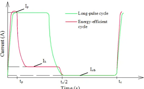
MPa. Decrease in load (pneumatic pressure) at the end of the cycle yields lower electric current required for holding a final position. This crucial detail can be used for decreasing input current significantly when MSM element is fully elongated. Further decrease in input current allows mechanical spring to contract the MSM element. Therefore, the energy-efficient operating cycle consists of three areas corresponding to peak, holding and stand-by current. Fig. 7 illustrates a long-pulse and the energy-efficient cycles.
Fig. 7 HERE
Average power losses are calculated in order to avoid running time-consuming transient thermal analysis for cycles in Fig. 7. This can be expressed with reasonable accuracy using:
= + + (5)
where Ipis pulse (maximum) current, A, Ih is holding current,
A, Istb is stand-by current, A, tp is pulse time, s, th is holding
time, s, tstb is stand-by time, s and tc is duration of one cycle, s.
th is not applicable for the long-pulse cycle. Calculations were
done for 300Hz frequency giving tc=3.3ms. Equation (5)
allows representation of power losses for an inherently transient operating cycle with average power losses which produce the same temperature rise in steady-state thermal analysis.
Table III summarizes the results of thermal analyses conducted for the designs described above for different cooling and excitation conditions. It should be mentioned that thermal simulation is particularly susceptible to uncertainties associated with parameters used for describing material properties and representing interaction with the environment. For instance, thermal conductivities in Table II are average values, whereas deviations that may occur in a given material are not known. All material properties are also assumed linear and homogeneous in the model. However, discretization error
is an additional source of errors in FE models. Regions with rapidly changing geometry (e.g. corners) or material properties (areas connecting different parts of the model) can give rise to considerable numerical errors even for a very fine mesh. While numerical errors cannot be fully eliminated in the analyses conducted, they are kept consistent among different models leading to 0.5% uncertainty in the solution of the thermal problem. This allows adequate comparability of the results obtained.
Table III illustrates the considerable variation of losses among designed actuators and the effect of operating cycles. For example, losses produced by the second actuator are three times larger than those produced by the third actuator. Hence, one should consider the overall actuator efficiency in choosing a particular design since all of them have the same output. However, the use of short pulses decreases losses by 70-86% for 0.5 and 0.2ms pulses respectively. As expected, the long-pulse cycle is the most thermally unfavorable and water cooling is required for reaching thermal stability. The colors in Table III illustrate operational regimes suitable for MSM alloys with 60-80 C transformation temperatures. Use of cooling window has the most significant effect in the second design due to large actuator length and, hence larger convective surface area. The third design requires use of the energy-efficient cycle for stable operation since advanced cooling conditions are not applicable. Table III shows that at least a couple of options for reliable thermal operation for each of the designs are available. However, the use of the energy-efficient cycle is much more advantageous and environmentally friendly since it allows operation of actuators with lower power supply, dissipating less energy into the environment.
TABLE 3 HERE
IV. CONCLUSIONS
with study on thermal characterization of MSM actuators and their cooling conditions.
V. REFERENCES
[1] A. Sozinov, N. Lanska, A. Soroka, and W. Zou, “12% magnetic field-induced strain in Ni-Mn-Ga-based non-modulated martensite,” Appl. Phys. Lett., vol. 102, no. 2, p. 021902, Jan. 2013.
[2] I. Aaltio, Y. Ge, H. Pulkkinen, A. Sjöberg, O. Söderberg, X. W. Liu, and S. P. Hannula, “Crack growth of 10M Ni-Mn-Ga material in cyclic mechanical loading,” Phys. Procedia, vol. 10, pp. 87–93, Jan. 2010. [3] O. Heczko and K. Ullakko, “Effect of Temperature on Magnetic
Properties of Ni – Mn – Ga Magnetic Shape Memory ( MSM ) Alloys,”
IEEE Trans. Magn., vol. 37, no. 4, pp. 2672–2674, July 2001. [4] E. Pagounis, R. Chulist, M. J. Szczerba, and M. Laufenberg,
“High-temperature magnetic shape memory actuation in a Ni–Mn–Ga single crystal,” Scr. Mater., vol. 83, pp. 29–32, July 2014.
[5] X. Zhao, S. Wang, and X. Zhao, “Operation principle and characteristic of magnetically controlled shape memory alloy actuating device,” in
Proc. ICETCE, Apr. 2011, pp. 6730–6734.
[6] K. Matsunaga, N. Niguchi, and K. Hirata, “Study on Starting Performance of Ni-Mn-Ga Magnetic Shape Memory Alloy Linear Actuator,” IEEE Trans. Magn., vol. 49, no. 5, pp. 2225–2228, May 2013.
[7] S. Flaga, J. Pluta, and B. Sapinski, “Pneumatic Valves Based on
Proc. 12th ICCC, May 2011, pp. 111–114.
[8] D. Ireneusz and S. Flaga, “Characteristics of the flow control valve with MSMA actuator,” in Proc. 15th ICCC, May 2014, pp. 192–195. [9] E. Pagounis and P. Müllner, “Recent Developments in Magnetic Shape
Memory Actuation,” in Proc. Actuator, June 2014, pp. 86–91. [10] T. Schiepp, M. Maier, E. Pagounis, A. Schlüter, and M. Laufenberg,
“FEM-Simulation of Magnetic Shape Memory Actuators,” IEEE Trans. Magn., vol. 50, no. 2, p. 7024504, Feb. 2014.
[11] N. Gabdullin and S. Khan, “Effects of Varying Permeability of Magnetic Shape Memory (MSM) Alloys on Design and Performance of Actuators,” Presented at CompuMag 2015. [Online]. Available: http://www.compumag2015.com/Pdfs of Short Papers by Session/PD2%5CPD2-2 Gabdullin-Effects of Varying Permeability of Magnetic Shape Memory.pdf.
[12] B. Holz, L. Riccardi, H. Janocha, and D. Naso, “MSM Actuators: Design Rules and Control Strategies,” Adv. Eng. Mater., vol. 14, no. 8, pp. 668–681, Aug. 2012.
[13] J. Tellinen, I. Suorsa, I. Aaltio, and K. Ullakko, “Basic Properties Of Magnetic Shape Memory Actuators,” in Proc. Actuator, June 2002, pp. 10–12.
[14] L. Riccardi, D. Naso, H. Janocha, and B. Turchiano, “A precise positioning actuator based on feedback-controlled magnetic shape memory alloys,” Mechatronics, vol. 22, no. 5, pp. 568–576, Aug. 2012. [15] G. Stone, I. Culbert, E. Boulter, and H. Dhirani, Electrical Insulation for
Rotating Machines: Design, Evaluation, Aging, Testing, and Repair, 2nd ed. USA: Wiley-IEEE Press, 2014.
[16] L. E. Faidley, M. J. Dapino, G. N. Washington, and T. A. Lograsso, “Modulus Increase with Magnetic Field in Ferromagnetic Shape Memory Ni-Mn-Ga,” J. Intell. Mater. Syst. Struct., vol. 17, no. 2, pp. 123–131, Feb. 2006.
[17] L. Straka, N. Lanska, K. Ullakko, and A. Sozinov, “Twin microstructure dependent mechanical response in Ni–Mn–Ga single crystals,” Appl. Phys. Lett., vol. 96, no. 13, p. 131903, Apr. 2010.
[18] B. Spasova, M. C. Wurz, C. Ruffert, J. Norpoth, and H. H. Gatzen, “Using Magneto-Optical Measurements for the Evaluation of a Hybrid Magnetic Shape Memory (MSM)-Based Microactuator,” IEEE Trans. Magn., vol. 46, no. 6, pp. 2256–2259, June 2010.
[19] L. Riccardi, T. Schiepp, B. Holz, M. Maier, H. Janocha, and M. Laufenberg, “A Modular, Energy Efficient Actuator Based on Magnetic Shape Memory Alloys,” in Proc. Actuator, June 2014, pp. 112–115. [20] L. Straka and O. Heczko, “Superelastic Response of Ni–Mn–Ga
Martensite in Magnetic Fields and a Simple Model,” IEEE Trans. Magn., vol. 39, no. 5, pp. 3402–3404, Sept. 2003.
N. Gabdullin (S’13) received his M.Sc. degree (first degree) with Distinction in electrical engineering, electromechanics and electrotechnologies in 2012 (2006-2012) from National Research University "Moscow Power Engineering Institute", Moscow, Russia.
He is currently a PhD candidate in electrical and electronic engineering at the School of Mathematics, Computer Science and Engineering at City University London, London, UK. His research interests include electromagnetic field analysis using numerical techniques such as FEM and its application to studying magneto-mechanical behavior of MSM alloys, MSM actuator design and optimization, and thermal characterization of electromagnetic devices.
S. Khan (M’90) received his M.Sc. degree (first degree) with Distinction in electromechanical engineering in 1983 (1977-1983) from Peter the Great St Petersburg Polytechnic University (SPPU, formerly Leningrad Polytechnic Institute), St Petersburg, Russia. He started his Ph.D. research at the same institution in 1984, defended his thesis in 1987 and received the Ph.D. degree in electrical engineering in 1988.
He has been with the School of Mathematics, Computer Science and Engineering at City University London since 1989 where he is a Professor of Instrumentation and Sensors. He is an active member of the Photonics and Instrumentation Research Centre in the School. The Centre has a proven track record for innovative and applied research in collaboration with UK industry, especially in areas of CAD and mathematical modeling of sensors and electromagnetic actuators for nearly three decades. His current research interests include mathematical modeling and CAD of sensors, instruments and devices, computational electromagnetics, finite element modeling and numerical methods, forward and inverse problems in tomographic imaging.
0018-9464 (c) 2016 IEEE. Personal use is permitted, but republication/redistribution requires IEEE permission. See http://www.ieee.org/publications_standards/publications/rights/index.html for more information.
[image:7.595.302.543.86.258.2]
Fig. 1. Magnetic field distribution in the magnetic circuit of the first designed actuator (design I). The red circle (in color) shows the position of the MSM element. The MSM element elongates in the vertical direction. Surrounding air is hidden in all figures.
Fig. 2. Magnetic field distribution in the magnetic circuit of the second designed actuator (design II). The red circle (in color) shows the position of the MSM element. The MSM element elongates in the vertical direction.
Fig. 3. (a) Isometric and (b) upper view of the magnetic field distribution in the magnetic circuit of the third designed actuator (design III). The red circles (in color) show the position of the MSM element. The MSM element elongates in the vertical direction.
Fig. 4. Output characteristics of first actuator (design I) under constant 0.5 MPa and 2 MPa (10N) pressure levels. Dashed line shows actual varying load cycle combining 2MPa elongation and 0.5MPa contraction.
Fig. 5. (a) Temperature distribution and (b) convection conditions in 3D thermal model of the second actuator design (design II) with no cooling windows.
Fig. 6. First actuator design (design I) with a water tube in the cooling window.
(a) (b)
2.0 1.8
1.6 1.4
1.2
1.0 0.8
0.6
0.4 0.2B (T)
1.89 1.69
1.49 1.28
1.08
0.87 0.67
0.46
0.26 0.05B (T)
1.9 1.7
1.5 1.3
1.1
0.9 0.7
0.5
[image:7.595.65.280.92.269.2] [image:7.595.309.544.299.415.2] [image:7.595.63.281.318.478.2] [image:7.595.316.491.458.603.2] [image:7.595.73.286.518.686.2]Fig 7. Schematic illustration of long-pulse and energy-efficient operating cycles.
TABLE I
Comparison of MSM Actuator Design Parameters I I II III Core material Ra Hb R R
Core width, mm 3.7 2.4 1.2 0.7 Total width, mm 11.9 9.8 6.4 6.6 Number of coil
turns 140 154 110 104 Resistance, ohm 0.64 0.72 1.34 0.44
aRadiometal 4550 bHypermco 50
TABLE II
Thermal Properties of Materials Used in the MSM Actuator Models Material Thermal conductivity kc, W/m K Core (Radiometal 4550) 13
MSM element 16 Coil (copper) 385 Coil (insulation) 0.4 Mechanical Parts 17
TABLE III
Temperature Dependence of the MSM Element in the Actuators Studied with Excitation and Cooling Conditions
Conditions
Designs Ia Ib Ic IIa IIb IIc IIIa IIIb IIIc
Power Loses, W 2.9 0.9 0.4 6 1.9 0.8 2 0.6 0.3 No cooling window, air
cooling
166 67 41 391 137 71 210 80 47
Cooling window, air cooling 155 64 40 193 77 45 - - - Cooling window, exterior air
cooling, interior water cooling
71 38 29 42 29 26 - - -
atp=tc/2long-pulse, btp=0.5 ms pulse, ctp=0.2 ms pulse
[image:8.595.55.291.85.232.2]