City, University of London Institutional Repository
Citation
:
Bremer, K., Wollweber, M., Guenther, S., Werner, G., Sun, T., Grattan, K. T. V. &
Roth, B. (2014). Fibre optic humidity sensor designed for highly alkaline environments.
Proceedings of SPIE - The International Society for Optical Engineering, 9157, A4. doi:
10.1117/12.2059637
This is the accepted version of the paper.
This version of the publication may differ from the final published
version.
Permanent repository link:
http://openaccess.city.ac.uk/14529/
Link to published version
:
http://dx.doi.org/10.1117/12.2059637
Copyright and reuse:
City Research Online aims to make research
outputs of City, University of London available to a wider audience.
Copyright and Moral Rights remain with the author(s) and/or copyright
holders. URLs from City Research Online may be freely distributed and
linked to.
City Research Online:
http://openaccess.city.ac.uk/
publications@city.ac.uk
Fibre optic humidity sensor designed for highly alkaline environments
K. Bremer*
a, M. Wollweber
a, S. Guenther
b, G. Werner
b, T. Sun
c, K.T.V. Grattan
c, B. Roth
aa
Hannover Center for Optical Technologies (HOT), Leibniz Universitaet Hannover, Hanover
Germany;
bFibotec Fiberoptics GmbH, Meiningen, Germany;
cSchool of Engineering and
Mathematical Sciences, City University London, London, United Kingdom
ABSTRACT
This paper presents the design of a sensor packaging for a Fibre Bragg Grating (FBG) based fibre optic humidity sensor. The evaluation of the developed fibre optic sensor was performed under experimental conditions and verified its capability to withstand highly alkaline environments. Therefore, the sensor can be applied to monitor the concrete humidity level and thus to indicate the maintenance of concrete structures.
Keywords: structural health monitoring, FBG, humidity, temperature
1. INTRODUCTION
The level of humidity strongly influences the lifetime of concrete as different types of degradation mainly depend on the pore water content of the concrete [1]. For instance, a fast setting of the concrete might cause a high pore density and thus reduce the stability of the concrete sample. Furthermore, the carbonation of concrete, which reduces or even eliminates the passivation of the steel reinforcement and therefore makes it more likely to corrode, mainly takes place in an aqueous phase. Also thermally induced damages, e.g. in the case of fire or frost, are critical for the stability of the concrete. Consequently, in order to indicate the service time of the concrete the monitoring of humidity level is essential. Fibre optic sensors have the inherent advantages of being electrically passive, easy to multiplex as well as capable to operate remotely. In the past several different approaches of fibre optic moisture sensors based on Fibre Bragg Gratings (FBGs) have been reported [e.g. 2]. In order to use FBGs for humidity sensing they have to be coated with a moisture sensitive polymer. This polymer then interacts with humidity and swells, which leads to an axial and radial strain in the fibre and, thus, the FBG. For instance Polyimide (PI) can be used as a moisture sensitive polymer. It is hygroscopic and swells in aqueous media. In the past PI coated FBG based fiber optic humidity sensors have been successfully used to measure the moisture absorption of concrete structures [3] as well as masonry structures [4, 5]. However, the highly alkali environment inside the concrete degrades the PI coating and hence reduces the performance of the PI coated FBG based fiber optic humidity sensor with time [6]. Therefore, in this paper a sensor packaging for a FBG based fiber optic humidity sensor is designed and evaluated. The sensor packaging contains a PTFE membrane that protects the PI coating of the fiber optic humidity sensor against alkaline solutions.
2. TECHNICAL DESCRIPTION
Background
The fibre optic sensor consists of two Fibre Bragg Gratings, which are multiplexed along a single optical Single Mode (SM) fibre, as shwon in Fig. 1. A FBG coated with a moisture sensitive polymer (PI coating) is used for humidity sensing. In order to compensate the cross-sensitivity of the polymer coated FBG a second bare FBG is used for temperature measurements. Light travelling to the fibre optic sensor is reflected at the first and second FBG at wavelengths equal to the respective Bragg wavelengths λB01 and λB02. All other wavelengths propagate through the optical SM fibre.
The shift of the Bragg wavelength of a bare FBG due to temperature can be calculated as [2]:
>
(1-P ) +@
T Ta11 e
1
1 ' '
'
[ D O
O
B
B , (2)
Light
SM-Fibre
Polyimide
y
Bare FBG Polyimide
coated FBG
Thread PTFE Membrane Perforations
/
...:_!....+4 ....1. 4...4...4 ,
\
[image:3.612.176.436.80.157.2]PEEK housing
Figure 1. Schematic of the fibre optic humidity sensor
where Pe, αand ξ are the photoelastic constant, the thermal expansion coefficient of the fibre and the fibre-thermooptic
coefficient [2]. Furthermore, the humidity and temperature sensitivity of the polymer coated FBG can be expressed as [2]:
>
(1-P ) +@
T (1-P ) RH RHa T
a21 22 e e RH
2
2 ' ' ' '
' D [ D O O T B
B , (3)
where αT and αRH are the thermal and moisture expansion coefficients [2]. By using the humidity coefficient (a22) and
temperature coefficients (a11, a21) from both FBGs in Equation 2 and Equation 3, a matrix equation can be constructed as:
» ¼ º « ¬ ª ' ' » ¼ º « ¬ ª » » » » ¼ º « « « « ¬ ª ' ' RH T a a B B B B 22 21 11 2 2 1 1 0 a O O O O
. (4)
The matrix equation in Equation 4 can be inverted and hence the applied humidity/temperature can be determined.
Fabrication
Both FBGs were inscribed into a fibercore PS1250/1500 optical SM fibre using a KrF excimer laser using the phase mask technique. Subsequently the fibercore optical fibre was tempered at 200°C for three hours to avoid any thermal drifting of the FBGs later. Then one FBG was coated with polyimide (Pyralin PI 2525) using the dip coating technique [2]. In order to enhance the bonding between the polyimide coating and the optical fibre, the second FBG was first treated with 3-aminopropyltriethoxysilane (3-APTS) solution (0.1%) diluted with deionised water [2].
Packaging
[image:3.612.89.521.502.600.2]In order to protect the FBG based humidity sensor an appropriate sensor packaging was developed. At first the optical fibre comprising both FBGs was embedded into a tube made of PEEK and perforated at the tip. The perforated tip ensures that water vapour reaches the PI coated FBG. The perforated tip was then covered using a permeable PTFE membrane to protect the sensor against dirt and chemicals [6]. Finally the PTFE membrane and the PEEK tube were covered again using a perforated PEEK rod with a centrically bore hole. The packaged FBG based humidity sensor is shown in Fig. 2.
Figure 2. Schematic of the housing (a) and picture of the packaged fibre optic humidity sensor (b).
80
70
-..-....60
x
IX 50 d
@ 40 'I
30
20
I
@20°C e
@40°C ©60°C
I
A20 30 40 50 60
Applied RH (%)
70 80
1.0
0.8
0.6
0.4
0.2
0.0
0 20 40 60 80 100 120 140 160
Time (min)
1547.6
1547.5 E
m1547.4
'ili
3 1547.3
Á 1547.2
m
1547.1
20 30 40 50 60 70
Relative Humidity ( %)
80
1537.5
ti
0 1537.3
1537.2
-0- before +after
20 30 40 50 60 70
Relative Humidity (%)
80
3. EVALUATION
The packaged FBG based humidity sensor was evaluated using a FBG interrogator consisting of a broadband light source (Opto-Link ASE light source), a 3dB coupler and a spectrometer (Ibsen I-Mon E). At the beginning the humidity response of the FBG based humidity sensor was evaluated at different temperatures. In Fig. 3a the humidity readings at different temperatures of the sensor are shown after the sensor was calibrated using a climate chamber (Memmert CTC256). As shown in Fig. 3a the FBG based humidity sensor has a linear response to humidity independent of the ambient temperature. Following this, the response time of the packaged fibre optic sensor was measured. Initially the sensor was kept at constant temperature (20°C) and humidity (20% RH) followed by immersing the packaged sensor in water. The obtained step response of the packaged sensor was compared to an unpackaged FBG based humidity sensor. Both step responses are shown in Fig. 3b. It is evident from Fig. 3b, that the packaging has no influence on the response time.
Figure 3. (a) Response of the packaged fibre optic humidity sensor to humidity at different temperatures. (b) Response times of a bare and packaged fibre optic humidity sensor.
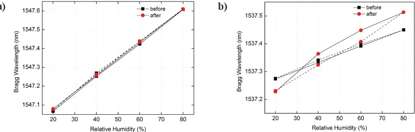
[image:4.612.90.515.203.351.2]Finally the alkaline resistance of the sensor packaging was tested. An alkaline solution was obtained by 0.75 M KOH and 0.75 M NaOH in a 10% CaOH solution [6]. The pH value of this alkaline solution was 13.4, which was measured using a pH- meter (Hach HQ40d). A packaged and a bare fibre optic humidity sensor were both immersed for 22h in the alkaline solution. In Fig. 4a and Fig. 4b the sensors responses to different humidity levels at constant temperature (20°C) are shown. According to Fig. 4a the sensor packaging can withstand high pH concentrations and therefore can protect the sensor against alkaline pore water. On the other side, the response of the bare fibre optic sensor changed dramatically after the sensor was immersed in the alkaline solution. Also the bare sensor shows a hysteresis now, which was not observed before.
Figure 4. Alkaline resistance of a packaged (a) and unpackaged (b) fibre optic humidity sensor. Data shown are taken before (black) and after (red) exposure to the alkaline solution. The packaged sensor shows no degradation due to the high pH solution.
a)
b)
[image:4.612.85.506.471.605.2]4. SUMMARY
In this paper a packaging for a fibre optic humidity sensor was reported. The evaluation verified that the packaging is able to protect the sensor in a highly alkali solution (13.4 pH). The designed fibre optic sensor shows a linear response to humidity and is insensitive to temperature variations. Furthermore, the response time of the packaged sensor is identical to that of a bare fibre optic humidity sensor. Therefore the packaged sensor can be applied to measure humidity within concrete structure and thus to indicate their maintenance.
Acknowledgements
The authors acknowledge support of the Bundesministerium für Wirtschaft und Energie (BMWi) - Zentrales Innovationsprogramm Mittelstand (ZIM) within Grant Number VP2672502UW1. The support of the George Daniels Educational Trust for KTVG is gratefully acknowledged.
REFERENCES
[1] Wiese, S. et al, „Neuartige faseroptische Feuchtesensoren zur zerstörungsfreien Langzeitüberwachung von
Betonbauwerken“ Feuchtetag '99: Umwelt - Meßverfahren - Anwendungen, DGZfP-Berichtsband BB 69-CD, Vortrag M4, BAM, Berlin-Lichterfelde (1999)
[2] Yeo, T.L., et al.“Polymer-Coated Fibre Bragg Grating for Relative Humidity Sensing”, IEEE Sensors Journal,
5, 1082-1089 (2005)
[3] Yeo, T.L. et al“Demonstration of a fibre-optic sensing technique for the measuring of moisture absorption in
concrete”, Smart Mater. Struct.,15, N40-N45 (2006)
[4] Sun, T. et al “Optical fibre humidity sensor design for building stone condition monitoring”, Proc. IEEE Sensors 2010, 1135 - 1139 (2010)
[5] Sun, T. et al “Building Stone Condition Monitoring Using Specially Designed Compensated Optical Fiber Humidity Sensors”, IEEE Sensors Journal, 12, 1011-1017 (2012)