ContentslistsavailableatScienceDirect
Sensors
and
Actuators
A:
Physical
jo u r n al h om ep a g e :w w w . e l s e v i e r . c o m / l o c a t e / s n a
Micro-tweezers:
Design,
fabrication,
simulation
and
testing
of
a
pneumatically
actuated
micro-gripper
for
micromanipulation
and
microtactile
sensing
夽
A.F.
Alogla,
F.
Amalou,
C.
Balmer,
P.
Scanlan,
W.
Shu
∗,
R.L.
Reuben
SchoolofEngineeringandPhysicalSciences,Heriot-WattUniversity,Edinburgh,UnitedKingdom
a
r
t
i
c
l
e
i
n
f
o
Articlehistory:
Received1November2014
Receivedinrevisedform25June2015
Accepted25June2015
Availableonline20July2015
Keywords:
Micro-gripper Pneumatic Micromanipulation
Finiteelementanalysis
Tactilesensing
a
b
s
t
r
a
c
t
Thispaperpresentsanovelmicro-gripperdesignwiththedualfunctionsofmanipulationandforce sensing.Thedeviceconsistsoftwoparallelplates,eachmountedontorsionbars,whichcanbemade torotatetowardsorawayfromeachotherbyuseofapneumatically-orhydraulically-actuatedelastic membrane.Theplatescanbeconvenientlyfabricatedusingphoto-etchingandthedesignallowsfora rangeofratiosbetweenactuationpressureandtipopeningdisplacementandforce.Theelasticgripping tipscanbedesignedtoprovidesufficientcompliancethattheirstraincanbeusedtomonitorandcontrol thegrippingforce.Anexemplardevicehasbeenfabricatedanditsbehaviourcharacterisedbyaseriesof mechanicalmeasurementsofforceanddisplacement.Thesemeasurementshavebeenrationalisedusing asimpleanalyticalmodel,backedupwithfiniteelementanalysistoemphasisethedesignvariables andscalability.Thisexemplardevice,withamaximumtipopeningamplitudeof1mmandmaximum forceoutputof50mN,hasalsobeendemonstratedtoperformpick-and-placeoperationswith200m micro-beads.
©2015TheAuthors.PublishedbyElsevierB.V.ThisisanopenaccessarticleundertheCCBYlicense (http://creativecommons.org/licenses/by/4.0/).
1. Introduction
Therapid evolution in thebiological sciences hasledto an increasedrequirementformanipulatingentitiesatthemicro-and nano-scale. In general, manipulating biological objects such as singlecells, micro-beadsor evenembryoscanbeclassifiedinto contactandnon-contacttechniques.Thenon-contacttechniques are mainlyoptically-based [1–4], where a highly focused laser beamisusedtotrapandmoveabiologicalmicro-object.Although theperformanceofsuchtechniquesissatisfactory,sophisticated andexpensiveopticalsetupsarerequired [5]and theexposure toopticalradiationmayhavelongtermnegativeeffects onthe manipulatedmicro-objects[6].
Micro-pipettesandgrippersarethemostcommonlyused con-tacttechniquesformanipulatingbiologicalmicro-objects.Pipettes useanegativepressureappliedthroughanozzlebut,despiteits capability to manipulate single cells, this technique requires a highlyskilledusertoachievethemanipulationwithoutdamage tothecellsasitisnotpossibletoveryaccuratelycontroltheforces
夽 SelectedpaperspresentedatEUROSENSORS2014,theXXVIIIeditionofthe
conferenceseries,Brescia,Italy,September7–10,2014.
∗Correspondingauthor.Tel.:+441314518165.
E-mailaddress:[email protected](W.Shu).
actingontheobjectbeingmanipulated.Furthermore,pipetteshave limitedversatilityand,ifcellsaresmallerthantheopeningofthe pipettenozzle,severalcanbedrawnintothepipetteratherthan isolatingjustone[7].Micro-grippersshowmuchgreater versatil-itytomanipulatearangeofobjectsizesandalsothepossibility
of controlling and measuring theforces acting on the gripped
objects.
Micro-grippersarecomplexmicro-electro-mechanical-systems (MEMS)[8]andcanbecategorizedaccordingtotheiractuation mechanism:electrostatic,shapememoryalloy(SMA),magneticor piezoelectric,eachofwhichhasitsadvantagesanddisadvantages. Electrostaticactuationgeneratesasatisfactoryamountofoutput force[9]butisdifficulttooperateinion-richliquids(e.g.bodyfluids
[10]).SMAactuators,whileproducingahighforceand displace-ment,areproblematicinliquidenvironmentsduetotheheatloss associatedwiththehighsurface-to-volumeratioofmicrodevices whichmaydamagethebiologicalsurroundings[10].Furthermore, thedisplacementsofSMAsarehardtocontrolbecauseoftheir ther-momechanical nonlinearities [11]. Piezoelectricactuation offers
highspeed and good motionresolution [12] but actuation
dis-placementsarelimited[13]andtherequiredappliedvoltagescan damagebiologicalsystems.Duetothedisadvantageousscalingof
magneticfields,magneticmicroactuatorshavelow forceoutput
andtheirperformanceisalsolimitedbecauseofthermal dissipa-tionbytheconductivematerialsandthepossibilityofsignificant
http://dx.doi.org/10.1016/j.sna.2015.06.032
A.F.Aloglaetal./SensorsandActuatorsA236(2015)394–404 395
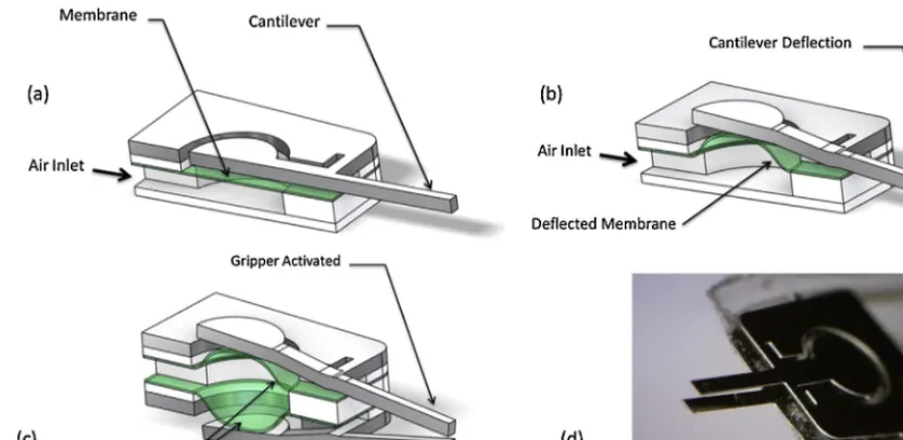
Fig.1. Schematicdrawingsofworkingprincipleofthegripperdevice(a–c),andpictureofassembledmicro-gripper(d).
electricalleakagecurrents.Also,magneticfieldscanposeproblems inthebiologicalenvironments[14].
Fluidicmicroactuators,withtheirhighforceandpower densi-ties,havebeenwidelyadvocatedformanipulatingpreciseamounts
of liquid within microfluidic and micro total analysis systems
(TAS)[15,16].Theactuationcanbeeitherpneumaticorhydraulic,
and can therefore operate in liquid environments for
biologi-calcellmanipulation[17–19].Althoughtherearerelativelyfew studies of this type of actuator it has been demonstrated that
pneumaticactuators havethepotentialtoproducesomeofthe
highest force and power densities of actuation options at the
microscale[15].Highperformancepneumaticmicro-grippercan befabricatedusingmicro-stereolithography[20]orlasercutting
[21].Despitetheadvantagesofthistypeofactuator,designs typi-callyrequirecomplex3-dimensionalfabricationor3-dimensional assemblytechniquesandhencelimitedthepossibilityfor large-scaleproduction.Thispaperreportsthedesignofamicro-gripper
with a simple method of manufacture and assembly that has
the potential to scale to the level of manipulating a single
biological cell. The main design challenge is to achieve accu-ratecontrolover theopeningandclosing states ofthegripper,
along with the gripping forces, which has been addressed by
a compliant gripper design offering the opportunity for force
feedback and two-way actuationallowing opening and closing
actions.
1.1. Micro-gripperdesignandfabrication
Themicro-gripperdescribedhereispneumaticallyactuatedand isdesignedtobeoperatedinarangeofenvironments,including airandliquid,atarangeofscales.Itcomprisestwomainparts; theactuationmechanism andtheflexible gripperarms(Fig.1a andb).Theactuatorisessentiallyaflexiblemembranethatapplies forcetothegripperpadwhentheairinletispressurised.The grip-perplatewascutfromstainlesssteelsheet(50minthickness, GoodfellowUKLtd)usingaphoto-etchingtechnologytogivean
outerenvelope,whichwassandwichedbetweentwoPMMA(poly
methylmethacrylate)layers.Whenpressureisappliedtothepad, thearmspivotaroundatorsionalspringconsistingofabar-shaped ligamentofthegripperplate.Thearmsthemselvesaredesigned tobeflexiblesothatthegrippingforcecan,inprinciple,be mon-itoredbymeasuringthestrainatthepivotendofthearmorthe slopeatitsfreeend.Thedesigncanbeoperatedwithtwoarms
closingtogetherwhenactuated(asshowninFig.1c)orwithone armbearingontoeitherafixedplateorasamplesurface(asshown inFig.1c).Itcanalsobeactuatedinthereversedirectionsothatthe jawsareopenedbyactuatorsontheoppositesidesofthegripper platesusingthespringforceandcomplianceofthearmstoofferthe grippingforce,limited,ifnecessary,bytheairpressure.Thewhole designisscalablebycontrollingthedimensionsofthecomponents ofthegripper,inparticularthearmsandtorsionbars.
Thismicro-gripperisassembledwithmultilayers(inFig.2)of thinPMMAsheet(200minthickness,EMKAYPlasticsLtd),elastic siliconemembrane(50minthickness)anddouble-sided adhe-sivesheet(50m,3MUKPlc),whicharefabricatedusingaCO2
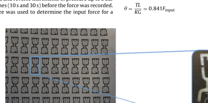
lasersystem[22].ThisdeviceisassembledbycoatingthePMMA withdoublesidedadhesiveandthenlasercuttingthelayers.These layersarethenmanipulatedbytweezersintothecorrectposition. Thewholedeviceisthencoveredinlaminatefilmandheatedto ensurenochanceofleaks.Theassemblyofthisdeviceisa sim-pleandcosteffectivemethodofmanufactureofamicro-gripper, theuseoflayersalsolendsitselftolargescaleproduction,Fig.3, andadditionallayerscanofferfurtheractuationoptions,suchas channelsforgripperclosing.
2. Performanceofprototypedevice
Tovalidatetheabove-mentioneddesignprinciples,aprototype devicewasrealisedin50mthickstainlesssteelsheetwithapad diameterof2mm,armsoflength3mmandbreadth0.45mm,and torsionbarsofbreadth0.3mmandlength0.625mm.The perfor-manceofthedevicewasevaluatedusingtwotests;adynamictest wherethefeedairpressurewaspulsedatarangeoffrequencies andpressuresandthetipdisplacementwithnoloadingwas mea-sured,andastatictestwheretheinputpressureandoutputload
weremeasured.
Forthedynamictest,anopticalsensorwasusedtoobtainthe deflectionatthecantilevertipusingasimilarapproachtoanAFM wherealaserbeamatafixedangleisreflectedfromtheendofthe cantileverandthepositionofthespotonaphotodetectorrecorded,
Fig.4(a).Thedeflectionwascalculatedfromthevoltageofthelaser usingthegeometryoftheexperimentalsetup[24].Deflectiondata wereacquiredusingaLabViewcontrolinterfaceatarateof300 samplespersecondforarecordlengthofaround20cycles(e.g.
[image:2.646.94.510.58.260.2]Fig.2.Assemblysteps.
theelasticityofthepressurefeeddampenstepressureoscillation andfrequenciesabove50Hzareoflittlemeaning.
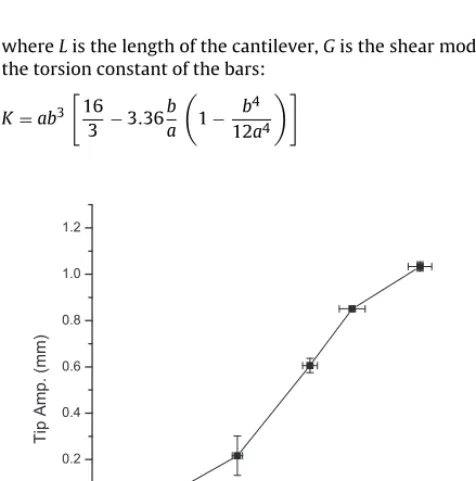
Therelationbetweenthedeflectionofthemicro-gripperpad andmicro-grippertipisanimportantdesignconsiderationsinceit informsthetorsionalstiffnessofthepivotbarsaswellasthetip sensitivitytogrippingforce.Thisrelationwasmeasuredusinga modificationofthedynamicset-upshowninFig.4(a),wherethe deflectionofthepadandthetipweremeasuredinseparate exper-imentsforpressurepulsesto0.17,0.35,0.56and0.76bar,allata frequencyof1Hz.Fig.5showsthemeanandstandarddeviationof theamplitudesoftipdisplacementandpaddisplacementforeach ofthepressuresplottedagainsteachother.
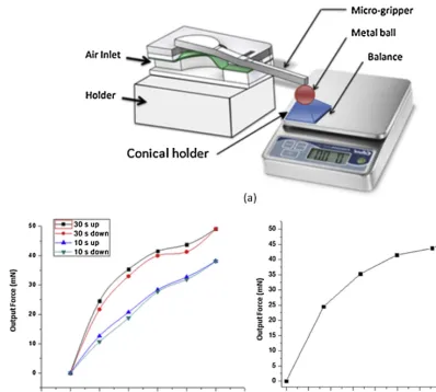
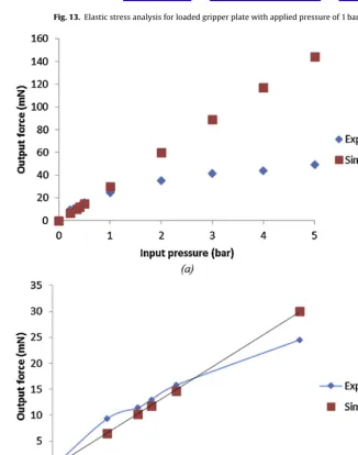
Forthestatictests,adigitalbalancewithread-outuptofour dec-imalplaces(ingrammes)wasusedtomeasuretheforcegenerated atthetipofthecantilever.Thetipwasbroughtintocontactwith a1.5mmdiametermetallicballmountedonalightweightconical holderasshownschematicallyinFig.6(a).
Thepressureinthefeedlinewasthenincreasedincrementally to5bar,recordingtheoutputforceatapproximately0.2,0.3,0.4,0.5 and1bar,andthereafterat1barintervals.Theresultsareshownin
Fig.6(b)forforwardandreverseincrementsofpressureupto5bar usingtwodwelltimes(10sand30s)beforetheforcewasrecorded. Thesameprocedurewasusedtodeterminetheinputforcefora
givenpressurebyapplyingthemembranedirectlytothemetal
ballandrecordingtheforceatthesameincrementsofpressure.
Fig.6(c)showstherelationshipbetweentheinputforceasdefined bytheinputpressureandtheoutputforce,determinedfromthe massexertedonthebalance,foreachofthepressureincrements.
3. Analyticalmodel
Inordertoselectappropriatedimensionsforatactilegripperof thetypepresented,itisusefultohaveasimpleanalyticalmodelfor thestiffnessesofitskeyparts.Fig.7showsasimplifiedmechanical modelofthegripperpad-armplate,withtheinputforce,theoutput reactionandthetorsionalsprings(Fig.8).
When the cantilever tip is not in contact with an object
(Routput=0),theinputforcedeterminesthereactiontorque:
T=2.35Finput,
foraninputforceinNandtorqueinNmm.Forsmalldisplacements, theangulardisplacementatthebarscanbewrittenintermsofthe dimensionsoftheplate:
= TL
KG =0.841Finput
[image:3.646.102.485.54.266.2] [image:3.646.113.472.551.729.2]A.F.Aloglaetal./SensorsandActuatorsA236(2015)394–404 397
Fig.4.(a)Dynamictestset-upwithopticalsensor,(b)Typicaldynamictestoutputfromopticalsensor,(c)amplitudeoftipdisplacementasfrequencyisvariedfordifferent
pulsedpressures.
whereListhelengthofthecantilever,Gistheshearmodulusand thetorsionconstantofthebars:
K=ab3
16 3 −3.36
b a
1− b4
12a4
-0.2 0.0 0.2 0.4 0.6 0.8 1.0 1.2
-0.2 0.0 0.2 0.4 0.6 0.8 1.0 1.2
Ti
p
Amp
.
(mm
)
Pad Amp. (mm)
Fig.5.Relationbetweenmeasuredpadandtipdeflectionsforpressurepulse
ampli-tudesbetween0.1and0.75bar.
and2aand2baretheshortandlongdimensionsofthetorsionbar cross-sections.
The expected tip displacement for a given angle is
ıarm=larmtan=larmtan(0.841Finput)mm and, for a simple
tor-sionpivot(i.e.nobending),thedisplacementsatthepadandat thecantilevertipfor agivenangle(i.e.agivenpressure)might thereforebeexpectedtoberelatedıcantilever,T =lcantileverlpad ıpad,T
Aswellascausingtheabovedisplacements,aninputforcemight
beexpectedtointroducecertainamountofbendinginthepad
arm,dependingonthetorsionalspringstiffness,alsobendingin thecantileverarm,dependingonthereactionforceofthegripped object.Toafirstapproximation,thepaditselfcanbeassumednot
tobendsothatthebendingcomponentofthepaddisplacement
canbetakenastheenddeflectionofacantileveroflengthLwhere theloadplusanadditionalappliedmomentMinput=Finput(L−l)is
appliedadistancelfromthefixedend.Therelevantdisplacements atthepadaregivenbyıpad=ıarm+slopearm(L−l),so:
ıpad,b=0.8411 tan−1
ıcantilever,T
3.15
1 EI
l33+l
2 l pad−l
+l lpad−l
2=0.8411 tan−1
ıcantilever,T
3.15
12
193×103×0.75×0.053
1.23
3 +1.2
2(2.2−1.2)+1.2×(2.2−1.2)2
=0.789tan−1
ıcantilever,T
3.15
[3.22]=2.536tan−1
ıcantilever,T
3.15
[image:4.646.101.510.53.412.2] [image:4.646.46.284.479.719.2]Fig.6. (a)Schematictestset-upforstaticloadingofcantilever),(b)Measuredcantilevertip(output)forcevs.inputpressure,(c)Measuredinputandoutputforcesatpressures
usedin(b)with30sdwelltime.
Thus,therelationshipbetweenpaddisplacementandtip dis-placementforanunloadedtipcanbeexpressedas:
ıpad=0.746ıcantilever+2.536tan−1
ıcantilever
3.15
(1)
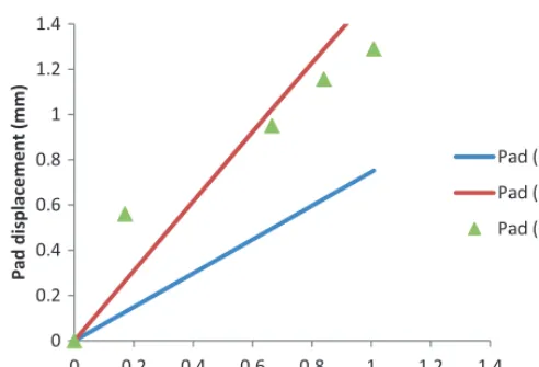
Fig.10showsthemeandatafromFig.6formeasuredpadandtip displacementsforthefourincrementsofpressure.Also,foreachof
thetipdisplacements,thecorrespondingpaddisplacementshave beencalculated,firstassumingthetorsionbarstoactmerelyas piv-ots(i.e.notorsionalstiffness)and,second,takingintoaccountthe stiffnessofthetorsionbars.Ascanbeseen,thesecondcalculation isreasonablyconsistentwiththemeasurementsindicatingthatthe analyticalmodelissufficientforthepurposesofsizingthetorsion bars.Afiniteelementmodeloftheplateincludingtheouterframe wasalsobuiltandthiswasloadedusingthemembranepressure
[image:5.646.88.487.56.414.2] [image:5.646.123.461.560.728.2]A.F.Aloglaetal./SensorsandActuatorsA236(2015)394–404 399 0 0.2 0.4 0.6 0.8 1 1.2 1.4
0 0.2 0.4 0.6 0.8 1 1.2 1.4
Pad dis pl ace m ent (m m)
Measuredpdisplacement(mm)
Pad(pivot)
Pad(calc.)
Pad(meas.)
[image:6.646.46.292.55.223.2]Fig.8.Analyticalmodelofcantileverforassessingpaddisplacmentcomparedwith
measuredvalues(Fig.4).
appliedoverthesurfaceofthepad,butsimulatedasapointforce atthecentreofthepad(Fig.9).Fig.10showstheresultingpadand tipdisplacementsforeachofthepressuresusedinthestatictests, alongsidecalculatedvaluesofthepaddisplacementforeachofthe simulatedtipdisplacementsusingEquation(1),showingthat,at thislimitedrangeofinputpressurestheelasticsimulationandthe elasticanalyticalmodelareinagreement.
Basedonthistentative verification,theanalyticalmodelcan nowbeusedtoassesstheinputforcecorrespondingtothe vari-ouspressureamplitudesseeninFig.4(c).However,Fig.4(c)shows
thatthemaximumtipdisplacementfortheunloadedcantilever
dependsonactuationfrequencyatleastupto50Hzabovewhich theactuatorisprobablylimitedbythesupplyofair.Thefrequency sensitivityisunlikelytobeduetoastructuralresonance(for exam-ple,thenaturalfrequencyoftheleaststiffpartofthesystem,the cantilever,isabout4kHz)norisitlikely,giventhedatainFig.6(a),
tobe due to membrane relaxation or leakage. Figs. 11 and 12
Fig.9. FEmodelofgripperplateforassessingpadandtipdisplacmentsforaforce
appliedatRP.
0 0.05 0.1 0.15 0.2 0.25 0.3 0.35
0 20 40 60 80
Pa d o r p disp la ceme nt (mm)
Membrane inputforce(mN)
Pad (sim.)
Tip (sim.)
Pad (calc.)
Fig.10.Simulatedpadandtipdisplacementsforpressureloadingofthepadat
valuesshowninFig.4.Solidlineshowscalculatedpaddisplacement(usingEquation
(1))foreachofthesimulatedtipdisplacements.
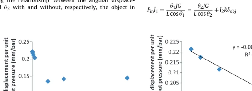
showthevariationofmaximumtipdisplacement(asvoltage out-putfromthephotodetector)withinputpressurepulseheightat theactuator(dataessentiallyre-plottedfromFig.4(b)).Thecurves arereasonablylinear(moresoatlowerfrequencies)andthusan overallcompliance(inmmtipdeflectionperbar) canbe deter-minedfortheactuator.ThisisplottedinFig.12forthewholerange
offrequency examined,andit canbeseenthat thecompliance
changeswithfrequencyovertherange0–50Hz,andlittle there-after.Thissuggeststhat thedynamic behaviourof theactuator is affectingthetipdisplacementand sothemostreliable mea-surementofthesystemcomplianceisgivenbyextrapolationto zerofrequency(Fig.12),i.e. avalueof0.223mm/bar.Sincethis is only around1% differenttothevalue measuredusing a
fre-quencyof1Hz,thepad and tipmeasurementsshown inFig.5
areunlikelytohavebeenmuchaffectedbytheactuatordynamic response.
Thecompliancecanfurtherbeusedtodeterminetheinputforce correspondingtoa giveninputpressurewhen theoutputforce,
Routput=0usingtherelationshipbetweeninputforceandcantilever
displacement:
Finput,Routput=0=
1 0.841tan
−1
0.223p3.15
(2)
wheretheinputpressure,p,isinbar.Whenthecantileverisloaded,
theforcesystembecomesstaticallyindeterminatewhichmakes
ananalyticalmodelabitmoretediousandso,forthepurposesof thispaper,theanalyticalrelationshipbetweentheinputpressure andinputforce(Equation(2))wasusedinalinearelasticFE sim-ulationofthegripperplatewithaloadedcantilevertocalculate theoutputforce.Theresultsofthissimulationarecomparedwith themeasuredoutputforcesat30sdwelltimefromthestatictests (Fig.6(b)),anditcanbeseenthatagreementisgooduptoa pres-sureof1bar,beyondwhichthesimulatedoutputforceishigher than thatmeasured, thediscrepancy increasingwithincreasing pressure.Thereasonforthiscanbeseeninthefiniteelement elas-ticstressdistributioncalculatedat1barinputpressureshownin
[image:6.646.314.562.58.218.2]y = 1.3664x
y = 1.4404x
y = 1.4718x
0 1 2 3 4 5 6 7 8
0 1 2 3 4 5 6
Ma ximum p dis p lace me nt (V)
Input pressurepulseheight(bar)
50Hz 100Hz
300Hz
y=2.25x
y=2.21x
y=2.15x
y=2.07x
0 2 4 6 8 10 12
0 1 2 3 4 5 6
Maxim um p di spla ce me nt (V)
Inputpressurepulseheight(bar)
1Hz 2Hz 4Hz 8Hz
(a)
(b)
Fig.11.(a)Effectoffrequencyonunloadedcantileversystemcomplianceathigherfrequencies(datafromFig.4),(b)effectoffrequencyonunloadedcantileversystem
complianceatlowerfrequencies(datafromFig.4).
thatthesimulationwouldbeinerrorintermsoftheinputaswellas intermsoftheresultingdeflections.Atanyrate,Equations(1)and
(2)canstillbeusedfordesignpurposessothatdimensionsofthe grippercanbechosentoavoidyieldusingverysimpleanalytical expressions(Fig.14).
Thenextstepforthisworkisfurtherdevelopmentofthe tac-tilesensingofmicro-objects.Extendingtheconsiderationsabove, andassumingnobending,thestaticstiffnessofagrippedlinear elasticobject,k,canbeobtained(forconceptualdesignpurposes)
by considering the relationship between the angular
displace-ments1 and 2 withand without,respectively, theobject in
place:
Withouttheobject:
l1cos1×Fin=1LJG
Withtheobjectgripped:
l1cos2×Fin=2JG
L +l2cos2×kıobj
So
Finl1= 1JG
Lcos1 =
2JG
Lcos2 +l2kıobj
y
= -0.0
025
x
+
0.22
R²
=
0.98
0.2
0.20
5
0.21
0.21
5
0.22
0.22
5
0
2
4
6
8
10
T
ip
displa
ceme
nt
pe
r
un
it
inpu
tp
re
ssu
re
(mm
/bar)
Input pressure pulse height (bar)
0.1
0.15
0.2
0.25
0
100
200
300
Ti
p
dis
pla
ce
me
nt
per
unit
inpu
tp
re
ssu
re
(m
m/b
a
r)
Actuaon fre
quency
(Hz)
(a)
(b)
[image:7.646.128.460.58.395.2] [image:7.646.94.498.438.731.2] [image:7.646.92.495.582.728.2]A.F.Aloglaetal./SensorsandActuatorsA236(2015)394–404 401
Fig.13.Elasticstressanalysisforloadedgripperplatewithappliedpressureof1bar.
[image:8.646.136.471.58.288.2] [image:8.646.140.467.311.725.2]Fig.15.Experimentalseutpforpick-and-placedemonstration.
or
k= JG
Lıobjl2
1
cos1 − 2
cos2
(3)
wherelistheperpendicular distancebetweenthecantilever
tip and torsion springs and L is the total length of the
tor-sion springs.Acknowledging the assumptions of its derivation,
Equation (3) couldbeused tomeasure thestatic stiffness of a grippedobjectprovidedthattheamountofitscompression(ıobj)
canbemeasuredandthattheangles1and2canbemeasured.
Equallythestiffnessofaviscoelasticobjectcouldbeassessedby recordingtheamplitudeofthecantilevertipwhilstgraspingan objectatdifferentfrequencies.
Oncethetechniquehasbeenvalidatedwithgrippedelasticand viscoelasticobjectsusingsimilarmeasurementstothesereported
here, the next stage is to develop a generic design approach
which allows the necessary measurements to be made at the
input side of the gripper where intervention is easier in real applications.
4. Devicedemonstration
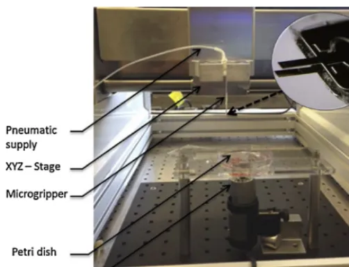
Afully-assembledversionofthedevicewasusedtodemonstrate theactuatorinpick-and-placemode,inairandunderwater.The
demonstrationconsistedofmanipulatingacidwashedzirconium
micro-beadsof200mdiameter (OPSDiagnostics,LebanonNJ,
USA),forwhichtheexemplardevicereportedabovewasmounted onanXYZstageandthemicro-beadsplacedinapetri-dishwitha monitoringcameraunderneath,asshowninFig.15.
Theabove-mentionedarrangementdemonstratedavery satis-factoryperformancebothinairandunderwater.Fig.16showsthe precisionofplacementthatcouldbeachievedusingtheproposed
manipulation technique, where 200mzirconium micro-beads
canbepreciselypositionedtoformeitheradottedarray(onthe left)orashapeofasmileyface(ontheright).
Fig.16. Variouspick-and-placearrangementsof200mzirconiummicro-beadsthatareachievablewiththisdesign.
[image:9.646.32.283.56.248.2] [image:9.646.103.483.370.551.2] [image:9.646.38.549.583.727.2]A.F.Aloglaetal./SensorsandActuatorsA236(2015)394–404 403
Onewayinwhichthestiffnessof grippedmicro-objectscan beassessedistovibratethecantileveratvariousfrequenciesand recordtheamplitudeofthedeflectionofthecantilever.Ifthisis doneforthegripperinairandsubsequentlywiththeobjectgripped, thequotientofthesedeflectionsdeterminesthestiffnessofthe object:
AR=Aobj Aair
(4)
Thisprocedurewascarriedoutwitha1baractuatorpressure, gripping400mhydrogelbeadsandusingfrequenciesof1Hz(A1), 2Hz(A2),4Hz(A3)and10Hz(A4).Theresults,showninFig.17
clearlyindicatethatthereisareductionintipamplitudeforthe grippedbeadateachfrequency.Theresultsfurthershowthatthe amplitudechangeisdifferentateachfrequencyand,furthermore, thattherearechangesinamplitudewithtimeatagivenfrequency. Thisisprobablyduetoacombinationofdynamiceffectswithin theactuator-membranesystem,aswellasintheresponseofthe hydrogelbead.Thesemattersarenotpursuedinthecurrentpaper, butwillinformfutureworkusingdevicesofthistype.
5. Conclusions
This work demonstrates a pneumatically actuated
micro-gripperthathastheabilitytopickandplacemicron-sizedobjects
with the potential to provide tactile feedback. The pneumatic
micro-actuatorcanhaveitspressure-forcerelationshipmeasured andcontrolledinbothstaticanddynamicmodeswithasimpleset up.Thetwostainlesssteelgripperarmscanbefabricatedusing low-cost,scalablephoto-etchingmanufacturingtechniquewitha rangeofdimensions,allowingthisdesign tobescaledtofitthe chosenapplication.Asthephoto-etchingmanufacturingisa photo-lithographytechniquewithhighprecision,itispossibletofabricate stainlesssteelbasedgripperwithdimensionssmallerthan100m forsinglecellmanipulation.Thestiffnessofthetwotorsionbars canaidintailoringtheuseofthegripperwiththebarsbehaving almostasapivotorusedtodown-regulatetheinputforce(formore delicatetasks).Besidescontrolling theinputand outputforces, thedesignofthegripperarmscanbetunedinordertoprovide adeflectionofthearms,whosemeasurementcanbeusedto mea-surethegrippingforceinoperationandcanpotentiallybefedback tocontroltheforceorusedtoassessthegrippedobject.Besides thepotentialuseofgripperformanipulatingembryosforcloning
applications,themechanicalmicro-tweezersmayprovideanew
waytopick-and-placecellaggregatesforbiofabricatingsynthetic tissues[25,26].Futureworkwillfocusonfurtherminiaturizationof thegripperformanipulatingsmallerobjects(e.g.singlecells)and treatmentofthegrippersurfacetoovercomepotentialstriction issues.Furtherimprovementofthegripper’stactilesensingmay alsoleadtomechanicalassessmentofbiologicaltissuesinvivo.
Acknowledgements
ThisresearchworkissupportedbytheEngineeringandPhysical SciencesResearchCouncil(EPSRC)(GrantCode:EP/I019472/1).A. AloglaisgratefultotheSaudiGovernmentforaPhDscholarship. C.BalmerandP.ScanlanaregratefultoEPSRCforPhDscholarship funding.
References
[1]M.L.Juan,M.Righini,R.Quidant,Plasmonnano-opticaltweezers,Nature Pho-ton.5(6)(2011)349–356.
[2]X.Wang,etal.,Enhancedcellsortingandmanipulationwithcombined opti-cal tweezerand microfluidic chiptechnologies, LabChip 11(21) (2011) 3656–3662.
[3]H.Zhang,K.-K.Liu,Opticaltweezersforsinglecells,J.R.Soc.Interf.5(24)(2008) 671–690.
[4]A.Ashkin,etal.,Observationofasingle-beamgradientforceopticaltrapfor dielectricparticles,Opt.Lett.11(5)(1986)288–290.
[5]C.Piggee,Opticaltweezers:notjustforphysicistsanymore,Anal.Chem.81(1) (2008)16–19.
[6]K.König,etal.,Celldamageinnear-infraredmultimodeopticaltrapsasaresult ofmultiphotonabsorption,Opt.Lett.21(14)(1996)1090–1092.
[7]H.-Y.Chan,W.J.Li.Athermallyactuatedpolymermicroroboticgripperfor
manipulationofbiologicalcells.ProceedingsICRA’03,IEEEInternational
Con-ferenceonRoboticsandAutomation,Taipei,Taiwan,1,pp.288–293.
[8]M.Zeman,G.Knopf,Design,kinematicmodelingandperformancetestingof anelectro-thermallydrivenmicrogripperformicromanipulationapplications, J.Micromech.Microeng.16(2006)1540–1549.
[9]S.A.Bazaz,F.Khan,R.I.Shakoor,Design,simulationandtestingofelectrostatic SOIMUMPsbasedmicrogripperintegratedwithcapacitivecontactsensor, Sens.ActuatorsA:Phys.167(1)(2011)44–53.
[10]J.Ok,Y.W.Lu,C.J.Kim,Pneumaticallydrivenmicrocageformicrobe manipula-tioninabiologicalliquidenvironment,J.Microelectromech.Syst.15(6)(2006) 1499–1505.
[11]R.Velazquez,etal.,Alow-costhighly-portabletactiledisplaybasedonshape memoryalloy micro-actuators,in:ProceedingsVECIMSIEEEInternational ConferenceonVirtualEnvironments,Human-ComputerInterfacesand Mea-surementSystems,GradiniNaxos,Italy,2005,pp.121–126.
[12]J. Agnus,N.Chaillet, Overview of microgrippersand designof a micro-manipulation station based on a MMOC microgripper, in: Proceedings ComputationalIntelligenceinRoboticsandAutomation,Finland,2005,pp. 117–123.
[13]A.Menciassi,etal.Aworkstationformanipulationofmicroobjects.Proceedings
ICAR’97,8thIEEEInternationalConferenceonAdvancedRobotics,Monterey,
CA,pp.253–258.
[14]G. Reyne, Electromagnetic actuation for MOEMS, examples, advantages and drawbacks of MAGMAS, J. Magnet. Magnet. Mater. 242 (2002) 1119–1125.
[15]M.DeVolder,Pneumaticandhydraulicmicroactuators:areview,J.Micromech. Microeng.20(043001)(2010)18pp.
[16]S.Bütefisch,V.Seidemann,S.Büttgenbach,Novelmicro-pneumaticactuator forMEMS,Sens.ActuatorsA:Phys.97(2002)638–645.
[17]A.J.Moers,M.F.DeVolder,D.Reynaerts,Integratedhighpressure microhy-draulicactuationandcontrolforsurgicalinstruments,Biomed.Microdev.14 (4)(2012)699–708.
[18]K.Takemura,S.Yokota,K.Edamura,Developmentandcontrolofamicro arti-ficialmusclecellusingelectro-conjugatefluid,Sens.ActuatorsA:Phys.133(2) (2007)493–499.
[19]K.Shimizu,A.Shunori,K.Morimoto,M.Hashida,S.Konishi,Developmentofa biochipwithseriallyconnectedpneumaticballoonsforcell-stretchingculture, Sens.ActuatorsB:Chem.156(1)(2011)486–493.
[20]H.W.Kang, I.H.Lee,D.W.Cho,Developmentofa micro-bellowsactuator usingmicro-stereolithographytechnology,Microelectron.Eng.83(4)(2006) 1201–1204.
[21]A.Alogla,etal.,Ascalablesyringe-actuatedmicrogripperforbiological manip-ulation,Sens.ActuatorsA:Phys.202(2013)135–139.
[22]M.KersaudyKerhoas,F.Amalou,A.Che,J.Kelly,Y.Liu,M.P.Y.Desmulliez,W. Shu,Validationofafullyintegratedplatformanddisposablemicrofluidicchips enablingparallelpurificationofgenomesegmentsforassembly,Biotechnol. Bioeng.111(8)(2014)1627–1637.
[23]M.Milad,etal.,TheeffectofcoldworkonstructureandpropertiesofAISI304 stainlesssteel,J.Mater.Process.Technol.203(1)(2008)80–85.
[24]W.Shu,E.D.Laue,A.A.Seshia,Investigationofbiotin–streptavidinbinding interactionsusingmicrocantileversensors,Biosens.Bioelectron.22(2007) 2003–2009.
[25]A.N.Mehesz,J.Brown,Z.Hajdu,W.Beaver,J.V.L.daSilva,R.P.Visconti,V. Mironov,Scalableroboticbiofabricationoftissuespheroids,Biofabrication3 (2)(2011)025002.
[26]A.Faulkner-Jones,S.Greenhough,J.A.King,J.Gardner,A.Courtney,W.Shu, Developmentofavalve-basedcellprinterfortheformationofhuman embry-onicstemcellspheroidaggregates,Biofabrication5(1)(2013)015013. Biographies
AgeelAloglareceivedhisB.Eng.inMechanicalEngineeringfromtheKingFahad
UniversityofPetroleumandMinerals,KingdomofSaudiArabiain2002,andaPh.D.
degreefromtheuniversityofHeriot-Watton2014.HeiscurrentlyanAssistant
ProfessorintheSchoolofEngineeringatTaifUniversity,KingdomofSaudiArabia.
Hisresearchinterestsarefocusedonmicrosystemsandmechanicalgrippers.
FaridAmaloureceivedhisPh.D.inMicroEngineeringandMicroMagnetismatthe
SwissFederalInstituteofTechnologyinLausanne(EPFL)in2003.Followinghis
postdoctoralpositionsatHeriot-WattUniversityandSouthamptonUniversity,heis
currentlyanAssistantProfessorinPhysicsatAlfaisalUniversity,KingdomofSaudi
Arabia.
ChrisBalmergraduatedwithanM.Eng.degreeinMechanicalEngineeringfrom
Heriot-WattUniversity,Edinburghin2014.HeiscurrentlyworkingonhisPh.D.on
researchinterestsarefocusedonmicrogrippersandtactilefeedbackforbiological tissues.
PaulScanlangraduatedwithaB.Eng.degreeinRoboticsandCybertronicsfrom
HeriotWattUniversity,Edinburghin2011.HeiscurrentlystudyingforhisPh.D.in
theMechanicalProbingofHumanTissue.Hisresearchinterestsinclude
microfab-ricationtechniquesandengineeringforbiomedicalapplications.
WenmiaoShureceivedhisB.Eng.degreeinPolymerMaterialsfromtheDalian
Uni-versityofTechnology,China,in1998,andaPh.D.degreefromtheUniversityof
Cambridgein2006.HeiscurrentlyReaderofMicroengineeringintheSchoolof
EngineeringandPhysicalSciencesatHeriot-WattUniversity.Hisresearchinterests
coverarangeofbiomedicalmicroengineeringtopicsincludingmicromechanical
sensorsandactuators,biosensors,lab-on-a-chipsystemsand3Dbiofabrication.
RobertL.ReubenisaProfessorofMaterialsEngineeringintheSchoolof
Engineer-ingandPhysicalSciencesatHeriot-WattUniversity.HegraduatedwithaFirstClass
HonoursinMetallurgyfromtheUniversityofStrathclydein1974,afterwhichhe
workedwiththeUnitedKingdomAtomicEnergyAuthority.In1977hejoinedthe
OpenUniversity’sOxfordResearchUnitresearchingthepermeation
characteris-ticstohydrogenanditsisotopesofcandidatefusionreactorcontainmentmaterials,
gainingaPh.D.inthatareain1980.Hisresearchfieldincludesexperimental
mechan-icsandmicrosystemsengineering(oftenformedicalapplications),andsensor-based