Manipulation of the spatial distribution of laser-accelerated proton beams
by varying the laser intensity distribution
B.Aurand,1,2,a)L.Senje,1K.Svensson,1M.Hansson,1A.Higginson,3A.Gonoskov,4 M.Marklund,4A.Persson,1O.Lundh,1D.Neely,5P.McKenna,3and C.-G.Wahlstr€om1 1
Department of Physics, Lund University, P.O. Box 118, 22100 Lund, Sweden 2
Institut f€ur Laser- und Plasmaphysik, Heinrich-Heine Universitat, 40225 D€ €usseldorf, Germany 3
SUPA Department of Physics, University of Strathclyde, Glasgow G4 0NG, United Kingdom 4
Department of Applied Physics, Chalmers University of Technology, 41296 Gothenburg, Sweden 5
Central Laser Facility, STFC, Rutherford Appleton Laboratory, OX11 0QX Didcot, United Kingdom
(Received 25 October 2015; accepted 20 January 2016; published online 18 February 2016)
We report on a study of the spatial profile of proton beams produced through target normal sheath acceleration using flat target foils and changing the laser intensity distribution on the target front surface. This is done by either defocusing a single laser pulse or by using a split-pulse setup and irra-diating the target with two identical laser pulses with variable spatial separation. The resulting proton beam profile and the energy spectrum are recorded as functions of the focal spot size of the single laser pulse and of the separation between the two pulses. A shaping of the resulting proton beam pro-file, related to both an increase in flux of low-energy protons in the target normal direction and a decrease in their divergence, in one or two dimensions, is observed. The results are explained by sim-ple modelling of rear surface sheath field expansion, ionization, and projection of the resulting proton beam.VC 2016 Author(s). All article content, except where otherwise noted, is licensed under a
Creative Commons Attribution (CC BY) license (http://creativecommons.org/licenses/by/4.0/). [http://dx.doi.org/10.1063/1.4942032]
I. INTRODUCTION
More than a decade ago, first experimental results1,2 showed the possibility to accelerate protons to tens of MeV kinetic energy over a sub-mm length by using ultra-intense laser pulses irradiating the front side oflm-thick metal foils. The laser pulse forms a megaampere electron current inside the target penetrating through the rear surface and expanding into vacuum, leading to a charge separation on the scale of the Debye length. In the resulting electric field—which is of the order of up to a few TV/m—protons, mainly from the hydrocarbon contamination layer on the target rear surface, are quickly accelerated to high energies.3,4
This process, the target-normal-sheath-acceleration (TNSA) mechanism,5 creates a continuous, Boltzmann-like, energy distribution up to a cut-off energy, which has attracted consid-erable interest, partly from a fundamental plasma physics point of view and partly because of its great potential for novel appli-cations. It represents a very compact source of energetic ions. The pulse duration, at the source, is short, and the transverse emittance is very low.6–8 Potential applications in medi-cine, material science, accelerator physics, and industry, for example, have been widely discussed.3,9However, in order to become a useful source for applications, a number of pa-rameters must be greatly improved. For example, the shot-to-shot stability, the maximum proton energies, and the laser-to-proton energy conversion efficiencies must be increased. At the same time, the beam divergence should be reduced. In addition, for many applications, the proton energy distributions must be reduced, and ideally, a narrow
energy spread achieved. All these improvements require further experimental and theoretical studies and enhanced understanding of the fundamental processes involved.
In typical TNSA experiments, using a flat metallic target foil irradiated on the front surface by a tightly focused laser pulse, the beam of protons leaves the target’s rear surface centred along the target’s normal (TN) direction. The maxi-mum proton energy, EProt, within the beam depends on the
peak laser intensityILand, thus, for a given laser pulse
dura-tion, both on the pulse energy and the irradiated spot size on the target. Brenner et al.10 show that increasing IL by
increasing the pulse energy has a significantly larger influ-ence on the total flux of protons than the same increase in in-tensity obtained by reducing the laser spot size. Xu et al.11
and Greenet al.12show that, with constant laser pulse energy and pulse duration, the total flux of protons can be increased by defocusing the laser at the target, even though the peak laser intensity is decreased. The proton beam divergence depends on the laser parameters and on the proton energies; the most energetic protons exhibit the smallest divergence.13 Schollmeier et al.14 used micro-structured target foils as a tool to demonstrate the effect of defocusing the laser beam on the generated proton beam. Several more studies have been reported in the literature regarding the proton beam divergence and laminarity15 and how they can be manipu-lated, e.g., via the use of curved targets.16,17In this paper, we report on experimental studies of how the angular/spatial dis-tribution of the proton beams can be manipulated without changing the target shape or composition, and instead by varying spatially the laser intensity distribution on the tar-get’s front surface. We keep the target and laser parameters fixed and vary the intensity distribution while monitoring the a)
Electronic mail: [email protected]
spatial proton beam profile. In recent studies, it was shown that by using a fixed, hollow, doughnut-like laser beam pro-file, the beam divergence, and energy profile could be manip-ulated.18 Here, we vary the intensity distribution either by defocusing the laser on the target or by dividing the focused laser pulse into two spatially separated pulses, with a separa-tion that can be continuously varied. In the first case, we find that the proton beam divergence can be significantly reduced by optimally defocusing the laser pulse, and in the second case that, with optimized separation between the two foci, the proton beam divergence is reduced in the direction of the separation of the foci, resulting in an elliptically shaped pro-ton beam. These collimation effects, in one or two dimen-sions, are found to be mainly affecting the relatively large number of low energy protons. The number of low energy protons in the target’s normal direction increases while their divergence decreases, resulting in intense beams of low-energy protons, collimated in one or two dimensions.
II. EXPERIMENTAL SETUP AND METHODS
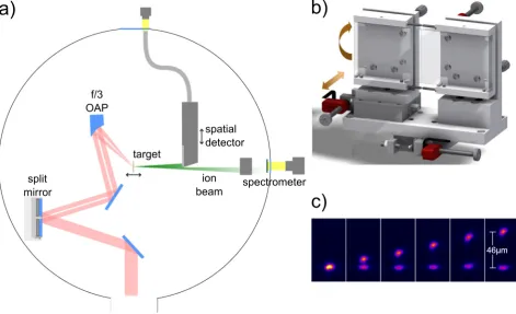
The experiments were carried out using the Lund 10 Hz multi-terawatt laser system; a chirped-pulse amplification (CPA) based Ti:sapphire laser with a pulse duration of 35 fs and a temporal contrast better than 110950 ps before the main pulse. In the experiments presented here, the energy per pulse, on target, was kept fixed at 0.6 J. The experimental setup19is shown in Fig.1(a). After compression, the 45 mm di-ameter beam was guided into the interaction chamber and sent onto a split-mirror setup (Figure1(b)) before reaching an
off-axis parabolic (OAP) focusing mirror. For the first part of the investigation, the split-mirror setup was positioned in a way that the full laser beam was reflected on one of the mirrors, and thus, only one focal spot was produced. Instead, the target foil was moved to different positions along the optical axis around the beam waist. For the second part of the investiga-tion, the split-mirror setup was positioned such that each laser pulse was divided into two halves, resulting in two identical focused laser pulses hitting the target foil. The foil was then positioned in the focal plane of the focusing mirror while the separation between the two foci was varied between shots.
The split-mirror setup consists of two planes, protected sil-ver mirrors of standard optical quality (k/10 flatness). They have a vertically oriented wedged shaped edge in order to ena-ble the mirrors to be mounted very close to each other, with a gap of only a few tenths of a millimetre, but with the possibility to move freely relative to each other. Due to a separate mount-ing, the mirrors can be tilted independently in vertical and hori-zontal directions. In addition, one of the mirrors is mounted on a linear translation stage, which moves the mirror perpendicu-lar to its surface, enabling the relative optical path length and therefore the relative timing of the pulses to be accurately con-trolled. The complete split-mirror setup is further mounted on another linear translation stage moving it transversely with respect to the laser beam. This enables the split ratio of the pulses to be varied. Both beams are sent onto the same off-axis parabolic mirror, with 152 mm focal length and focused to a circular spot with radiusrL¼2.5lm (HWHM) reaching a peak
intensity ofIL¼21019W/cm2.
[image:2.607.67.539.429.716.2]Applying angular tilts in one direction to one of the mir-rors, the two foci can be separated in that direction of the focal plane (Figure1(c)). Note that this tilt is induced more than 1 m upstream of the interaction point and is in the order of somel-rad. Neither a significant pulse front tilt nor a sig-nificant relative temporal difference between the beams is induced. By use of a deformable mirror in the beam line, the phase was corrected to ensure a good quality of the focus in the overlapped case. The slight horizontal elongation of the beam, which can be seen in Figure 1(c), is independent of the tilt direction. Fine adjustment of the temporal overlap can be done by adjustments of the relative path length while monitoring the interference patterns occurring in the focal plane when the foci have a spatial overlap. In the studies reported here, the splitting ratio was fixed at either 100:0 or 50:50, and the relative time delayDt¼0.
As a target, we used 3lm-thick Al foils mounted in a matrix target holder realizing 340 independent targets and where each new target can be aligned within a few seconds, with an accuracy of better than 18lm (standard deviation) with respect to the laser focus position. The target is mounted at 45, horizontally tilted, with respect to the laser axis.
In order to take advantage of the high repetition rate of the laser and the fast target alignment procedure, only online proton diagnostics were used. A magnetic-field based proton spectrometer disperses the protons, after passing through a 1 mm entrance pinhole, depending on their energy onto a scintillator (St. Gobain: BC-408; 500lm thick), wrapped in
a 12lm thick aluminum foil to block heavy ions, which is
monitored by a 16-bit camera (Princeton: PhotonMAX1024). The proton signal is collected in the target’s normal direction covering a solid angle of 8105sr, and the energy uncer-tainty due to the pinhole size isDE/E10%. In addition, a spatial detector is used to monitor the spatial-intensity distri-bution of the proton beam.20A scintillator (St. Gobain: BC-408; 500lm thick) is positioned (6562) mm behind the tar-get in a light shielded box with a 12lm thick and light tight Al entrance window. The scintillator emission is imaged onto an optical fibre bundle, which allows for the image to be transferred onto a 12-bit CCD camera placed outside the vacuum chamber. This enables a reconstruction of the two-dimensional proton beam spatial profile. With this detector
setup, the signal is not energy selective, but represents a superposition of all protons, which are stopped in the scintil-lator (0.9 MeV<EStop<7 MeV). We typically investigate
protons with maximum kinetic energies of E6 MeV, so most protons are stopped in the scintillator. The signal from the detector is thus not representing the number of protons, but rather the deposited energy. By adding additional bars of aluminum with different thicknesses in front of the detector allowed us to distinguish between electrons and protons in the detector, which was used to calibrate the device.
III. EXPERIMENTAL RESULTS
A. Defocus scan with a single laser focus
When we use only one laser focus and move the target foil along the laser propagation axis, i.e., through the focus, we find, as expected, that the highest proton energy is obtained with the target at best focus (r0lm2.5lm), where the peak
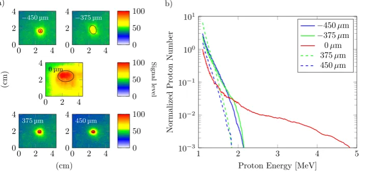
intensity is the highest. The proton beam is then centered along the TN direction, and the profile, integrating over all protons with E>0.9 MeV, is spatially round and smooth. However, the divergence dramatically decreases when the target foil is positioned at 6375lm (r375lm8.5lm) or at 6450lm
(r450lm10.5lm) from best focus (see Figure2(a)). This
cor-responds to approximately three to four Rayleigh lengths, and the peak laser intensity is reduced by roughly one order of magnitude. The laser beam profile was carefully investigated in order to ensure a homogeneous distribution of energy over the enlarged irradiated spot. The small difference in the inten-sity of the proton beam distribution. which can be seen in Figure2(a)for target positions before and behind the focus, is not systematically different for the full measurement cam-paign, but they differ systematically within one measurement run with the same laser alignment. This might result mainly from the fact that a laser beam profile for a real laser is not only perfectly Gaussian but also to a smaller extent that a real focussing element is not perfectly parabolic. In this case, it can be shown by ray-tracing that there are small differences in local divergence and intensities on small scales within the beam profile.
The observed decrease in the proton beam divergence is not due to the decrease in the laser intensity, which is easily verified by reducing the laser energy with the target at a best
[image:3.607.51.419.595.766.2]focus. Instead, it represents a significant relative increase in the number of low energy protons propagating close to the TN direction. The overall lower proton energy results from the de-focusing and therefore the reduced sheath field strength.
Figure 2(b) shows the proton energy distribution observed in the TN direction with the target both at the best focus and defocused by 375lm. This shows the significant relative increase in the number of low energy protons and a corresponding decrease in protons with the highest energies. This resembles the finding in Ref.11, but here, it is evident that the increase in low-energy protons in the TN direction is partly due to a reduction in divergence of these protons. Defocusing the laser pulse thus leads to reduced divergence and a significantly increased relative flux of low energy pro-tons in the centre of the beam, even though the maximum proton energy is reduced. Using different aluminum filters in front of the spatial detector reveals as well the finding that in the defocused case, the energy of the protons in the center of the beam decreases, while their particle number increases.
B. Two foci of equal intensity and variable separation with the target foil at the best focus
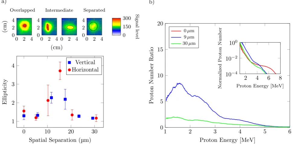
Using similar measurement methods compared to the previous paragraph, we find as expected that the highest pro-ton energy is obtained with zero separation, i.e., when the two foci overlap and give rise to the highest peak intensity on target. The spatial beam profile is then round in the TN direction, and with the highest energy protons having the smallest divergence, consistent with several previous reports.2,21,22When separating the two foci in one direction,
we find that the proton beam shape changes from circular to elliptical, with the minor axis in the direction of separation. When the separation is increased further, the proton beam profile becomes round again (see Figure 3(a)). Since this effect occurs both for horizontal and vertical tilt, it is con-cluded that it is not due to the incidence angle between the laser and target, e.g., caused by an elongated beam profile due to the projection on the target surface. The degree of el-lipticity, defined as the ratio between the major and the minor axis of an ellipse fitted to 80% level in each proton dose distribution, is shown in Figure3(a)for different sepa-ration of the foci. When placing a filter in front of the spatial detector, stopping protons with energy below 1.7 MeV, we find that the elliptical shape disappears and we are left with a significantly weaker but circular proton beam, for all values of foci separation.
This observation is similar to the case of defocusing as discussed above, where we observed a collimation in two dimensions of low energy protons when defocusing the laser on the target foil. Here, we also find a collimation of low energy protons, but now only in one direction. This is further verified by measuring the proton energy distribution in the TN direction, as a function of separation between the two foci. Figure3(b)shows two plots of the proton energy distri-bution in the TN direction with the two foci separated at
9lm and 30lm divided by the distribution obtained with the
two overlapping foci. The inset shows the original signal. These plots show the significant increase in the number of low energy protons obtained with the optimum separation, accompanied by a relative decrease in protons with the high-est energies. With large separation (30lm) between the two foci, two independent proton sources are obtained, with the
[image:4.607.61.547.459.697.2]same reduction in the maximum energy as for the optimum separation, but without the enhancement in proton flux at low energies. These graphs show that the elliptical shape observed with the spatial detector actually represents a collimation effect, with an increase in proton number in TN direction, and that this collimation mainly affects the low energy protons.
IV. MODELLING
A numerical model was developed to investigate how the size of the laser focus and the separation of the laser foci in the case of two beams may be expected to influence the resulting proton beam distribution. The model (an earlier version of which is described in Ref.23) calculates how the evolving fast electron density distribution on a grid corre-sponding to the target rear surface maps into the beam of protons accelerated by TNSA. Fast electrons produced at the target front side in a given laser focus are assumed to be bal-listically transported through the target in a beam with a fixed divergence angle. Transport phenomena such as colli-sions and self-generated fields are not accounted for, but are expected to have a limited effect in relatively thin targets.24 Recirculation or refluxing of fast electrons within the foil is also neglected. It was validated in simulations that refluxing for a 35 fs-duration laser pulse will occur essentially only for target thicknesses of more than 3lm. The rear-surface fast electron sheath dynamics, field-ionization of hydrogen, and the direction of projection of the resulting protons are calcu-lated. Unlike more computationally intensive 3D Particle-in-Cell (PIC) modelling, this simpler approach enables a range of parametric scans to be performed relatively quickly, to explore the expected changes to the proton beam profile.
The initial diameter of the fast electron distribution at the target rear side, arising from a laser focal spot of radiusrLat
the front side, is given byde¼2ðrLþDtanh1=2Þ, whereh1=2
is the divergence half-angle of the electron beam as it propa-gates within the target of thicknessD. The sheath profile due to the single laser focus is assumed to be parabolic.24In the case of two laser foci, two fast electron distributions are gen-erated at the target rear, with the degree of overlap depending on the separation of the laser foci and the magnitude ofh1=2.
In the calculations below, D¼3lm and h1=2 is set to 30.
The target rear surface is defined as a spatial grid of 8080 cells of 0.025lm size, centred atX¼Y¼0. Electrons arrive over the duration of the laser pulse, which is set equal to 35 fs. The magnitude of the sheath field increases with the increase in the fast electron number density over the first half (rising edge) of the laser pulse and thereafter decreases with time due to lateral expansion of the electron population. The maxi-mum field strength is calculated (assuming a sharp boundary) as Emax¼E0
ffiffiffiffiffiffiffiffiffiffi 2=eN
p
, where eN is Euler’s number (2.7183),
E0 ¼
ffiffiffiffiffiffiffiffiffiffiffiffiffiffiffiffiffiffiffiffiffi
ne0kBTe=0 p
,0is the vacuum permittivity, andTeand
ne0 are the fast electron temperature and maximum density,
respectively (as derived in Ref.25). The fast electron temper-ature is determined from ponderomotive scaling.26The num-ber of fast electrons generated, and thus the fast electron density, is calculated assuming a laser pulse energy of 0.6 J and a laser-to-fast electron energy conversion efficiency of 20%. The conversion efficiency is fixed at this value in the
intensity range explored in this study, based on measurements reported in Ref. 27. The initial transverse sheath expansion velocity is set equal to 0.7c (as determined from a previous experiment8and simulations28), and it decreases exponentially with a 1/e time constant of 60 fs. The rate of reduction in the transverse expansion velocity is based on time- and space-resolved interferometry measurements of a probe beam reported in Ref.8, scaled to the shorter laser pulse used in the present work. The sheath evolution is calculated in 0.8 fs steps.
Free protons are released by field ionization of a uniform layer of hydrogen, as calculated using the Ammosov-Delon-Krainov (ADK) rate29at each time step. Changes in the pro-ton front due to the evolving electric field are calculated, and the local gradient to this front is used to determine the pro-jection of the resulting beam of protons. The detector plane is defined by a 3 cm3 cm spatial grid with a resolution equal to 100lm and is set 6.5 cm from target, to match the experimental conditions. The 2D proton beam spatial-intensity distributions calculated after 200 fs are compared with the measurements.
A. Defocusing
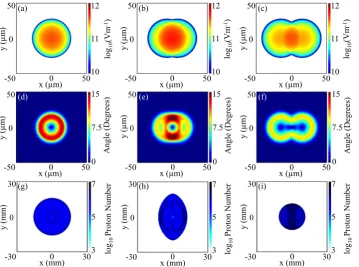
The simulations show that as the laser pulse is defocused, the maximum kinetic energy in the proton beam is reduced, but the number of low-energy protons increases. In addition, more gradual gradients in the sheath field lead to a reduction in the beam divergence. The result is therefore, at the optimum amount of defocusing, a narrow and intense beam of low energy protons. This is illustrated in Figure4. Further defocus-ing reduces the laser intensity too much, and the proton beam quickly reduces in brightness. In the simulation, the proton dis-tribution can be analyzed separately for different proton ener-gies. When this is done, it is found that the observed intense and narrow beam is due to protons with kinetic energy less than 70% of the maximum energy obtained at best focus. This is in agreement with the experimental finding.
B. Two spatially separated foci
due to protons with kinetic energy less than 70% of the max-imum energy. Analyzing only the high energy range of the proton energy distribution, circular beam profiles are found independently of spot separation. This is also in agreement with the experimental findings.
V. CONCLUSION
This article addresses the influence of defocusing and focus shaping of the laser pulse on the generated proton beam profile and the proton energy distribution. Defocusing a single laser beam by a few Rayleigh lengths on the target front sur-face results in a spatially larger electron distribution directed towards the target rear surface, which has a lower average energy due to the lower initial laser intensity. As a result, the created sheath field on the rear surface covers a larger area, resulting in a larger proton source size, but is weaker than in the case of a focused laser beam. The secondary accelerated beam of protons is more collimated, due to the larger electron
distribution at the target rear side leading to a lesser electro-static sheath field gradient, and therefore more directed elec-tric field distribution. At the same time, the proton flux is increased due to the larger source size of protons being accel-erated. This however results in a reduction of the electric field strength, leading to an overall lower proton energy.
[image:6.607.49.402.56.236.2]By using two laser beams, to create two foci separated by a few laser spot diameters, we could transfer this effect of beam-shaping to a tool in order to generate a customized proton beam of high flux in one direction. In that case, the superposition of the shape of the two foci as well as the resulting electron distribution driven through the target forms an expanded sheath field in one direction at the target rear surface. The beam of accelerated protons is produced with a lower divergence in only one direction. We demon-strated that for our experimental parameters, this effect occurs for a focal spot separation between the two foci of approximately three focal spot diameters. A larger beam sep-aration results in two independent proton sources,30 each FIG. 4. Simulation results showing the electrostatic sheath field distribution after 200 fs for: (a) rL¼5lm, (b) rL¼10lm, and (c) rL¼15lm. The corresponding proton beam profiles, integrated over the full proton energy range, are shown in (d)–(f), respec-tively. In the defocused case, the sheath field is larger and weaker, resulting in a proton beam with smaller divergence.
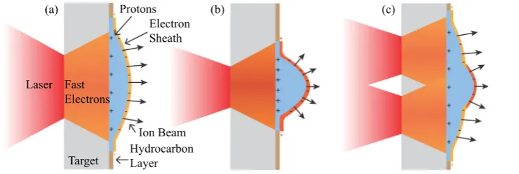
[image:6.607.50.410.494.761.2]with high divergence but relative low energy. A smaller sep-aration results in one proton source with high divergence and high energy, due to the addition of both laser beams. Figure 6 illustrates schematically the sheath expansion in three of the cases investigated experimentally. These results obtained by laser beam splitting presents an indirect mea-surement of the sheath field size, which was estimated to be in the order of 20lm. This is in agreement with the results obtained in Ref.31using a laser system with a similar pulse duration as in our study, i.e., a few tens of femtoseconds. For longer laser pulse durations, where the electrons can be accelerated and recirculated within the target during the pulse duration, the sheath field becomes larger, as, e.g., obtained in Refs.32and33.
In summary, the proton beam can be shaped by this effect, increasing the proton flux for the low energy proton part. The cost of this effect is a reduction in the maximum proton energy. For distinct applications which do not need high proton energies but a high proton flux with a shaped beam profile (e.g., proton beam writing34 or radioisotope production35), this method might be sufficient to at least pre-form the beam profile before using collimators to create the desired shape. This enhances the process efficiency and reduces the number of protons which need to be dumped away creating unnecessary activation or radiation at the col-limator. Using this technique on high energy lasers could be a scheme to accelerate protons as a fast ignition driver. Here, as well primarily a high proton flux is needed.
In the case studied above, both laser beams interact with the target at the same time. In further studies, one can intro-duce a temporal delay between the two pulses, which may result not only in a collimation but also in a change of direc-tion of the proton beam due to a possible tilt of the sheath field front at the target rear surface. This may allow for a new method of combined beam collimation and shaping. Exploring the influence of varying the relative intensities of the two pulses is additional options for further studies.
ACKNOWLEDGMENTS
We gratefully thank the Knut and Alice Wallenberg Foundation, including their funding of the PLIONA project, the Swedish Research Council, and the Swedish Foundation for Strategic Research for financial support. We also acknowledge support from EPSRC (Grant No. EP/ J003832/1) and Laserlab-Europe/CHARPAC (Grant Agreement No. 284464).
1E. L. Clark, K. Krushelnick, J. R. Davies, M. Zepf, M. Tatarakis, F. N. Beg, A. Machacek, P. A. Norreys, M. I. K. Santala, I. Watts, and A. E. Dangor,Phys. Rev. Lett.84, 670 (2000).
2
R. A. Snavely, M. H. Key, S. P. Hatchett, T. E. Cowan, M. Roth, T. W. Phillips, M. A. Stoyer, E. A. Henry, T. C. Sangster, M. S. Singh, S. C. Wilks, A. MacKinnon, A. Offenberger, D. M. Pennington, K. Yasuike, A. B. Langdon, B. F. Lasinski, J. Johnson, M. D. Perry, and E. M. Campbell,
Phys. Rev. Lett.85, 2945 (2000). 3
H. Daido, M. Nishiuchi, and A. S. Prizhkov,Rep. Prog. Phys.75, 056401 (2012).
4M. Passoni, L. Bertagna, and A. Zani,New J. Phys.
12, 045012 (2010). 5
S. C. Wilks, A. B. Langdon, T. E. Cowan, M. Roth, M. Singh, S. Hatchett, M. H. Key, D. Pennington, A. MacKinnon, and R. A. Snavely, Phys. Plasmas8, 542 (2001).
6
J. Fuchs, P. Antici, E. d’Humilres, E. Lefebvre, M. Borghesi, E. Brambrink, C. A. Cecchetti, M. Kaluza, V. Malka, M. Manclossi, S. Meyroneinc, P. Mora, J. Schreiber, T. Toncian, H. Pepinm, and P. Audebert,Nat. Phys.2, 48 (2006).
7
J. Fuchs, C. A. Cecchetti, M. Borghesi, T. Grismayer, E. d’Humilres, P. Antici, S. Atzeni, P. Mora, A. Pipahl, L. Romagnani, A. Schiavi, Y. Sentoku, T. Toncian, P. Audebert, and O. Willi,Phys. Rev. Lett.99, 015002 (2007). 8
S. Buffechoux, J. Psikal, M. Nakatsutsumi, L. Romagnani, A. Andreev, K. Zeil, M. Amin, P. Antici, T. Burris-Mog, A. Compant-La-Fontaine, E. d’Humieres, S. Fourmaux, S. Gaillard, F. Gobet, F. Hannachi, S. Kraft, A. Mancic, C. Plaisir, G. Sarri, M. Tarisien, T. Toncian, U. Schramm, M. Tampo, P. Audebert, O. Willi, T. E. Cowan, H. Pepin, V. Tikhonchuk, M. Borghesi, and J. Fuchs,Phys. Rev. Lett.105, 015005 (2010).
9
K. W. D. Ledingham, P. R. Bolton, N. Shikazono, and C. M. C. Ma,Appl. Sci.4, 402 (2014).
10C. M. Brenner, J. S. Green, A. P. L. Robinson, D. C. Carroll, B. Dromey, P. S. Foster, S. Kar, Y. T. Li, K. Markey, C. Spindloe, M. J. V. Streeter, M. Tolley, C.-G. Wahlstr€om, M. H. Xu, M. Zepf, P. McKenna, and D. Neely,Laser Part. Beams29, 345 (2011).
11
M. H. Xu, Y. T. Li, D. C. Carroll, P. S. Foster, S. Hawkes, S. Kar, F. Liu, K. Markey, P. McKenna, M. J. V. Streeter, C. Spindloe, Z. M. Sheng, C.-G. Wahlstr€om, M. Zepf, J. Zheng, J. Zhang, and D. Neely,Appl. Phys. Lett.100, 084101 (2012).
12
J. S. Green, D. C. Carroll, C. Brenner, B. Dromey, P. S. Foster, S. Kar, Y. T. Li, K. Markey, P. McKenna, D. Neely, A. P. L. Robinson, M. J. V. Streeter, M. Tolley, C.-G. Wahlstr€om, M. H. Xu, and M. Zepf,New J. Phys.12, 085012 (2010).
13J. Fuchs, T. E. Cowan, P. Audebert, H. Ruhl, L. Gremillet, A. Kemp, M. Allen, A. Blazevic, J.-C. Gauthier, M. Geissel, M. Hegelich, S. Karsch, P. Parks, M. Roth, Y. Sentoku, R. Stephens, and E. M. Campbell,Phys. Rev. Lett.91, 255002 (2003).
14
M. Schollmeier, K. Harres, F. N€urnberg, A. Blazevic, P. Audebert, E. Brambrink, J. C. Fernandez, K. A. Flippo, D. C. Gautier, M. Geißel, B. M. Hegelich, J. Schreiber, and M. Roth, Phys. Plasmas 15, 053101 (2008).
15
T. E. Cowan, J. Fuchs, H. Ruhl, A. Kemp, P. Audebert, M. Roth, R. Stephens, I. Barton, A. Blazevic, E. Brambrink, J. Cobble, J. Fernandez, J.-C. Gauthier, M. Geissel, B. M. Hegelich, J. Kaae, S. Karsch, G. P. Le Sage, S. Letzring, M. Manclossi, S. Meyroneinc, A. Newkirk, H. Pepin, and N. Renard-LeGalloudec,Phys. Rev. Lett.92, 204801 (2004). 16
P. K. Patel, A. J. Mackinnon, M. H. Key, T. E. Cowan, M. E. Foord, M. Allen, D. F. Price, H. Ruhl, P. T. Springer, and R. Stephens,Phys. Rev. Lett.91, 125004 (2003).
[image:7.607.46.425.57.184.2]S. Karsch, and A. Pukhov, Phys. Rev. Spec. Top. - Accel. Beams5, 061301 (2002).
18
C. Brabetz, S. Busold, T. Cowan, O. Deppert, D. Jahn, O. Kester, M. Roth, D. Schumacher, and V. Bagnoud,Phys. Plasmas22, 013105 (2015). 19B. Aurand, M. Hansson, L. Senje, K. Svensson, A. Persson, D. Neely, O.
Lundh, and C.-G. Wahlstr€om,Laser Part. Beams33, 59 (2015). 20
J. S. Green, M. Borghesi, C. M. Brenner, D. C. Carroll, N. P. Dover, P. S. Foster, P. Gallegos, S. Green, D. Kirby, K. J. Kirkby, P. McKenna, M. J. Merchant, Z. Najmudin, C. A. J. Palmer, D. Parker, R. Prasad, K. E. Quinn, P. P. Rajeev, M. P. Read, L. Romagnani, J. Schreiber, M. J. V. Streeter, O. Tresca, C.-G. Wahlstr€om, M. Zepf, and D. Neely,Proc. SPIE
8079, 807991 (2011).
21F. N€urnberg, M. Schollmeier, E. Brambrink, A. Blazevic, D. C. Carroll, K. Flippo, D. C. Gautier, M. Geißel, K. Harres, B. M. Hegelich, O. Lundh, K. Markey, P. McKenna, D. Neely, J. Schreiber, and M. Roth, Rev. Sci. Instrum.80, 033301 (2009).
22J. Schreiber, S. Ter-Avetisyan, E. Risse, M. P. Kalachnikov, P. V. Nickles, W. Sandner, U. Schramm, D. Habs, J. Witte, and M. Schn€urer, Phys. Plasmas13, 033111 (2006).
23M. N. Quinn, D. C. Carroll, X. H. Yuan, M. Borghesi, R. J. Clarke, R. G. Evans, J. Fuchs, P. Gallegos, L. Lancia, and K. Quinn,Plasma Phys. Controlled Fusion53, 124012 (2011).
24
X. H. Yuan, A. P. L. Robinson, M. N. Quinn, D. C. Carroll, M. Borghesi, R. J. Clarke, R. G. Evans, J. Fuchs, P. Gallegos, L. Lancia, D. Neely, K. Quinn, L. Romagnani, G. Sarri, P. A. Wilson, and P. McKenna,New J. Phys.12, 063018 (2010).
25
T. Grismayer and P. Mora,Phys. Plasmas13, 032103 (2006). 26
S. C. Wilks, W. L. Kruer, M. Tabak, and A. B. Langdon,Phys. Rev. Lett.
69, 1383 (1992).
27P. M. Nilson, W. Theobald, J. Myatt, C. Stoeckl, M. Storm, O. V. Gotchev, J. D. Zuegel, R. Betti, D. D. Meyerhofer, and T. C. Sangster,
Phys. Plasmas15, 056308 (2008). 28
P. McKenna, D. C. Carroll, R. J. Clarke, R. G. Evans, K. W. D. Ledingham, F. Lindau, O. Lundh, T. McCanny, D. Neely, A. P. L. Robinson, L. Robson, P. T. Simpson, C.-G. Wahlstr€om, and M. Zepf,
Phys. Rev. Lett.98, 145001 (2007). 29
M. V. Ammosov, N. B. Delone, and V. P. Krainov, Sov. Phys. - JETP64, 1191 (1986).
30O. Lundh, Y. Glinec, C. Homann, F. Lindau, A. Persson, C.-G. Wahlstr€om, D. C. Carroll, and P. McKenna,Appl. Phys. Lett.92, 011504 (2008). 31
O. J€ackel, J. Polz, S. M. Pfotenhauer, H.-P. Schlenvoigt, H. Schwoerer, and M. C. Kaluza,New J. Phys.12, 103027 (2010).
32J. Schreiber, M. Kaluza, F. Gr€uner, U. Schramm, B. M. Hegelich, J. Cobble, M. Geissler, E. Brambrink, J. Fuchs, P. Audebert, D. Habs, and K. Witte,Appl. Phys. B79, 1041 (2004).
33M. Borghesi, A. J. Mackinnon, D. H. Campbell, D. G. Hicks, S. Kar, P. K. Patel, D. Price, L. Romagnani, A. Schiavi, and O. Willi,Phys. Rev. Lett.
92, 055003 (2004). 34
F. Watt, M. B. H. Breese, A. A. Bettiol, and J. A. van Kan,Mater. Today
10(6), 20 (2007).
35R. Clarke, S. Dorkings, D. Neely, and I. Musgrave,Proc. SPIE