A Novel Decentralised System Architecture for
Multi-Camera Target Tracking
Gaetano Di Caterina1, Trushali Doshi1, John J. Soraghan1, and Lykourgos Petropoulakis1
1
Department of Electronic and Electrical Engineering, University of Strathclyde, 204 George Street, Glasgow, G1 1XW, UK
Abstract. Target tracking in a multi-camera system is an active and challenging research that in many systems requires video synchronisation and knowledge of the camera set-up and layout. In this paper a highly flexible, modular and decentralised system architecture is presented for multi-camera target tracking with relaxed synchronisation constraints among camera views. Moreover, the system does not rely on positional information to handle camera hand-off events. As a practical applica-tion, the system itself can, at any time, automatically select the best target view available, to implicitly solve occlusion. Further, to validate the proposed architecture, an extension to a multi-camera environment of the colour-based IMS-SWAD tracker is used. The experimental results show that the tracker can successfully track a chosen target in multiple views, in both indoor and outdoor environments, with non-overlapping and overlapping camera views.
Keywords: video analytics, multi-camera, decentralised, tracking.
1
Introduction
The need for automatic analysis of video data on computer systems has led to the development of image and video processing techniques usually referred to as Video Analytics (VA), to extract relevant information from surveillance camera feeds. Central to many smart surveillance systems is the detection and identification of a target object in consecutive frames, i.e. target tracking [1].
In the context of multi-camera systems, information extracted from a set of semantically clustered cameras can be fused together and exploited, to achieve a better understanding of the environment surrounding the cameras [2] and mon-itor areas wider than a single camera field of view (FOV). Each sensor can be associated with VA processing tasks [3,4], to distribute the surveillance workload among cameras and decentralise it towards the edges of the network. This ap-proach produces a collaborative, or co-operative, network of smart surveillance sensors [5, 6]. To fully exploit the information gathered by a sensor network, both topological and geographical layouts of the network can be used. While the former defines which cameras have overlapping FOVs, the latter specifies the position in space of each sensor, with respect to a common coordinate frame.
cameras can simultaneously detect the same target, information from multiple FOVs can be merged to obtain a better understanding of the target. Such a smart surveillance system can automatically select, from a set of views, the one that gives the best visualisation of the target, and camera overlapping can be exploited to overcome target occlusion [7]. Many algorithms have been proposed in literature for multi-camera system calibration [8, 9].
In this paper a complete, highly flexible, modular system architecture is pro-posed for decentralised multi-view target tracking, where synchronisation con-straints among processes can be relaxed. Unlike the approaches in [10, 11], the presented novel architecture does not rely on geographical layout, to initialise the trackers or handle camera handoff events. Tracking in separate camera views is performed solely on the visible characteristics of the target, reducing the sys-tem setup phase to a minimum. For this purpose, only the knowledge of the topological layout of the network is required at initialisation step. This system architecture is complete, because it also includes initial target detection upon oc-currence of events of interests; it is also modular because the specific algorithms implemented in its components can be changed and new features can easily be added to the system, without affecting how the proposed architecture works.
In the context of multi-view systems, colour as a discriminant feature is ideal for target tracking, as it requires minimal computation and it is very re-silient against geometric transformations. To validate the effectiveness of the pro-posed architecture, a modified version of our colour-based IMS-SWAD tracker described in [12] is used as a tracking algorithm in each camera view. In prac-tice any tracking algorithm could be adopted. However, the IMS-SWAD tracker has been chosen because it is easy to appreciate how its operation in each view does not rely on any positional information extracted from other views. Indeed, algorithmic parameters are automatically set in separate views, with respect to the colour characteristics of the target only.
The remainder of the paper is organised as follows. Section 2 describes in detail the proposed architecture and its components. Section 3 describes the improved IMS-SWAD tracker and its incorporation into the architecture. Ex-perimental results are reported in section 4, while section 5 concludes the paper.
2
Decentralised Multi-Camera Tracking System
From a conceptual point of view, multi-camera target tracking system can be divided into four tasks:
1. initial target detection upon occurrence of an event of interest; 2. target status storage and broadcasting;
3. target tracking in each separate camera view; 4. data collection from all the trackers and collation.
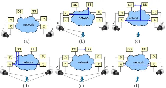
(a) (b) (c)
[image:3.612.142.474.111.288.2](d) (e) (f)
Fig. 1.System implementation with two camerasC1
andC2
(a). The DAD1 detects
a target and sends data to the SS (b). The SS broadcasts target information to both TAsT1andT2(c). The TAs track the target and send their results to the DS (d). The
DS merges the TA results and sends the new target representation to the SS (e). The SS broadcasts the new target representation to all the TAs (f).
A separate TA and DA must be associated with each camera in the system, to track a target in a single camera view and to be able to detect events of interest in each camera view respectively. Conversely, it is reasonable to have a single SS acting as a central hub that receives detections from single DAs and broadcasts these to all the TAs. Concerning data collection, a single DS can act as a sink for the tracking information produced by all the TAs.
In general, for a multi-camera tracking system with N cameras, tracking agent Tn and detection agent Dn are associated with thenth cameraCn with
n∈[1, N], and Fn
i is the ith frame in the nthcamera view. For all the agents,
a single SS and DS are available. As shown in Fig.1b, target information is first sent by a DA (D1) to the SS, upon occurrence of an event of interest. The SS broadcasts this information toT1andT2 (Fig.1c). The TAs send their tracking results to the DS (Fig.1d), which merges them in an attempt to resolve possible inconsistencies and produce a unique multi-camera track of the target. Also, the DS can produce a better representation of the target using information from different TAs; that can then be transmitted from the DS to the SS (Fig.1e), which can then broadcast it again to all the TAs (Fig.1f). This cycle allows for a refinement of the target model, by exploiting characteristics of the target in the different views available in the system.
2.1 DA – Target detection
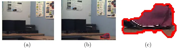
Any DA in the system can select a target within its FOV, upon occurrence of a predefined event of interest. The detection algorithm implemented in the DA is application-dependent and one could either manually select the target, or apply the automatic event detection algorithms [13, 14]. In the current system, our adaptive algorithm for the detection of abandoned and removed objects presented in [15] has been implemented in the DAs. However, differently from [15], the algorithm in the DADnsends to the SS only the camera numbernand
the portion of frameFni corresponding to the selected target (Fig. 2). The reason for this transmission is to further decouple the DAs from the TAs: the TAs can extract from the “image” of the target the features required for their tracking algorithm, without the DAs needing to know what these features and algorithms are. Moreover, separate TAs can implement different tracking algorithms, so they may need to extract different features, such as colour, texture, shape, and so on.
2.2 SS – Target information storage
The SS receives data from a DA, i.e. the portion of frame Fn
i representing the
detected object (Fig. 2) and stores it along with a timestamp, the camera number nand a unique identification numberξfor the target.
The SS acts as a sink for all the DA detections, while it follows a publisher-subscriber pattern with respect to the TAs. More specifically, the SS is always running and the TAs subscribe to it at their setup time. When the SS receives target data from a DA, it broadcasts such information to all its subscribers, i.e. TAs, and also to the DS, so that the DS knows what target, with identification number ξ, is under tracking within the system. The TAs can then look for the new target in their FOVs, and track it if present. The role of the SS is to store and forward data between DAs and TAs, and between DAs and DS.
2.3 TA – Single view target tracking
The TAs perform target tracking in single views, independently of each other. After receiving target information from the SS, a TA is initialised in the current frame when the data from the SS is received. Then the TA performs a loop in which a single step of the selected tracking algorithm is executed on the next
[image:4.612.160.455.571.650.2](a) (b) (c)
frame. If the target has been found, a message with relevant information is sent to the DS. Otherwise, the TA proceeds directly to the next frame. In the rest of the paper, the case where the target has been found by the tracker in the current frame is referred to as “tracking hit”.
Any algorithm can be adopted in the TAs. However, the chosen algorithm must be able to extract discriminative features of the target from the data re-ceived from the SS, in order to overcome the problem of different target appear-ance across multiple FOVs in a multi-camera system. In the current implemen-tation of the system, a modified version of the colour-based IMS-SWAD tracker introduced in [12] is adopted, as described in more detail in section 3.
2.4 DS – Data collation and multi-view tracking
The DS collects tracking results from all the TAs and collates them, to remove inconsistencies and create a unique coherent multi-view track of the target.
In a multi-camera tracking system it is possible to synchronise multiple ma-chines using the Network Time Protocol (NTP), to be able to reliably collate target tracks from different views. However, it is difficult to ensure temporal syn-chronisation at a frame level among multiple trackers. Therefore the presented system adopts a notion of temporal synchronisation in terms of tracking hits falling in the same time interval defined by the DS. This means that the DS defines a time line of consecutive time slotstDSs of given temporal length∆tDS.
The TAs run at their own specific pace and regularly send their tracking results to the DS. Tracking hits flagged by different TAs and received by the DS within the same time slottDS
s are considered to be synchronous.
Similarly, each TA defines a time line of consecutive time slotstT A
s of
tem-poral length∆tT A, and tracking hits in separate frames falling within the same
time slottT A
s are accounted for as a unique tracking hit. At the end of each time
slottT A
s , the TA sends its tracking results to the DS if a target was found in such
a time interval; otherwise no transmission takes place. The information sent by the nth TA includes the camera number n, the target number ξ, a timestamp
and the value of the highest matchλξ
n, for all the tracking hits in time slottT As .
The reason behind defining also a time slottT A
s for the TAs is to avoid the need
to transmit possible tracking hits for every frame processed by a TA.
Having defined time slots for both DS and TAs, timing constraints for the overall system are relaxed and∆tDS and∆tT Acan be set to accommodate the application requirements. As a guideline, assuming the worst case where the DS processes TA notifications sequentially, the lengths of ∆tDS and ∆tT A can be set according to:
∆tDS > N ∆tT X +∆tT A
∆tT A> ∆tT X
∆tT A≥ 1
f psT A
(1)
where N is the number of TAs sending information to the DS, ∆tT X is the
At the end of each time slottDS
s , the DS knows which TAs have found the
targetξin their FOV and which have not. Moreover it can use the match value λξ
nof each tracking hit as a level of confidence for it. When any two TAs,Tn and
Tm, send their tracking hits to the DS for the same target ξ, in the same time
slottDS
s , the DS selects as best view for the time slot∆tDS the view associated
with the tracker that returned the highest match value; therefore the DS can generate a single continuous video stream made up of the portions of video feeds coming from the selected best views, at each∆tDS. Such a strategy is also useful
in overlapping cameras, to be able to select the best view of the target in case of occlusion.
Moreover, as the DS gathers all the tracking hits and collates them, it can be argued that it indirectly performs target tracking across multiple camera views as oppose to a single view in the TAs. Also, the DS can use the gathered data to update the current model of targetξ; the updated model can then be forwarded to the SS, for a new broadcast to all the TAs.
3
Multi-view IMS-SWAD tracking algorithm
The effectiveness of the proposed architecture for multi-camera target tracking is validated using the colour-based IMS-SWAD tracker described in [12]. This colour-based tracker is selected to highlight the fact that the proposed architec-ture does not require any position information of the target or of the cameras. The only required information is whether or not cameras have overlapping FOV. The only modification required in our IMS-SWAD [12] to be integrated within a multi-camera environment is in the initialisation step. After that, the algorithm running in each TA processes its own camera view independently from the oth-ers and therefore it is ideal for a parallel implementation in the context of a decentralised tracking system, as the one described in this paper.
For multi-view colour tracking, colour calibration among all the cameras is required. Therefore the Gray World Assumption [16] is used to colour-normalise all camera views. Such a normalisation is applied to both TAs and DAs. Further, to make the algorithm more resilient to different lighting conditions in separate views, the YCbCr colour space is adopted, but the luminance component Y is removed and only the red and blue chrominance Cb and Cr are used to compute colour distributions.
Knowledge of the camera topology is required for a correct setup of the in-stance of the algorithm in each view. For this purpose the tracking algorithm only needs to know which cameras have overlapping FOVs. Therefore, the re-quired information can be easily encoded with a look-up table (LUT) stating whether two camera views overlap or not. Such an LUT can be provided to each tracker instance, i.e. TA, at setup time. In the context of the decentralised ar-chitecture (section 2), for a targetξ selected in camera Cn, the initialisation of
the trackerTn is same as the one described in [12]. For the otherN−1 trackers
Tm with m 6=n, their initialisation depends on whether the FOVs of cameras
3.1 Non-overlapping camera views
If camerasCnandCmdo not overlap, targetξselected at a given time instant in
Cnis certainly not present inCm. Clearly the position inCmof the best match for
the given target modelQrefers to an object which is not the target. Therefore the threshold τmfor tracker Tm is computed as:
τm= arg min om
l
[d(oml )] (2)
where om
l are the candidate points selected as in the tracker initialisation step
in [12], but with no spatial constraints on their position in the initial frameFm
0 . After initialisation, tracker Tm proceeds to the failure recovery step, as by
definition targetξwas not present inFm
0, so the initial target position inFm1 is undefined. Here it is assumed that, when the targetξenters the FOV of camera Cm, its colour distribution will have a distance d(·) from the target model Q
smaller than any other object in the frame Fm
0 and therefore smaller than τm.
So the trackerTmcan successfully start to track the correct targetξ inCm.
3.2 Overlapping camera views
If camerasCn andCmhave overlapping FOVs, it means that targetξshould be
present in bothFm0 andFn0. The failure recovery procedure applied toFm0 gives the position of the best match for Q in the frame. This best match should be the correct target ξ, assuming that its distribution minimises the distanced(·) fromQ. So trackerTmfinds the correct targetξinFm0 and then proceeds to the next frameFm
1.
If the target ξ is hidden or not visible in Fm
0, the best match found in the frame by the failure recovery procedure will refer to an incorrect targetξ0. This incorrect tracking hit is automatically corrected by the tracker as soon as target ξis visible again in cameraCm, asξgives a higher match thanξ0 and therefore
ξis selected as target to track. However, an initial value for the thresholdτmis
computed anyway and it is updated by the trackerTmin the next frames ofCm.
This approach allows an initial value of the threshold for each camera view to be defined. Such threshold values are soon tuned by the trackers, so potential initial incorrect hits are confined to a small number of frames. Moreover possible tracking inconsistencies across different views can be resolved by the DS at data collation time as explained in section 2.4.
4
Experimental results
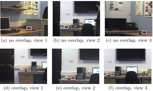
(a) no overlap, view 1 (b) no overlap, view 2 (c) no overlap, view 3
[image:8.612.162.454.114.289.2](d) overlap, view 1 (e) overlap, view 2 (f) overlap, view 3
Fig. 3.Indoor testing: non-overlapping (top row) and overlapping (bottom row) views.
4.1 Tracking performance
The tracking performance of the system is numerically evaluated in terms of precision, recall, specificity and accuracy [1]. In all the experiments in this paper, the ground truth is manually annotated by putting a bounding box around the main colour of the chosen target.
As a first experiment, two multi-camera indoor video sequences have been recorded, respectively one with three non-overlapping views and one with three overlapping views (Fig.3). In this experiment, the target (a pink cap), which is manually moved from view to view, has been automatically detected by the algorithm implemented in the DAs, in one of the views and then tracked by the TAs in the other two views (Fig.3). This is repeated for all views to obtain a total of six tests (1-6) for both cases. After target detection in the DA, the portion of frame corresponding to the selected target is sent to the SS (section 2.1). As it is difficult to make sure that pre-recorded sequences are re-run synchronously during testing, the TA activity is simulated by launching one TA per sequence at the time. Each TA initially subscribes with the already running SS, which in turns sends to the TA the target information previously stored. The TA computes the target model needed and tries to track the target in its corresponding video sequence. In this way the target is then tracked in all six tests.
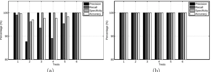
Numerical values of such tests compared with the manually labelled ground truth in Fig.4 show that the system has high precision, recall, specificity and accuracy, i.e. more than 85% in all 12 tests. In the overlapping case in particular, neither False Positives nor False Negatives have been detected (Fig.4b). These results indicate that the system and in particular its current implementation, has good tracking performance in an indoor environment.
1 2 3 4 5 6 80
90 100
Tests
Percentage (%)
Precision Recall Specificity Accuracy
(a)
1 2 3 4 5 6 80
90 100
Tests
Percentage (%)
Precision Recall Specificity Accuracy
[image:9.612.136.480.119.237.2](b)
Fig. 4.Results for indoor testing with (a) non-overlapping views (b) overlapping views.
#72 of sequence 2. The target image is then sent to the SS and from there to the TA for each of the six PETS2009 sequences. The target is therefore tracked in all sequences as it moves across camera views. Of these video sequences, the sequences 1, 2 and 3 and sequences 4, 5 and 6 are synchronised with each other, which means that the nthframe in each sequence refers to the same instant in
time and it has a counterpart in the other two sequences (Fig. 5). It can be observed from Fig. 5 how the target may not be visible at times in some of the views (e.g. Fig. 5e), while it can still be tracked at the same time instant, i.e. same frame number, in other views (e.g. Fig. 5b and 5h). This aspect is fundamental for selecting the best view of a target, at any time.
Further, from numerical values in Fig. 6, it can be seen that the system has high precision and specificity also in an outdoor setup, with only 4 False Positives erroneously detected in all six sequences. In general, recall and accuracy are also high (>90%), apart from sequence 6, where the lower value of recall (83%) is due to the fact that in this sequence the target walks away from the camera and its size decreases to less than half of the original. In this case, the histogram of the target changes significantly, resulting in a poor match and therefore a high number of False Negatives. This second experiment indicates the effectiveness of the proposed architecture, in terms of communication between SS and TAs, also in an uncontrolled environment, such as outdoor sequences.
4.2 Best view selection and occlusion handling
In the proposed system, the DS receives information on tracking hits, i.e. camera numbern, target numberξand match valueλξn, from each TA which has found
(a) sequence 4, frame #479 (b) sequence 4, frame #507 (c) sequence 4, frame #716
(d) sequence 5, frame #479 (e) sequence 5, frame #507 (f) sequence 5, frame #716
[image:10.612.136.483.126.456.2](g) sequence 6, frame #479 (h) sequence 6, frame #507 (i) sequence 6, frame #716
Fig. 5.Synchronised images from PETS2009 sequences 4 12.34-05), 5 (S2-L1-12.34-06) and 6 (S2-L1-12.34-07) with correct target highlighted by tracking algorithm.
1 2 3 4 5 6 80
90 100
Sequences
Percentage (%)
Precision Recall Specificity Accuracy
Fig. 6.Precision, recall, specificity and accuracy for six PETS2009 sequences.
Moreover, the DS can use the tracking results from the TAs associated with overlapping cameras, to select at any time the view with the highest TA match λξ
[image:10.612.221.393.490.596.2]best view: 1
1 2 3
(a)
best view: 3
1 2 3
(b)
best view: 2
1 2 3
[image:11.612.137.479.120.253.2](c)
Fig. 7.Three images from the DS: the system is able to switch between camera views wherein the target is detected, to create a continuous video stream of the target.
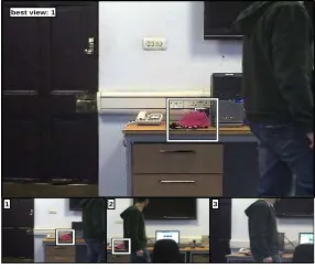
best view: 1
1 2 3
Fig. 8.DS with best view selection: the target is occluded in view 3; partially occluded in view 2; completely visible in view 1.
cameras, when the target is occluded in one of the views. As illustrated in Fig. 8, the target is correctly tracked in views 1 (λξ1= 76.4%) and 2 (λξ2= 44.5%). As view 1 gives higherλξnvalue, it is selected as best view among the three available
ones, and occlusion is implicitly solved.
5
Conclusion
[image:11.612.236.379.293.415.2]and therefore possible tracking loss. However, the IMS-SWAD itself can be ex-panded to include other features, such as texture, which should help differentiate between correct target and such other objects with similar colour. Nontheless, the proposed multi-camera architecture would not require any modification. The system is ideal in situations where video synchronisation and detailed knowledge of cameras’ setup is not available.
References
1. A. Smeulders, D. Chu, R. Cucchiara, S. Calderara, A. Dehghan, and M. Shah.: Visual Tracking: An Experimental Survey. IEEE Transactions on Pattern Analysis and Machine Intelligence36(7) (2014) 1442-1468.
2. X. Wang.: Intelligent multi-camera video surveillance: A review. Pattern Recogni-tion Letters34(1) (2013) 3-19.
3. R. T. Collins, A. J. Lipton, H. Fujiyoshi, and T. Kanade.: Algorithms for cooperative multisensor surveillance. Proceedings of the IEEE89(10) (2001) 1456-1477. 4. R. Tron and R. Vidal.: Distributed computer vision algorithms. IEEE Signal
Pro-cessing Magazine28(3) (2011) 32-45.
5. P. Remagnino, A. I. Shihab, and G. A. Jones.: Distributed intelligence for multi-camera visual surveillance. Pattern Recognition, Elsevier37(4) (2004) 675-689. 6. M. Taj and A. Cavallaro.: Distributed and decentralized multicamera tracking. IEEE
Signal Processing Magazine28(3) (2011) 46-58.
7. A. Ercan, A. Gamal, and L. Guibas.: Object Tracking in the Presence of Occlusions Using Multiple Cameras: A Sensor Network Approach. ACM Trans. Sen. Netw. 9
(2) (2013) 16:1-16:36.
8. O. Javed, K. Shafique, Z. Rasheed, and M. Shah.: Modeling intercamera spacetime and appearance relationships for tracking across nonoverlapping views. Computer Vision and Image Understanding109(2) (2008) 146-162.
9. E. Lobaton, R. Vasudevan, R. Bajcsy, and S. Sastry. A distributed topological cam-era network representation for tracking applications. IEEE Transactions on Image processing19(10) (2010) 2516-2529.
10. F. Porikli and A. Divakaran.: Multi-camera calibration, object tracking and query generation. in International Conference on Multimedia and Expo (2003) I-653-656. 11. B. Moller, T. Plotz, and G. A. Fink.: Calibration-free camera handover for fast and reliable person tracking in multi-camera setups. in International Conference on Pattern Recognition (2008) 1-4.
12. G. Di Caterina and J. Soraghan.: A robust, precise and flexible tracking algorithm based on IMS and SWAD. in IEEE International Conference on Acoustics, Speech and Signal Processing (2014) 6588-6592.
13. A. Adam, E. Rivlin, I. Shimshoni, and D. Reinitz.: Robust real-time unusual event detection using multiple fixed-location monitors. IEEE Transactions on Pattern Analysis and Machine Intelligence30(3) (2008) 555-560.
14. T. DOrazio and C. Guaragnella: A Survey of Automatic Event Detection in Multi-Camera Third Generation Surveillance Systems. Int. J. Patt. Recogn. Artif. Intell.
29(1) (2015) 1555001–1–29.
15. G. Di Caterina and J. J. Soraghan.: An abandoned and removed object detection algorithm in a reactive smart surveillance system. in International Conference on Digital Signal Processing (2011) 1-6.
16. G. Buchsbaum. A spatial processor model for object colour perception. Journal of The Franklin Institute310(1) (1980) 1-26.