1
Simulation Study of FACTS Devices Based on AC-AC Modular
Multilevel Hexagonal Chopper
Peng Li *, Grain P. Adam, Derrick Holliday, Stephen J. Finney, Barry W. Williams
Electronic and Electrical Engineering Department, University of Strathclyde, Royal College Building, 204 George Street, Glasgow, UK, G1 1XW
*
Abstract: This paper proposes a new range of FACTS device based on direct AC-AC conversion, where the modular multilevel AC hexagonal chopper (M2AHC) is employed. The M2AHC is operated in quasi-two-level (Q2L) mode; and the heterodyne modulation is used to decouple voltage amplitude regulation from the phase shift; thus, independent control of active and reactive power is achieved. Then, a family of FACTS devices based on M2AHC that offers voltage, active power and reactive power flow control as both shunt and series compensators is analyzed. The use of AC cell capacitors instead of DC capacitors in M2AHC makes its footprint much smaller and lighter than conventional AC-DC or DC-AC voltage source converter (VSC) based FACTS devices; hence, high reliability and extended service life could be expected. The system modeling and controller design of the proposed FACTS devices are illustrated in a unified reference frame, considering different control modes, transient and unbalanced conditions. Simulation results are used to verify the feasibility of the proposed M2AHC based FACTS device. These FACTS devices will be preferred over conventional counterpart for confined spaced applications such as the grid access of large-scale offshore wind farms and resolution of loop flow in megacities.
1. Introduction
Recently, to deal with the increasing decentralized and meshed power grid driven by the penetration of large-scale distributed renewable energy sources, the use of flexible AC transmission system (FACTS) devices has been encouraged to offer enhanced system controllability and equipment utilization; thus, fulfilling the requirements for more and more complex power dispatch tasks to dispersed load centers [1-3].
The voltage source converter (VSC) based FACTS devices such as static synchronous compensator (STATCOM), static synchronous series compensator (SSSC) and unified power flow controller (UPFC) have been proven to be effective for autonomous voltage and reactive power control, manipulation of shunt reactive current for attenuation of low-order harmonic currents, active power flow control and correction of voltage unbalance through line impedance manipulation. Thus, any attempt to reduce passive component cost, size, weight; and enhancing the control range compared with thyristor based solutions are advantageous [4, 5]. Two-level converter is the basic topology for VSC-FACTS devices. To reduce the voltage stress on power switches and dv/dt of interfacing transformers in high voltage applications, various multilevel converters have been applied in this area [6-8].
2 high cost and short service life of the large DC-link capacitor bank is currently one of the main constraints hampering the spread of FACTS devices.
Due to this reason, researchers have started to investigate the direct AC-AC solutions without DC-link to be used as voltage compensators and power flow controllers. The matrix converter is employed in [11, 12], where the steady state modelling and control are analyzed. Vector switching converter may reduce the number of switches compared to matrix converter but requires the multi-throw input transformer as power sources [13]. AC chopper is conventionally viewed as voltage amplitude regulator without phase shift ability. By cross connection of different phases in multi-phase system, both voltage amplitude regulation and phase control are achieved but coupled together. Although a series of heterodyne method based techniques in [14-16] for vector switching converter, AC chopper and high frequency link AC converter have been developed to offer decoupled power control ability, the high switching frequency and lack of modularity (direct series connection of power switches) may hamper their extension beyond low and medium voltage applications.
Modular AC-AC converters such as modular multilevel cascaded converter (MMCC) and Hexverter that use full-bridge chain-links enjoy full modularity as in DC-AC modular multilevel converter (MMC) [17, 18]. However, in these converters, the bulky DC cell capacitors are still required; thus, the footprint is large and service life is limited.
Modular multilevel AC hexagonal chopper (M2AHC) is proposed in [19], where its topology and operational principle are thoroughly discussed. It offers true scalability for high-voltage applications by introducing pure AC modular switching cells. With the heterodyne modulation, independent control of voltage amplitude and phase angle is achieved by M2AHC; thus, facilitating the decoupled control of active/ reactive power without DC decoupling stage. Also, its hexagonal structure can circulate zero sequence byproduct inside the converter, avoiding extra devices for filtering.
This paper uses M2AHC to create a new range of FACTS devices. Case studies of its representative FACTS device configurations with controller design are interpreted to handle the steady state operation, transient and unbalanced conditions. Some technical discussions and major findings are highlighted. 2. M2AHC in Quasi-Two-Level Mode with Decoupled Voltage Amplitude and Phase
Control
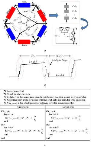
3 modularity for high voltage application, avoiding the difficulty on direct series connection of large number power switches. Other than direct voltage level transition as in the basic chopper circuit (two-level), M2AHC offers a quasi-two-level (Q2L) operation that divides the voltage level transition into multiple small steps as in Fig. 1(b).
a
b
[image:3.595.148.450.136.622.2]c Fig. 1. The summarization of M2AHC
a Converter configuration with its arm and cell structures b Q2L operation mode.
c Generic code for Q2L operation of M2AHC with cell capacitor voltage balancing.
4 control the voltage level transition rate as in Fig. 1(b). The generic code for the M2AHC to implement its Q2L operation with AC cell capacitor voltage balancing can be summarised in Fig. 1(c). In this manner, typical staircase multilevel voltage waveform is generated at microscopic level (within each switching cycle) instead of over full fundamental cycle in typical multilevel operation. Such operation reduces the switching dv/dt that will be exerted on the interfacing transformer due to continuous chopping of the ac voltage, especially around the peak voltage.
Q2L operation facilitates generation of multilevel voltage waveform within very short time for each voltage step (slightly exceed the switch turn-off time); thus, the period of each cell capacitor being charged or discharged by the load current is extremely short, see Fig. 1(b). This, as well as the AC nature of each cell capacitor, drastically reduces the energy requirements of the switching cells in the M2AHC, hence, its footprint [19]. In fact, the small ac cell capacitors of M2AHC behave similarly as a snubber but in an orderly controlled manner (stepped voltage level transition). As long as the voltage balancing strategy in Fig. 1(c) is adopted, the maximum voltage over each single switch of the M2AHC during high voltage switching transient can be effectively clamped by its cell capacitor.
In Fig. 1(b), since the voltage step duration δt for Q2L operation of the M2AHC is far smaller than its switching period Ts, the two arms per phase in Fig. 1(a) works similarly as two switches in a basic
chopper that conduct complementarily. Therefore, recall Fig. 1(a), the input line voltages are denoted as {vAB, vBC, vCA}, and {da, db, dc} are the duty cycles for the conduction of three-phase upper arms. Then, if
the Q2L duration is neglected for simplifying the control analysis, the M2AHC output line voltage can be expressed by (1).
(1 )
(1 )
(1 )
oAB AB a BC b oBC BC b CA c oCA CA c AB a
v v d v d
v v d v d
v v d v d
(1)
If the duty cycle of M2AHC contains only constant DC component, its output voltage amplitude and phase regulation cannot be decoupled for lacking control degree of freedom. Based on trigonometric identity of (2), the heterodyne modulation is able to utilize the harmonic modulating signals as new control variables. For example, as in [19], the 2nd order negative sequence signal is incorporated in the duty cycles to decouple the fundamental voltage amplitude and phase angle of M2AHC in positive sequence.
5 Moreover, to compensate higher order harmonics, a wider range of high frequency modulating signals need to be further used but require sufficient high switching frequency. This paper focuses on the context of grid transmission level, where no high order harmonic distortion is considered and switching frequency is not recommended to go beyond several kilohertz; therefore, no higher order signal components beyond those in (3) are employed, which guarantees a reasonable switching frequency of M2AHC for high power grid-scale applications, in order to limit the switching losses.
1 2
coscos [cos( ) cos( )] (2)
0 0 2 2
2 2
3 3
0 0 2 2
2 2
3 3
0 0 2 2
cos cos( 2 )
cos( ) cos( 2 )
cos( ) cos( 2 )
a dc b dc c dc
d k k k t
d k k k t
d k k k t
(3)
If the input line voltage of M2AHC is expressed in (4), by manipulating trigonometric identities of (1), (3) and (4), the zero sequence voltage byproducts are cancelled in the output line-to-line voltage; and the output voltage can be decoupled into (5) and (6), where {vd +, vq+} and {vd-, vq-} are positive and
negative sequences d-q components of the fundamental output phase voltage, respectively.
2 3 2 3 cos cos( ) cos( ) AB m BC m CA m
v v t
v v t
v v t
(4)
1
2 2 2
1 1
2 3 2 2
(2 1 cos )
( sin )
d m dc
q m
v v k k
v v k (5)
1
2 0 0
1
2 0 0
cos sin d m q m
v v k
v v k (6)
From (5) and (6), it is observed that the M2AHC with heterodyne modulation is able to generate voltage vectors with independent amplitude and phase-shift; thus, fully decoupling the active and reactive power flow control and offering voltage unbalanced mitigation when applied as FACTS devices.
3. FACTS Devices Based on M2AHC
6
[image:6.595.83.513.49.161.2]
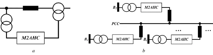
a b Fig. 2. Representative configurations of M2AHC based FACTS devices
a Series compensator
b General multi-bus power flow controller (GMPFC)
M2AHC based FACTS devices synthesize amplitude-phase independent AC voltage from the input. Compared to the magnetic and mechanical phase shift transformer (PST), the uses of zig-zag windings plus the on-load tap changers can be avoided; thus, the size is significantly reduced and higher flexibility is achieved. Besides, in relative to the conventional DC-AC based FACTS devices, the cost and service-life of proposed solutions are largely optimized due to the absence of DC capacitor and the modularity for M2AHC.
4. Generic Modeling and Control Design of M2AHC Based FACTS Devices
In this section, the series compensator of Fig. 2(a) is selected as representative candidate for modeling and control analysis; then, the GMPFC in Fig. 2(b) which involves multiple M2AHC units is investigated to offer the loop flow regulation for multiple grid buses.
4.1. M2AHC Based Series Compensator
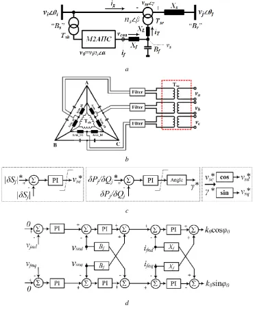
The detailed configuration of Fig. 2(a) is shown in Fig. 3(a), where vi=vi∠θi and vj= vj∠θj are the two
bus voltages on Bs and Br; Xs represents the power line reactance carrying a current of ig; ni∠α is the input
shunt transformer voltage ratio; vse=vse∠γ is the series injected voltage by the series interfacing transformer
Tse with fixed phase shift angle β and turns ratio ns; Xf, XL and Bf are impedance and susceptance of the
7 of input delta-connected filter capacitor bank is used (alternatively, the delta type secondary winding of Tsh
can be mid-tapped) to serve as the reference terminal of the output phase independent windings for voltage series injection, which is topologically similar as the DC-AC inverter for bipolar voltage generation. In this manner, the phase output voltage is zero at 0.5 duty cycle; thus, its active and reactive power control range could be optimized to match that of the conventional AC-DC solutions.
a
b
c
[image:7.595.112.482.163.620.2]d Fig. 3. The series compensation device using M2AHC
a The equivalent circuit of M2AHC series compensator
b Per phase differential mode connection for optimized power control range c Power flow control layer
8
4.1.1 Power Flow Model Analysis: For simplicity, the modeling process focus on normal operation without
unbalanced disturbance and all power losses are neglected. If the bus voltage vi is the input, from (5), the M2AHC output voltage with configuration in Fig. 3(b) is expressed by (7) and (8).
vcon v0AH H vi ni AHH (7)
2 2
2 2 2 2 2
1 2 2
3(2 1) 3 (6 3) cos 3 sin
4 2
3(2 1) 3 cos
cos [ ]
2 2 dc dc H dc H H
k k k k k
A
k k
A
(8)
With the given parameters in Fig. 3(a), the output current of the M2AHC and the grid current after compensation can be expressed by (9) and (10). Then, the nodal power flow equations Scon and Sse representing the complex domain power flows of the M2AHC output terminal and power injection point are calculated using (11) [20]. By substituting the converter output voltage equation (7) into (11), the real and imaginary parts of Scon and Sse are achieved after a group of algebraic manipulations to express the active and reactive power components as in (12) and (13). Notice that ni, ns, α, β, We, Xf, XL and Bf are all
known and fixed parameters.
2 1 1 L f
e s e
f f s e s e
X B
jW jn W
X B
jn W jn W
f con
g se
i v
i v (9)
We X X BL f f Xf XL (10)
2 * * 1 * 1 * L f
e s e
f f
s e s e
X B
jW jn W
X B
jn W jn W
f con con se se g con se con se con se i S v v S i
v v *
v v
v * v
(11)
se
2 2 2
se 2 se 2 sin ( 1) cos (1 ) cos
i H i con se
s e
L f i H i i H i con
e s e
f f se i H i se
s e s e
n A v v
P P
n W
X B n A v n A v v
Q
W n W
X B v n A v v
Q
n W n W
9 H i (13) The injected voltage vse is able to independently control the active and reactive power flow between
vi and vj. Based on the power injection model in [21], the incremental power flow on the receiving bus Br
is calculated by (14). By solving the power flow mismatch equations, the local compensator instructions vse, γ, AH, ΔH can be determined [21].
sin( ) cos( )
j se j j
s j se j j s v v P X v v Q X (14)
4.1.2 System Control Design: In [19], the controller design for M2AHC with LCL filter is discussed, which is divided into three layers and implemented in d-q frame. As a series type compensator, the incremental active power and reactive power of receiving bus Br are set to be the control targets, with the
reference voltage vi as input of phase-locked-loop (PLL).
2 2
| |=
/ tan( )
j se
j j j
s
j j j
v v
S P Q
X
P Q
(15)
Based on the power injection model in (14), independent control of active and reactive power flow is obtained by manipulation of voltage amplitude and phase as in (15). Thus, the power control layer can be clarified by Fig. 3(c), where the obtained reference signals of vse and γ are used to generate the d-q
frame references {vsd*, vsq*} for next levels. Then, the intermediate and inner control layers presented in
[19] can be employed to modulate the M2AHC for power flow regulation.
4.1.3 Ride-Through Ability for Unbalanced Condition: During voltage unbalanced operation, the series type
M2AHC can act as DVR to implement the voltage unbalance mitigation based on (6). By differentiating the DC component of the heterodyne modulating signal in each phase with k0cosφ0, k0cos(φ0-2π/3) and
k0cos(φ0+2π/3), an independent negative sequence component of the fundamental can be generated. This
component can be exploited to manipulate the M2AHC to ease the disturbed load bus voltage when it suffers from unbalanced voltage or power flow.
If vjnd and vjnq are the direct and quadrature components of the negative sequence disturbance in load
bus voltage vj, to suppress them to be zero, and from Fig. 3(a), the M2AHC unit should contribute certain
10 corresponding output state variables of M2AHC in negative sequence. The obtained pair of control outputs {k0cosφ0, k0sinφ0} is employed to synthesize the required DC differential signals for voltage compensation
mode (unbalanced power flow ride-through).
4.2. Generalized Multi-bus Power Flow Controller
a
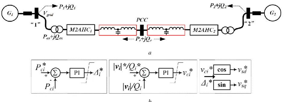
[image:10.595.63.541.161.330.2]b
Fig. 4. The general multi-bus power flow controller (GMPFC) based on M2AHC
a Atomic connection of GMPFC with two M2AHC F2F units b Power control blocks for GMPFC based on F2F M2AHC devices
As in Fig. 2(b), the GMPFC integrates multiple AC grid buses into a PCC hub, where each two M2AHC units resemble the front-to-front (F2F) configuration. With this scheme, the active and reactive power flow of each grid is able to be controlled autonomously or achieve desired operational objectives set by high-level supervisory controller such as the supervisory control and data acquisition (SCADA) [22]. The atomic connection with two F2F connected M2AHCs is plotted in Fig. 4(a). For simplicity of illustration, this paper uses the voltage droop to realize active and reactive control at the PCC hub.
It is noticed that, with the F2F terminals, the bias voltages at 0.5 modulating signals are cancelled between each two M2AHC units; thus, the symmetrical and doubled power flow control range can be achieved using basic shunt interfacing transformers avoiding the tapped winding structures in Fig. 3(b) for single M2AHC series compensator.
For an m-buses power network with the GMPFC installed, there are m-1 pairs control degrees of freedom considering the law of energy conservation. The control block for GMPFC is shown in Fig. 4(b), where bus i is assumed for general cases. Neglecting all losses on the M2AHC, the bus active power mismatch is always equal to that through the PCC port which is denoted as Pci. Thus, in Fig. 4(b), Pci is
11 can be regulated by the converter output voltage amplitude vci. The generated signals Δi* and vci* are
transferred as voltage references for inner control layer of each M2AHC unit.
GMPFC also offers potentiality for voltage support if one grid bus voltage drops. In this case, the converter connected to the fault bus works in boost mode with pure DC modulating signals to supply step-up ability for bus voltage rebuild.
5. Performance Evaluation
[image:11.595.142.453.312.441.2]In this section, to verify the effectiveness of the proposed approach, an 11-level M2AHC model with 10 AC switching cells per arm is built in Matlab/Simulink software environment. Based on this model, the performance of M2AHC series compensator in Fig. 3(a) is investigated to show its power flow and voltage control ability in various grid conditions. Then, the GMPFC that contains two converter units as in Fig. 4(a) is simulated to prove its functionality on the power and voltage regulation of a meshed grid.
Table 1 Converter specifications for simulation 10-cell M2AHC
Apparent power rating Scon 100MVA AC input line-to-line voltage vL 55kV(RMS)
AC cell capacitor Ccell 10μF Arm inductor Larm 10μH Filtering capacitor Cf 100μF Output filtering stage 10mH+47μF
[image:11.595.143.456.476.620.2]Q2L time duration 5μs Switching frequency fsw 1.8kHz
Table 2 Interfacing transformer parameters Shunt transformer
Power capacity 100MVA
Winding type Y/Y
Voltage ratio 110kV/55kV Per unit impedance (0.0005+j0.08)
Series transformer
Power capacity 100MVA Winding type Phase independent Voltage ratio 15.88kV/15.88kV Per unit impedance (0.0002+j0.05)
Table 3 AC transmission system parameters
Grid parameters for series compensation
Three-phase short circuit level 1.91GVA Nominal line voltage 110kV(RMS)
[image:11.595.141.454.655.713.2]12 The specifications of the M2AHC employed in the following simulations are listed in Table 1; also, the parameters for the transformers and AC grid are shown by Table 2 and Table 3 respectively.
5.1. Device level tested results
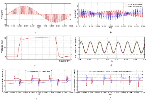
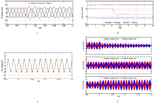
The device level results of the M2AHC converter operation are briefly summarized as in Fig. 5. Fig. 5(a) is the chopped AC voltage on the output terminal of M2AHC and Fig. 5(b) shows the chopped arm currents respectively. The zoom-in version of the output voltage with multilevel steps in Q2L operation is displayed by Fig. 5(c). Also, the voltage balancing result for 20 AC cell capacitors of phase A can be observed in Fig. 5(d). Fig. 5(e) and (f) show the snapshots of the two arm currents and power switch currents in each cell that are zoomed over few switching cycle. Observe that upper and lower arms of the same phase leg conduct simultaneously (common-mode current) only during stepped transitions of the output phase voltage. Otherwise, the entire load current flows through one arm and no current flows in the other arm.
a b
c d
[image:12.595.48.550.312.656.2]e f Fig. 5. Key waveforms of the M2AHC operated in Q2L mode
a Chopped output voltage b Chopped arm currents
13 e Zoomed-in version of the upper and lower arm currents
f Zoomed-in current waveforms for the switches in each cell
5.2. M2AHC as Series Compensator for Power Flow Control
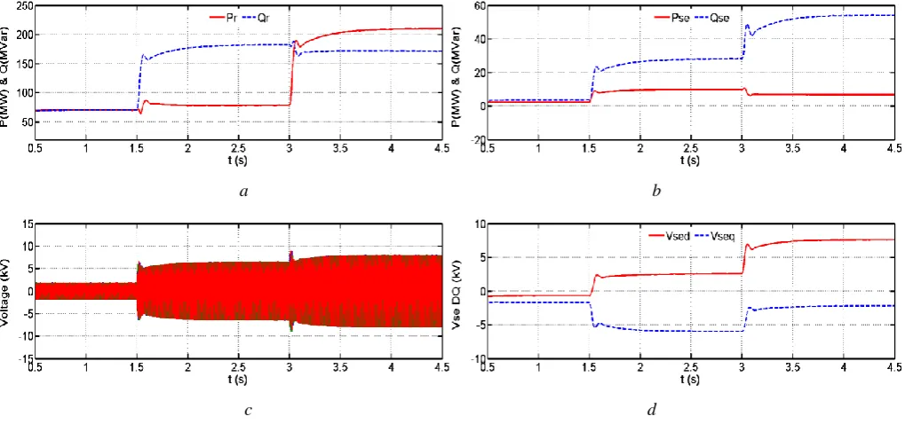
The presented M2AHC based series compensator of Fig. 3(a) is first tested in power flow control mode. The control targets are set to be the active and reactive power reference tracking for the receiving bus. Initially, the grid line receives a power flow of 70MW+j70MVar. At t=1.5s, the reactive power command is stepped to 180MVar; then, at t=3s, the active power command is increased to 210MW.
Fig. 6(a) shows the active and reactive power flow at the receiving power bus. Notice that during the above power flow transitions, the M2AHC compensator contributes small active power and significant reactive power as it control the power flow in the main line, see Fig. 6(b). Correspondingly, Fig. 6(c) and (d) display the series injected voltage in time domain and its d-q version when M2AHC operates in power flow control mode. Observe that d-q components of inserted voltage are widely manipulated as it controls the grid power flow. Fig. 6(e) and (f) show the samples of the cell capacitor voltages and arm currents zoomed around t=1.5s (when step change is applied as stated above). These plots indicate that the current and voltage stresses on the switching devices and cell capacitors of the M2AHC are fully controlled before and following the step change. Note that the cell capacitor voltages exhibit no visible transients because of the small ac cell capacitors and arm inductors. These indicate the M2AHC based series compensator in Fig. 3(a) can perform both functionalities of conventional SSSC and UPFC.
a b
[image:13.595.44.554.438.677.2]14
[image:14.595.51.552.52.168.2]e f Fig. 6. Power flow regulation using the M2AHC series compensator
a Active and reactive power flow in grid line b Power exchange between compensator and grid c Series injected voltage in time domain
d Series injected voltage in d-q frame
e Cell capacitor voltages during power flow transient process f Arm currents during power flow transient process
5.3. M2AHC Based Series Compensator for Voltage Flicker and Unbalance Mitigation
In recent decades, with the decentralization process of power system and the heavy penetration of intermittent renewable energy sources into the grid, operation under unbalanced voltage conditions in medium-voltage distribution systems is becoming increasingly challenging due to the large number of single-phase loads, unbalanced loads and DG sources connected at lower distribution voltage [23, 24]. Assuming bus terminal Brin Fig. 3(a) is weak and disturbed by uneven power flow in the line, two cases
are examined: flicker phenomenon and unbalanced load.
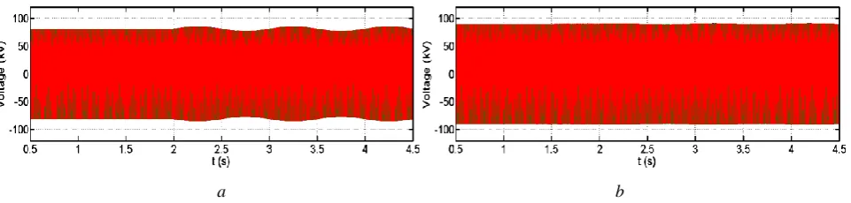
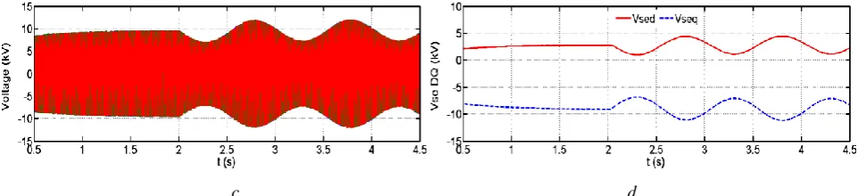
For illustration of flicker mitigation, a dynamic load that mimics a typical flicker with 1Hz oscillation frequency is connected at weak receiving bus Br at t=2s. Such flicker risk is expected to be a
common problem with the increasing penetration of medium-scale wind farms at the distribution systems. Fig. 7(a) shows that the voltage waveform at Br is heavily flickering with 1Hz frequency without
compensation. Whilst this bus voltage can be controlled nearly flicker free (constant) after enabling the M2AHC series compensator that operates in voltage control mode (similar with the dynamic voltage restorer, DVR) as in Fig. 7(b). Fig. 7(c) and (d) show the series injected voltage waveform by M2AHC in time domain and d-q frame respectively.
[image:14.595.60.541.596.711.2]15
[image:15.595.58.539.58.168.2]c d Fig. 7. Voltage flicker immunization using the M2AHC series compensator
a Flicker phenomenon without compensation
b Flicker-free bus voltage with the proposed compensator c Injected voltage in time domain
d Injected voltage in d-q frame
The load unbalanced condition will also bring influence to the weak bus voltage. In Fig. 3(a), assuming the unbalanced fault happens at 2s, the load bus voltage without compensation is displayed in Fig. 8(a). In this case, the control block in Fig. 3(f) for the M2AHC series compensator is activated, by which the unbalanced negative sequence component can be eliminated as in Fig. 8(b). Thus, bus voltage can keep balanced. Fig. 8(c) is the series injected unbalanced voltage by the M2AHC FACTS device. In further, the positive sequence and negative sequence components of the compensator voltage are shown in d-q frame by Fig. 8(d). Observe that the proposed M2AHC series compensator adjusts the d-q components
of the negative sequence in order to mitigate the voltage balanced at Br. Fig. 8(e) and (f) present samples
of the cell capacitor voltages and arm currents zoomed around t=2s (when voltage unbalanced is initiated). The cell capacitor voltages remain unaffected by the load side unbalance. Notice that the different arm currents of three phases reflect the different output currents of individual phases that contribute to the correction of voltage unbalance.
[image:15.595.49.550.508.623.2]16
c d
[image:16.595.43.561.58.395.2]e f
Fig. 8. Voltage-unbalance compensation using M2AHC series compensator
a Unbalanced disturbance without compensation b Balanced voltage with the proposed compensator c Injected voltage in time domain
d Injected voltage in d-q frame
e Cell capacitor voltages balancing results during unbalanced load disturbances f Arm currents response for generating unbalanced voltage
Based on the above results, it is verified that the proposed M2AHC series compensator is capable of managing the grid power flow; besides, it can implement the voltage compensation function during disturbances. In this sense, it is expected that the conventional SSSC, UPFC and DVR could be replaced by the proposed M2AHC based solutions in certain conditions.
5.4. Simulation Study for Multiple M2AHCs Operated as GMPFC
17 At first, the nodal active and reactive power is controlled by the M2AHC output voltage droop (PQ mode). The initial power flow at bus “1” is P1+jQ1=160MW+j40MVar; and when t=2s, Q1 is reduced
from 40MVAr to -10MVAr; then at t=5s, P1 is increased from 160WM to 190MW, as observed in Fig.
9(a). In Fig. 9(b), the M2AHC voltage droop forces the nodal power flow to track their references. Fig. 9(c) represents the power exchanged by the M2AHC based device. During the transitions, the current response in the converter hub is displayed in Fig. 9(d). The zoomed-in converter hub current and voltage waveforms are shown in Fig. 9(e)-(f), respectively.
a
b c
d e
[image:17.595.52.545.198.636.2]
f Fig. 9. Key waveforms for F2F M2AHC device in PQ control mode
a The circuit diagram of F2F M2AHC acting in PQ control mode b Nodal power flow response in PQ control mode
c Power exchange between M2AHC device and grid d PCC current inside the converter hub
18 f Zoomed in version of the converter AC hub voltage
Then, the GMPFC is set to maintain the voltage amplitude on node “1” and regulate the active power flow exchanged between AC grids “1” and the M2AHC device (PV mode). Initially, the F2F device supplies zero active power to node “1”. The active power command for the M2AHC device Pex is stepped
to 30MW at t=2s, and an incremental power of 30MW+j30MVar is added on the bus “1” to the initial power flow P1+jQ1 at t=4s and removed at t=6s, see Fig. 10(a). During these transitions, the power flow
response at bus “1” is shown in Fig. 10(b). Also, observe that the proposed GMPFC device is able to maintain the grid voltage amplitude by regulating the injected reactive power and at the same time force the active power exchange to track the reference as displayed by Fig. 10(c) and (d). Then, the waveform of the current flowing into the PCC at the converter hub can be observed in Fig. 10(e).
a
b c
[image:18.595.54.540.273.594.2]d e Fig. 10. Key waveforms for F2F M2AHC device in PV control mode
a The circuit diagram of F2F M2AHC acting in PV control mode b Nodal power flow response in PV control mode
c Grid nodal voltage amplitude
19 The proposed GMPFC with F2F arrangement of M2AHC offers independent active and reactive power control for power flow optimization in highly meshed grid as well as the voltage support ability during disturbances.
6. Discussion
To highlight the attributes and limitations of the proposed scheme, a high-level comparison between the M2AHC (delta-connected), the star-connection version of the proposed converter and the conventional DC-AC MMC, all employed as series connected FACTS devices, are summarized in Table 4. In this comparison, the desired converter output phase voltage for series injection is Vse (peak value) and N cells
are required per arm to block the input voltage of Vse; also, for given apparent power capacity Scomp, the
phase current of DC-AC converter Ib is calculated and used as the current base for the following
comparison.
To generate the given AC voltage Vse, the MMC requires a DC-link of at least 2Vse; hence, 62N
cells are needed for three-phase MMC. As shown in Fig. 3(b), the M2AHC and its star-connected version require the input AC voltages of 2√3Vse and 2Vse, respectively; then, the number of cells can be calculated
accordingly (62√3N and 62N).
In further, the total number of switches and current rating of power switches can be quantified as in Table 4. Notice that in MMC, two arms per phase must conduct continuously; therefore, 50% of its total devices are in conduction path, carrying half of the output current (0.5Ib) plus DC component (Idc) for
active power transfer. On the other hand, due to the Q2L operation mode, only one arm in each phase conducts in the proposed AC-AC converter for major time of fundamental period, which means 25% devices carry full output current (Ib). Besides of the fundamental current, the M2AHC circulates 3rd order
harmonic current in its arm; while MMC arm current contains fundamental plus DC components (for active power transfer) as well as a certain amount of 2nd order harmonics.
20 With the AC-AC conversion nature of M2AHC, two transformers are required to connect to the grid reliably as in the back-to-back MMC configuration.
Table 4 High-level comparison between the M2AHC, star-connected modular AC chopper and MMC based series FACTS devices (Assumptions: desired phase output voltage is Vse (peak value); N cells per armare needed to block the input voltage equal to 1pu of Vse; Scomp represents the required compensation capacity for each candidate; current base Ib is defined by
𝟐𝑺𝒄𝒐𝒎𝒑 𝟑𝑽𝒔𝒆 ).
Candidate Name M2AHC
Modular AC chopper in
star-connection
MMC-SSSC MMC-DVR MMC-UPFC Total blocking
voltage per arm ≥ 2√3Vse ≥2Vse ≥2Vse ≥2Vse ≥2Vse Minimum number
of cells for three-phase
62√3N 62N 62N 62N
262N for back-to-back configuration Number of
switching devices for three-phase
462√3N (4 IGBTs per cell)
462N (4 IGBTs per cell)
262N (2 IGBTs per cell)
262N (2 IGBTs per cell)
2262N (2 IGBTs per cell)
Capacitor requirement
Small AC filter capacitor and Small AC cell capacitors
Small AC filter capacitor and Small AC cell capacitors
Large DC cell capacitors
Large DC cell capacitors
Large DC cell capacitors Power management Active and reactive power Active and reactive power Only reactive power Active and reactive power Active and reactive power External active dc
source No No
No (unable to exchange active
power)
Yes (to exchange
active power) No Number of
transformers 2 2 1 1 2
Footprint and total
energy storage Small Small Large Large Very large Number of
switches in conduction path
for three-phase
25% of total switches: 62√3N
25% of total switches: 62N
50% of total switches: 62N
50% of total switches: 62N
50% of total switches: 262N
Current rating per switch
full phase current (1
√3Ib)
full phase current (Ib)
50% of the phase current; unable to transfer active power; hence, no DC current (12Ib)
50% of the phase current (Ib) plus DC common mode
currents Idc for active power transfer (12Ib+Idc)
50% of the phase current (Ib) plus DC common mode
currents Idc for active power transfer (12Ib+Idc) Conduction losses Moderate Relatively high Low Low Relatively high
Switching losses Relatively high Relatively high Low Low Moderate Arm current
harmonics mainly 3
rd
order mainly 3rd order mainly 2nd order mainly 2nd order mainly 2nd order
Dynamic response Fast Fast
Slow (limited by cell capacitor
dynamics)
Slow (limited by cell capacitor
dynamics)
Slow (limited by cell capacitor
dynamics) Functionalities All SSSC, DVR
and UPFC
All SSSC, DVR
and UPFC SSSC SSSC and DVR
All SSSC, DVR and UPFC Power flow direction Bidirectional power flow Bidirectional power flow Bidirectional reactive power Bidirectional power flow Bidirectional power flow
21 7. Conclusion
This paper has proposed a new breed of FACTS devices using modular multilevel AC hexagonal chopper (M2AHC) for enhanced power quality and power flow control to meet the challenge of increasing dispersed power generation and highly meshed grid topology. The main contributions of this work are summarized as follows:
1) By adopting the direct AC-AC scheme, the footprint of the M2AHC based power flow controller is reduced for the absence of sizable DC capacitors. The modularity and reduced switch number make the M2AHC competitive with matrix converter.
2) M2AHC with heterodyne modulation can act as typical VSC with independent control of active and reactive power. Also, an extended version heterodyne modulation is employed in this paper to generate fully controlled negative sequence voltage components for the unbalanced grid compensation.
3) Potential use of M2AHC as various FACTS devices are discussed; and its local controller has been analysed to perform the key functionalities of existing FACTS devices such as STATCOM, SSSC and UPFC. The transient performance of M2AHC under power flicker and grid unbalance disturbances are presented using the detailed model with sufficient number of cells
4) In particular, a generic multi-bus power flow controller (GMPFC) is proposed in this paper to integrate multiple grids into an AC converter hub for better utilization of the transmission capacity. Also, this front-to-front (F2F) configuration of the M2AHC is able to offer extended power flow control range.
8. References
[1] X. Ying, Y. H. Song, L. Chen-Ching, and Y. Z. Sun, "Available transfer capability enhancement using FACTS devices," Power Systems, IEEE Transactions on, vol. 18, pp. 305-312, Feb 2003. [2] J. Mutale and G. Strbac, "Transmission network reinforcement versus FACTS: an economic
assessment," Power Systems, IEEE Transactions on, vol. 15, pp. 961-967, Aug 2000.
[3] O. Goksu, R. Teodorescu, C. L. Bak, F. Iov, and P. C. Kj, "Impact of wind power plant reactive current injection during asymmetrical grid faults," IET Renewable Power Generation, vol. 7, pp. 484-492, 2013.
[4] B. Singh and V. S. Kadagala, "Simulation of three-level 24-pulse voltage source converters-based static synchronous compensator for reactive power control," IET Power Electronics, vol. 7, pp. 1148-1161, 2014.
[5] J. S. S. Prasad and G. Narayanan, "Minimum switching loss pulse width modulation for reduced power conversion loss in reactive power compensators," IET Power Electronics, vol. 7, pp. 545-551, 2014.
22 [7] D. Sixing and L. Jinjun, "A Study on DC Voltage Control for Chopper-Cell-Based Modular Multilevel Converters in D-STATCOM Application," Power Delivery, IEEE Transactions on, vol. 28, pp. 2030-2038, 2013.
[8] F. P. Zeng, G. H. Tan, J. Z. Wang, and Y. C. Ji, "Novel single-phase five-level voltage-source inverter for the shunt active power filter," IET Power Electronics, vol. 3, pp. 480-489, 2010.
[9] B. Gultekin and M. Ermis, "Cascaded Multilevel Converter-Based Transmission STATCOM: System Design Methodology and Development of a 12 kV/12 MVAr Power Stage," IEEE Transactions on Power Electronics, vol. 28, pp. 4930-4950, 2013.
[10] S. Liu, T. Bi, K. Jia, and Q. Yang, "Coordinated fault-ride-through strategy for doubly-fed induction generators with enhanced reactive and active power support," IET Renewable Power Generation, vol. 10, pp. 203-211, 2016.
[11] O. Boon-Teck and M. Kazerani, "Unified power flow controller based on matrix converter," in Power Electronics Specialists Conference, 1996. PESC '96 Record., 27th Annual IEEE, 1996, pp. 502-507 vol.1.
[12] S. Rajendran, U. Govindarajan, and D. S. P. Sankar, "Active and reactive power regulation in grid connected wind energy systems with permanent magnet synchronous generator and matrix converter," IET Power Electronics, vol. 7, pp. 591-603, 2014.
[13] J. M. Ramirez, J. M. Gonzales, and M. L. Crow, "Steady state formulation of FACTS devices based on ac/ac converters," Generation, Transmission & Distribution, IET, vol. 1, pp. 619-631, Jul 2007.
[14] L. A. C. Lopes, G. Joos, and O. Boon-Teck, "A high power PWM quadrature booster phase-shifter based on a multi-module converter," in Power Electronics Specialists Conference, 1995. PESC '95 Record., 26th Annual IEEE, 1995, pp. 375-380 vol.1.
[15] D. M. Divan, D. M. Divan, and J. Sastry, "Voltage Synthesis Using Dual Virtual Quadrature Sources - A New Concept in AC Power Conversion," Power Electronics, IEEE Transactions on, vol. 23, pp. 3004-3013, Nov 2008.
[16] L. Chushan, D. Yan, L. Zibo, L. Wuhua, H. Xiangning, and W. Yousheng, "Virtual Quadrature Source-Based Sinusoidal Modulation Applied to High-Frequency Link Converter Enabling Arbitrary Direct AC-AC Power Conversion," Power Electronics, IEEE Transactions on, vol. 29, pp. 4195-4208, 2014.
[17] W. Kawamura, M. Hagiwara, and H. Akagi, "A broad range of frequency control for the modular multilevel cascade converter based on triple-star bridge-cells (MMCC-TSBC)," in Energy Conversion Congress and Exposition (ECCE), 2013 IEEE, 2013, pp. 4014-4021.
[18] L. Baruschka and A. Mertens, "A New Three-Phase AC/AC Modular Multilevel Converter With Six Branches in Hexagonal Configuration," Industry Applications, IEEE Transactions on, vol. 49, pp. 1400-1410, May-Jun 2013.
[19] P. Li, Y. Wang, G. Philip Adam, D. Holliday, and B. W. Williams, "Three-Phase AC-AC Hexagonal Chopper System With Heterodyne Modulation for Power Flow Control Enhancement," Power Electronics, IEEE Transactions on, vol. 30, pp. 5508-5521, 2015.
[20] Y. Zhang, Y. Zhang, and C. Chen, "A Novel Power Injection Model of IPFC for Power Flow Analysis Inclusive of Practical Constraints," IEEE Transactions on Power Systems, vol. 21, pp. 1550-1556, 2006.
[21] M. Noroozian, L. Angquist, M. Ghandhari, and G. Andersson, "Use of UPFC for optimal power flow control," Power Delivery, IEEE Transactions on, vol. 12, pp. 1629-1634, 1997.
23 [23] A. P. d. Moura and A. A. F. d. Moura, "Analysis of injected apparent power and flicker in a distribution network after wind power plant connection," IET Renewable Power Generation, vol. 2, pp. 113-122, 2008.
[24] R. Chilipi, N. A. Sayari, K. A. Hosani, and A. R. Beig, "Control scheme for grid-tied distributed generation inverter under unbalanced and distorted utility conditions with power quality ancillary services," IET Renewable Power Generation, vol. 10, pp. 140-149, 2016.