IAC–16–D2.7.7x35697
DEPLOYED PAYLOAD ANALYSIS FOR A SINGLE STAGE TO ORBIT SPACEPLANE
Federico Toso∗, Christie Alisa Maddock† Centre for Future Air Space Transportation Technologies
University of Strathclyde, Scotland, United Kingdom
The growth of the small satellite market requires an affordable and flexible launcher to satisfy the demand for insertion to a varied range of specific orbits. This paper presents the application and results of a tool created for the preliminary analysis of a reusable lifting body vehicle to address the demand of small to medium sized payloads. Trajectory optimisation is performed on the ascent mission of the launcher from a nominal cruise altitude to the release of the payload into different orbits with different mission and vehicle objectives and constraints. Two vehicle configurations are studied and applied to test cases of insertion to 200 km circular orbits at different inclinations. Further analysis on the performances obtained at different altitudes is conducted to study the effect on maximum payload mass. The advantages and limitations of the single stage to orbit approach are discussed and ways to overcome the latter are further analysed with the introduction of a small upper stage or tug. This additional engine can perform small manoeuvres to correct the flight path for orbital insertion, which expands the type of orbits that can be reached, and is integrated in the optimisation routine. The overall performance of the different launch systems are optimised for each mission, and compared against each other looking at the total payload mass and required mass fraction to reach different orbits.
I INTRODUCTION
One of the possible options to launch payloads into space has always been the single stage to orbit ve-hicle (SSTO). While there are many theoretical ad-vantages, this type of vehicle has never been flown because of either technological obstacles or design complexity. The progress of material sciences, new manufacturing processes and the growth in compu-tational performances of the new century are making the case of a commercial SSTO a viable one.
Conventional expendable rockets are limited on the mass fraction delivered to orbit by the rocket equation. Different options exist to increase the pay-load mass fraction, the most common is to introduce staging which can improve the overall mass fraction by splitting the ∆V gained in each stage.
A second option is one exploited by SSTO vehicles of increasing the effective exhaust velocity. Given the equationve=Ispg0 there can be up to a tenfold
in-crease in efficiency1due to the fact that air-breathing engines do not have to carry the oxidizer onboard and thus have higher specific impulse. In addition, a lifting body can offset aerodynamic drag and gravi-tational losses using the lift generated by the wings. These losses may add up to 15% of the ∆V required
∗PhD student, [email protected]
†Lecturer, [email protected]
to achieve orbit.
Improvements in propulsion technology, and demonstrations from companies like Reaction En-gines with their SABRE pre-cooler proved that many of the integral components work both in theory and in practice; moving closer towards the realisation of high supersonic air-breathing engines. Moreover, while rockets are close to their ideal maximum efficiency and have improved relatively little in the last decades, supersonic and hypersonic air-breathing engines stud-ies are still in their infancy and have plenty of room to improve.2 Other advantages of the SSTO vehicles
are derived from the horizontal take off and landing configuration that allows integration of the payload on the ground without tilting the vehicle, re-usability, abort capabilities designed to save both the launcher and the payload, reduced complexity due to absence of staging or air launch, and the promise of operations similar to commercial airliners with quick turnaround between missions.
The design methodology starts from this assump-tion in order to size the launcher: considering a vari-able margin for dry vehicle and payload, the propul-sion, aerodynamic surfaces and initial mass are opti-mised with the objective of minimising the propellant needed for the mission. The mission is a full simu-lation of the trajectory, from the start of the ascent at the end of the cruise phase to the payload release in the desired orbit. The spaceport taken into con-sideration is Glasgow Prestwick, the choice is done to demonstrate the flexibility of this platform even for applications in high latitude locations that are less penalized for polar or sun-synchronous orbits but have a disadvantage for low inclination and equatorial orbits. Once the vehicle is sized for a LEO mission, the penalty of reaching other inclinations and alti-tudes is evaluated, discussing the reduction in pay-load capability. The reference missions analysed are for the launch of small satellites up to 1000 kg into a 200 km altitude Earth orbit, with two different in-clinations taken into consideration. The mission is analysed starting after take-off and initial climb up to the release of the payload in the target operational orbit.
The optimisation is done using a highly modular code that can easily trade computational speed for model fidelity in each of the system models used.3, 4
The trajectory can be subject to multiple constraints that are easily modifiable for each mission such as no fly zones, maximum acceleration due to structural limitations, thermal flux and thermal load threshold as a consequence of the specific thermal protection system considered.
II SYSTEM MODELS
The mathematical models used in the mission opti-misations are presented in the following section. The system models were developed for a preliminary anal-ysis to work within a multidisciplinary design opti-misation, and can be grouped into vehicle system models, including aerothermodynamics and propul-sion, and operational and environment models for the Earth and atmosphere, and flight dynamics and con-trol.
All the mathematical models used in this work are applied within a modular software environment, al-lowing a variable complexity with multiple levels of fidelity to satisfy the requirements during different phases of the mission, and to reduce the computa-tion run time of the mission analysis.
II.I Vehicle configuration
The SSTO vehicle configuration was modelled based on a scaled down version of the Skylon D1 vehicle de-sign using publicly available data and analyses. The Skylon D1 vehicle is a reusable SSTO designed by Reaction Engines to have the advantage of airline operations with easy payload integration thanks to horizontal take off and landing procedures and the advantage of using a highly efficient air breathing en-gine in the atmospheric phase of the ascent to increase the mass fraction brought to orbit. The SABRE en-gine is rated to generate T = 2 MN of thrust per nacelle, with two powerplants installed. The design gross take off weight ismGT OW = 325 metric tons in
the D1 configuration, 85% of which is the sum of fuels and payload, with the latter beingmP ayload= 15 ton
for an equatorial launch to a circular orbit of 300km with inclinationi= 0. From a launch site positioned at a higher latitude λ = 55 deg, the mass in orbit decreases to mP ayload = 13 ton in a low inclination
circular orbit of 200 km of altitude. II.II Aerothermal
The aerodynamic forces are computed using the lift and drag coefficients for a conceptual hypersonic test vehicle Lazarus,5 which focused on the development of aerodynamic laws for the purpose of scaling the performances of a SSTO vehicle in MDO. The valid-ity of the value and method are dependent on the vehicle design. In the case here, the two vehicle con-figurations are similar enough to allow the values to provide a first approximation of the aerodynamic per-formances of a spaceplane with a maximum aerody-namic efficiency of 3. Using the standard equations for lift and drag forces, the coefficients are multiplied for the dynamic pressure q = 12ρV2 of the fluid and
the surface areaSref of the wings, which is one of the
design parameters involved in this study.
The thermodynamic model is responsible for the limitation of the trajectory upon atmospheric re-entry. The Sutton Graves equation6 is a simplified method that conservatively assumes a fully catalytic surface to estimate the convective heating received by the wall. In the case of LEO re-entry of a lifting body, the contribution of the convective heating is many orders of magnitude higher than the radiative one that is therefore neglected.
qconv=k
ρ
Rn 1/2
V3 [1]
With the increase in surface temperature, the body will start radiating heat following the Boltzmann law,
qrerad=σ T4−T∞4
[2] The emissivity = 0.8 is set for a non ablative ceramic thermal protection and σ = 5.67× 10⁻⁸
W/m2/K4 is the Stefan-Boltzmann constant.
Ne-glecting the material response due to the lack of the ablation and charring processes, and with the rea-sonable assumption that the TPS is a particularly good insulator, the heat flux balance is assumed to be qconv =qrerad. From this relation, the wall
tem-peratureTW can be determined.
TW =
T∞4 +qconv σ
1/4
[3] While this effect is not affecting the ascent trajecto-ries, analysis that focus on the re-entry phase or long duration hypersonic flight in the atmosphere are con-strained to satisfy the limits of the chosen thermal protection system.
II.III Propulsion
Two propulsive modes are taken into consideration: air-breathing and rocket mode. The engine models have been created to fit publicly available SABRE datapoints.7 The rationale that led to the selection
of this particular engine are the same one that made Skylon the configuration of choice for this analysis. According to the Skylon User Manual, Rev 2.1, each of the nacelles in the air breathing mode is rated for a gross thrust from 0.8 to 2 MN, functioning from a standing start to Mach 5.5, with a specific impulse varying between 4000 and 9000 seconds. The rocket mode is less efficient, with a 450 s specific impulse, generating 2 MN of thrust. While the manual reports that this latter propulsive mode works from Mach 5.2 onward, it is most likely a consequence of the as-cent profile of the Skylon vehicle, since the rocket en-gine would produce thrust independently of the flight speed.
Based on the available data, an approximate propulsive law is derived. The air-breathing mode of the engine model is set to reach peak efficiency at Mach 3.5 and 100% throttle and the decrease in atmospheric density negatively impacts the perfor-mances of the engine. This effect is achieved by low-ering the specific impulse when the flight conditions change. The rocket engine does not have Mach de-pendence but has lower thrust at the higher pressure conditions found at low altitudes due to the nozzle expansion losses.
The last analysis presented introduces an upper stage with a small rocket powered orbital manoeu-vring system for orbit insertion and correction. This engine model is set to generate a maximum force of T = 4.9 kN to avoid the possibility of having a thrust to weight ratio above one. The specific impulse Isp= 250 s is a conservative assumption and a
typi-cal value for storable propellants which are not high efficiency engines but a common solution for payload integrated propulsion systems or upper stages that require multiple restarts. The nozzle exit area is as-sumed to have a diameter de= 1 m.
II.IV Environment
The WGS84 geodetic system is used considering the oblateness of the Earth spheroid for the determina-tion of the radial distance of the Earth surface rE.
The gravitation model is based on spherical harmon-ics accounting for the J2, J3 and J4 terms based
on the radial distances to the Earth surface rE and
to the vehicle r, and the latitude λ. The gravita-tional acceleration is calculated for the radial and transversal components, g = grˆir+gtˆit.8 The
an-gular rotation of the Earth is assumed constant at ωE= 7.292115×10⁻⁵rad/s.
The atmosphere is modelled using the globally av-eraged International Standard Atmosphere. For each value of flight altitude, there is a corresponding out-put of pressure and temperature used to comout-pute density and sound speed. The ISA is a valid model till h= 84852 m, above which the altitude pressure and density are set to zero, while temperature is fixed toT = 186.87 K to limit the speed of sound to a con-stant value.
II.V Flight dynamics and control
The vehicle is modelled as a point mass in an Earth Centered Earth Fixed (ECEF) reference frame with 3 degrees of freedom for all the phases of the mis-sion. The dynamics for the transatmospheric flight are the same for ascent or descent. Within this model, the spaceplane is considered as a point with a time-varying mass centred on the Centre-of-Mass of the vehicle. The set of equations of motion are calcu-lated within a geocentric rotating reference frame us-ing spherical coordinates, denoted by F.
γ and the flight heading angle χ. The equations of motion are given by,8
˙
h= ˙r=vsinγ [4a]
˙
λ=vcosγsinχ
r [4b]
˙
θ=vcosγcosχ
rcosλ [4c]
˙
v=FTcos(α+ε)−D
m −gsinγ [4d]
+ωe2rcosλ(sinγcosλ−cosγsinχsinλ) ˙
γ=FTsin(α+ε) +L
mv cosµ−
g
v − v r
cosγ [4e] + 2ωecosχcosλ
+ωe2r v
cosλ(sinχsinγsinλ+ cosγcosλ) ˙
χ= L
mvcosγsinµ−
v
r
cosγcosχtanλ [4f] + 2ωe(sinχcosλtanγ−sinλ)
−ωe2
r
vcosγ
cosλsinγcosχ [4g]
whereαis the angle of attack,µis the bank angle,m is the mass of the vehicle, εis the pitch offset angle between the direction of thrust FT and the
longitu-dinal plane of the vehicle, g is the gravitational ac-celeration, andLandDare the aerodynamic lift and drag forces, respectively. With the exception ofε, all the terms are time-varying. FT is the magnitude of
the thrust given by the engine.
Looking at a standard aircraft body-relative ref-erence frame B, +xB is towards the nose along the longitudinal axis of the spaceplane, +yB is outwards along the wing, and +zB points downwards towards the Earth normal to the plane of symmetry given by xB-yB. The flight path angle is the angle between the local horizon (defined by as the plane tangent to the radial vector) and the velocity vector, while the flight heading angle is the angle between North (or thexF -axis) and the horizontal component of the velocity vector.
The orbital parameters necessary to compute the constraints relative to the final operational orbits are computed with a conversion of the local east-north-up coordinates to the ECEF spheroid-centric Cartesian. The rotation of the earth is added to obtain the Earth Centered Inertial expression required to calculate the required orbital elements of semimajor axisa, eccen-tricityeand inclinationi. With this additional infor-mation is possible to introduce the constraints needed to obtain circular and sun synchronous orbits.
III OPTIMISATION APPROACH
A multidisciplinary optimisation was used to evalu-ate the performance of the vehicles. The trajectory is divided into multiple phases, each with specific op-timisation settings and models to best represent the system and environment. This approach can be used to handle mathematical singularities such as the aero-dynamic coefficient at transonic speeds by having a subsonic phase followed a supersonic one with en-forced matching constraints on the state variables, simulate staging with instantaneous mass changes or to switch propulsion models such the one here from the air-breathing to rocket mode. Every phase is set up to have specific mathematical models for the en-vironmental variables, the aerodynamic and propul-sive forces, thermal constraint evaluations, dynamic equations, number of multi-shooting elements, con-trol nodes in each element, minimum and maximum bounds for states and controls and time of flight.
III.I Optimal control
The optimal control problem is formulated with a di-rect transcription, multiple shooting method in which every phase is divided intonm segments withnc
dis-crete control nodes. The time of flight of each seg-ment is an optimisation variable, and is used to derive the time distribution of the control nodes based on a Tchebycheff distribution which biases the points to-wards the two extremes of the segments. Conditions are added to match the state and control variables between segments, dependant on the formulation of the phases. For example, to account for mass drops during staging, the matching condition for the vehicle mass is removed.
Each segment is numerically integrated using a 4th order Runge Kutta with a fixed time step. The value of the timestep is an input variable and can be set de-pending on the phase analysed, allowing larger time steps for phases such as a coasting arc.
The controls are determined using a piecewise cu-bic Hermite interpolation of the open loop control law.
III.II Local optimisation
The optimisation of the problem is performed using Matlab nonlinear constrained optimisation function
propellant mass used for the ascent once either the fi-nal (dry) or the initial gross take-off masses are fixed. Equality constraints are added to ensure that the relevant state and control variables are connected be-tween elements of the trajectory (phases and shooting segments) and that the final orbit is reached based on matching the semi-major axis, eccentricity and incli-nation.
Inequality constraints are set to ensure the ther-mal limits of the TPS are satisfied, TW ≤ 2000 K,
and that the axial and normal accelerations induced on the vehicleax,z ≤6g0. A constraint is set to
en-sure the final mass is higher than the dry mass of the vehicle,m(t=tf)≥mdry.
III.III First guess
The first guess is selected by performing a multi-start global search. The number of sample points is in-creased linearly with the growth of the number of variables of the problem. The starting values are dis-tributed on the search space using the latin hyper-cube sampling technique to better explore the search space. To efficiently sort through all the starting points, a large simulation timestep is used to reduce the computational run time. In addition, the optimi-sation tolerances on the constraints are relaxed and the maximum number of iterations reduced to achieve a fast selection of the first guesses.
Once the multiple starting points have been evalu-ated and the best local solution has been found, this solution is re-optimised using an iteratively reduced timestep until a minimum timestep is reached (based on the input criteria) with tightened (or un-relaxed) constraints. This incremental increase in complex-ity greatly reduces computational time required to generate a feasible first guess while adding some ex-ploration capabilities to the optimisation process.
IV TEST CASE
The setting for the ascent optimisation of the SSTO are listed in Table 1. The unconstrained heading an-gle is an advantage of the lifting body vehicle that can initiate the ascent procedure from a level flight in the optimal direction. Starting latitude and longitude are set to be in a small area around the departure spaceport of Glasgow Prestwick.
IV.I Vehicle scaling
For the first analysis, used to size the vehicle, the mass at the start of the ascent phase is an
optimisa-tion parameter. Since the cost funcoptimisa-tion of the optimi-sation is the minimioptimi-sation of the fuel used for ascent, the dry mass of the vehicle has to be constrained. The dry weight to GTOW ratio of the Skylon vehicle is 15% and assuming this baseline value, a penalty coefficient of 4.44% per 100 metric tons was imposed. While it can be argued that the mass increase due the size reduction does not take into account fixed con-tribution of the avionics and other constant weights, there is a compensating effect due to the decrease of the thickness of the thermal protection system. While the weight scales with the third power of the linear measure, the surface scales with the square of the length, guaranteeing a lower ballistic coefficient. The sizing is performed aiming to deliver a 1 ton payload to a low inclination circular orbit of 200 km. The op-timised value of starting mass found is m0 = 90035
kg, not accounting for the fuel needed for ascent from the runaway to the starting simulation altitude.
A simple scaling of the masses would leave the vehicle with overestimated aerodynamic and propul-sive forces. To eliminate the issue and further study the optimal configuration, a variable is introduced to scale the performance of the engine and the aero-dynamic surfaces. The scaling factor is the same for the forces generated by the wings and by the engines. This avoids an excessive reduction of the wings whose contribution in the ascent phase is much smaller com-pared to that of engine. This protects the necessary wing area, giving a suitable L/D ratio assuming a glided descent phase.
The optimal configuration is found scaling to 96.11% of the forces generated by Skylon’s wings and SABRE thrust. This configuration reaches LEO at 200 km with a final mass ofmf = 24189 kg including
payload. The high values of the forces does not vio-late the 6g acceleration limit imposed along the tra-jectory (along both the axial and normal directions), a standard value of many payload launchers, and al-lows a substantial reduction of gravity losses with a fast ascent since most of the aerodynamic losses are in the early phases of low altitude flight.
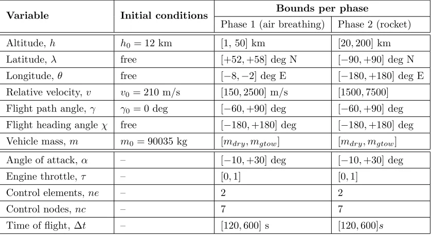
Table 1: Boundary conditions on state and control variables for the SSTO vehicle reaching a 200km orbit
Variable Initial conditions Bounds per phase
Phase 1 (air breathing) Phase 2 (rocket)
Altitude,h h0= 12 km [1, 50] km [20,200] km
Latitude,λ free [+52,+58] deg N [−90,+90] deg N
Longitude,θ free [−8,−2] deg E [−180,+180] deg E
Relative velocity, v v0= 210 m/s [150,2500] m/s [1500,7500]
Flight path angle, γ γ0= 0 deg [−60,+90] deg [−60,+90] deg
Flight heading angleχ free [−180,+180] deg [−180,+180] deg Vehicle mass, m m0= 90035 kg [mdry, mgtow] [mdry, mgtow]
Angle of attack,α – [−10,+30] deg [−10,+30] deg
Engine throttle,τ – [0,1] [0,1]
Control elements,ne – 2 2
Control nodes,nc – 7 7
Time of flight, ∆t – [120,600] s [120,600]s
force more efficiently than the rocket motor in a nar-row region outside of the desired operating regime. After this point in the high supersonic regime, the engine is switched to the rocket operational mode till the end of the main ascent phase. Despite this, the quality of the solution is shown by the low inclina-tion of the final orbit on the ground track in the latitude-longitude plane and from the coasting arc before the final circularisation burn to enter the or-bit. With more accurate propulsion models, the al-gorithm can be a useful tool to aid the choice of the optimal switching point.
IV.II Payload analysis in different orbits
After sizing the vehicle and having fixed the param-eters that influence the forces, the penalty to access different orbits is studied. Each of the analysed or-bits is computed with a dedicated optimisation run to evaluate the mass margin available. The mass margins are studied relative to the different charac-teristic orbital energies computed with the formula C3 = v2−µE/r where µE is the standard
gravita-tional parameter of the Earth and r and v are the radial distance and velocity relative to the inertial frame of reference. Each value ofC3energy identifies
a group of orbits by combining the contribution of different orbital parameters and is an effective figure of merit in tradeoff studies.
From the obtained results in Fig. 1 we can see how
sensitive the design margin of a 1 ton payload is, and how by slightly increasing the target orbit altitude or inclination, the available payload mass is quickly re-duced to negative values. To mitigate this issue, one of the possibilities is to design a larger vehicle that can carry more fuel in order to access high inclination orbits such as the sun synchronous (SSO).
Using the same approach detailed in the previous section, a second vehicle is designed choosing a retro-grade sun synchronous circular orbit with an altitude of 200 km as target for the same amount of payload. The result obtained is a SSTO vehicle with a initial mass m0 = 147650 kg and a force fraction of 99%.
As seen in Fig. 1, this new configuration is able to achieve a sun synchronous orbit, and deliver a pay-load greater than 1 ton to lower inclinations. The heavier 150 t vehicle shows the same drop-off trend in mass fraction with an increase in altitude as the 90 t vehicle.
IV.III Addition of an upper stage
-4000 -3000 -2000 -1000 0 1000 2000 Payload mass [kg]
-61 -60.5 -60 -59.5 -59 -58.5
Characteristic energy [MJ/kg]
SSTO 90t, low incl SSTO 150t, SSO
(a) Payload delivered by the SSTO to different orbits at the respective design inclination.
0.2 0.21 0.22 0.23 0.24 0.25 0.26 0.27 Payload mass fraction [%]
-61 -60.5 -60 -59.5 -59 -58.5
Characteristic energy [MJ/kg] SSTO 90t, low inclSSTO 150t, SSO
[image:7.612.87.525.92.225.2](b) Remaining mass fraction at orbit insertion.
Fig. 1: Results obtained for different target orbits betweenh= 200 km andh= 400 km by the two vehicle configurations, expressed as both residual payload and mass fraction. Dashed lines highlight the respective dry mass limits and fractions.
-4000 -3000 -2000 -1000 0 1000 2000
Payload mass [kg] -61
-60 -59 -58 -57
Characteristic energy [MJ/kg]
SSTO 90t, low incl SSTO 150t, SSO 2 stages, low incl. 2 stages, SSO
(a) Comparison of the vehicle configurations with and without upper stage for both sun synchronous and low inclination orbits fromh= 200 km toh= 600 km.
700 750 800 850 900 950 1000 Payload mass [kg]
-61 -60 -59 -58 -57
Characteristic energy [MJ/kg]
2 stages, low incl. 2 stages, SSO
[image:7.612.316.524.319.443.2](b) Zoomed area of Fig. 2(a) highlighting the perfor-mances of the 2 staged approach for both SSO and low inclination orbits betweenh= 200 km andh= 600 km.
Fig. 2: Performances obtained by the SSTO vehicle and the approach with two stages, with a more detailed view of the latter.
payload that could also be used for end of life decom-missioning.
The performance metric analysed, the final mass, includes the payload spacecraft, the propulsive sys-tem and any required subsyssys-tem needed for the oper-ations after release from the reusable launcher stage. A coasting phase without thrust is introduced in the optimisation routine at the end of the ascent of the first vehicle that was designed for 1000 kg of payload in a h= 200 km low inclination circular orbit. This unpowered phase has only one control node to link the angle of attack and bank angle from upper stage release to the final circularisation phase. This last flight segment has the task of performing a burn on the apogee to raise the perigee of an elliptical orbit
till the value of eccentricity ise= 0.
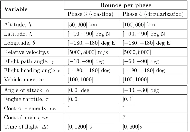
Table 2: Additional Boundary Conditions and Bounds on State and Control Variables for the introduction of the upper stage targeting a 200km orbit
Variable Bounds per phase
Phase 3 (coasting) Phase 4 (circularization)
Altitude,h [50,600] km [100,600] km
Latitude,λ [−90,+90] deg N [−90,+90] deg N Longitude,θ [−180,+180] deg E [−180,+180] deg E Relative velocity,v [5000,8000] m/s [5000,8000]
Flight path angle, γ [−60,+90] deg [−60,+90] deg Flight heading angleχ [−180,+180] deg [−180,+180] deg Vehicle mass, m [100,1000] [100,1000] Angle of attack,α [0,0] deg [−30,+30] deg
Engine throttle,τ [0,0] [0,1]
Control elements,ne 1 1
Control nodes,nc 1 7
Time of flight, ∆t [0,1200] s [0,600]s
IV.IV Upper stage performance analysis
As can be seen in Fig 2(a), the introduction of the upper stage produces a drastic increase of the orbits that can be reached by the payload with a small sac-rifice in final mass. This behaviour greatly offsets the penalty of altitude, allowing small payloads to reach high energy orbits. A magnification of the area of the new datapoints is shown in Fig. 2(b), highlight-ing how even for the high altitudeh= 600 km orbits the final mass is still positive andmf ≥700 kg.
While the increase in payload due to the addition of an extra stage is obvious, the particularly interest-ing result is the fact that the trajectories are numeri-cally evaluated case by case, and most of the solutions found are lined up on a front that can be considered a good performance metric for the robustness of the optimisation routine, especially in the low inclination orbit group. An additional confirmation can be de-ducted by the fact that the solution for the 200 km low inclination case are extremely close to the 1000 kg value found without the upper stage even though no information were used from the SSTO case to gen-erate the new data.
V CONCLUSION
A modular MDO approach was used to evaluate the performance of a SSTO vehicle examining the
pay-load mass that can be delivered against different or-bits, using the vehicle mass fraction against the char-acteristic energy of the orbit.
A reference vehicle design was obtained for a ref-erence orbit. This vehicle was then used to analyse the performance at higher altitude and different in-clination orbits, extrapolating a set of solutions that analysed on the payload-energy graph show the per-formances and limitations of the approach. The sharp decrease in payload due to the final altitude increase is mitigated by the introduction of an additional stage that drastically reduces the effect.
From these preliminary results, it is shown how designing a vehicle for a specific orbit limits the pos-sibilities to expand the range of operations outside of the predetermined bounds and, if some effects are not taken into account, a vehicle may be unable to meet the expectations of a varied set of customers.
REFERENCES
[1] Segal, C., The scramjet engine: processes and
characteristics, Vol. 25, Cambridge University
Press, 2009.
[3] Pescetelli, F., Minisci, E., Maddock, C., Taylor, I., and Brown, R., “Ascent Trajectory Optimisa-tion for a Single-Stage-to-Orbit Vehicle with Hy-brid Propulsion,”AIAA/3AF International Space Planes and Hypersonic Systems and Technologies
Conference, 2012.
[4] Toso, F., Maddock, C., and Minisci, E., “Opti-misation of Ascent Trajectories for Lifting Body Space Access Vehicles,” Space transportation so-lutions and innovations symposium, International
Astronautical Congress, 2015.
[5] Young, D. A., Kokan, T., Clark, I., Tanner, C., and Wilhite, A., “Lazarus: A SSTO Hy-personic Vehicle Concept Utilizing RBCC and HEDM Propulsion Technologies,” International Space Planes and Hypersonic Systems and
Tech-nologies Conference, AIAA, 2006.
[6] Sutton, K. and Graves Jr, R. A., “A general stagnation-point convective heating equation for arbitrary gas mixtures,” 1971.
[7] Hempsell, M., Longstaff, R., and Bond, A., “SKYLON Users Manual,” Reaction Engines
Limited, Vol. 1, 2010.
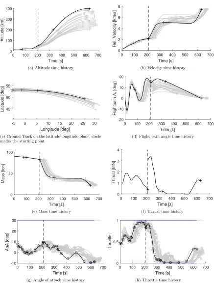
0 100 200 300 400 500 600 700 Time [s]
0 100 200 300 400
Altitude [km]
(a) Altitude time history
0 100 200 300 400 500 600 700 Time [s]
0 2 4 6 8
Rel. Velocity [km/s]
(b) Velocity time history
-5 0 5 10 15 20 25 30
Longitude [deg] 45
50 55
Latitude [deg]
(c) Ground Track on the latitude-longitude plane, circle marks the starting point
0 100 200 300 400 500 600 700
Time [s] -20
-10 0 10 20
Flightpath A. [deg]
(d) Flight path angle time history
0 100 200 300 400 500 600 700
Time [s]
0 50 100
Mass [ton]
(e) Mass time history
0 100 200 300 400 500 600 700
Time [s] 0
1 2 3 4
Thrust [MN]
(f) Thrust time history
0 100 200 300 400 500 600 700 Time [s]
-10 0 10 20 30
AoA [deg]
(g) Angle of attack time history
0 100 200 300 400 500 600 700
Time [s] 0
0.5 1
Throttle
[image:10.612.88.525.96.678.2](h) Throttle time history
0 200 400 600 800 1000 1200 1400 Time [s]
0 100 200 300 400
Altitude [km]
(a) Altitude time history
0 200 400 600 800 1000 1200 1400
Time [s] 0
2 4 6 8
Rel. Velocity [km/s]
(b) Velocity time history
-20 0 20 40 60
Longitude [deg] 20
30 40 50
Latitude [deg]
(c) Ground Track on the latitude-longitude plane, circle marks the starting point
0 200 400 600 800 1000 1200 1400 Time [s]
-20 -10 0 10 20 30
Flightpath A. [deg]
(d) Flight path angle time history
0 200 400 600 800 1000 1200 1400 Time [s]
0 50 100
Mass [ton]
(e) Mass time history
0 200 400 600 800 1000 1200 1400 Time [s]
0 1 2 3 4
Thrust [MN]
(f) Thrust time history
0 200 400 600 800 1000 1200 1400
Time [s]
-20 0 20
AoA [deg]
(g) Angle of attack time history
0 200 400 600 800 1000 1200 1400 Time [s]
0 0.5 1
Throttle
[image:11.612.87.527.94.673.2](h) Throttle time history