Performance evaluation of multihop wireless network : a thesis presented in fulfillment of the requirements for Master of Engineering degree in Electronics and Communications Engineering, School of Engineering and Advanced Technology, Massey University at
120
0
0
Full text
(2) Declaration Confirming Content of Digital Version of Thesis. I confirm that the content of the digital version of this thesis. Title:. Performance Evaluation of Multihop Wireless Network. is the final amended version following the examination process and is identical to this hard bound paper copy.. Student’s Name: Liang, Shuai (Lynn). Student’s Signature:. Date: 2010-09-20.
(3)
(4) Performance Evaluation of Multihop Wireless Network. A thesis presented in fulfillment of the requirements for. Master of Engineering Degree In Electronics and Communications Engineering. School of Engineering and Advanced Technology Massey University at Albany New Zealand. Liang, Shuai 2010.
(5) ACKNOWLEDGEMENTS Firstly, I would like to express my gratitude and appreciation to my supervisor Dr. Mohammad Rashid for his guidance and support throughout my two-year study at Massey University. His enthusiastic supervision, professional suggestions and in-depth review of the thesis have extremely helpful in completing my research.. Furthermore, I take this opportunity to thank Dmitri Roukin who helped me with simulation environment configuration and troubleshooting in the early stage of my research. Sincere thanks go to Gill Sanders and her family for all the help and encouragement they offered during my stay at Albany.. My deepest gratitude goes to my beloved family for their loving considerations and great confidence in me all through these years. Thank you so much, Dad, for all your valuable time spent on listening to me and supporting me working out the problems all the way long.. I.
(6) ABSTRACT In recent years, there has been an upsurge of interest in wireless broadband access networks in both industry and academia. This study aims at evaluating the performance of wireless access networks implemented in the multihop mesh architecture based on IEEE802.11 standards.. An implementation model is defined with the objectives to assess the impact of the variation of several network parameters including the number of mesh access points (MAPs) and stations (STAs), supported profiles, etc. A detailed analysis of the results gathered from 168 simulation runs in OPNET Modeler reveals that the number of MAPs in each extended service set (ESS) could be configured up to 4, the number of STAs associated to each MAP could be up to 8. On the other hand, the EDCA mechanism for QoS support from IEEE802.11e has been considered in the evaluation on both STAs and MAPs. The results show that enabling EDCA mechanism improves the global multihop network performance significantly in the scenarios with more streaming service (more bandwidth demanding) and more real-time applications (more delay stringent and more uplink bandwidth required).. II.
(7) CONTENTS ACKNOWLEDGEMENTS ........................................................................................... I ABSTRACT .................................................................................................................. II CONTENTS ................................................................................................................. III LIST OF FIGURES .....................................................................................................VI LIST OF TABLES .................................................................................................... VIII LIST OF ABBREVIATIONS ......................................................................................IX CHAPTER 1. INTRODUCTION ............................................................................. 1. 1.1. Background .................................................................................................... 1. 1.2. Objectives of the Study .................................................................................. 4. 1.3. Research Approach ........................................................................................ 5. 1.4. Thesis Outline ................................................................................................ 6. CHAPTER 2. REVIEW OF LITERATURE ON MULTIHOP WIRELESS. NETWORKS. ........................................................................................................... 8. 2.1. Introduction to Multihop Wireless Networks ................................................ 8. 2.2. Open Issues and Research Trends ................................................................ 11. 2.2.1. Protocols for Network Management ........................................................ 11. 2.2.2. Security .................................................................................................... 14. 2.2.3. Cross-Layer Design ................................................................................. 16. 2.3. Performance Evaluations ............................................................................. 18. CHAPTER 3 3.1. AN OVERVIEW OF WIRELESS NETWORK STANDARDS...... 21. Introduction .................................................................................................. 21. 3.1.1. IEEE802.11 LAN Topology..................................................................... 22. 3.1.2. IEEE802.11 Station Services ................................................................... 23 III.
(8) 3.2. IEEE802.11 Physical Layer ......................................................................... 25. 3.2.1. The Various Physical Layers .................................................................... 25. 3.2.2. IEEE802.11a ............................................................................................ 26. 3.2.3. IEEE802.11b ............................................................................................ 28. 3.2.4. IEEE802.11g ............................................................................................ 30. 3.3. IEEE802.11 Medium Access Control .......................................................... 31. 3.3.1. MAC Data Services ................................................................................. 31. 3.3.2. MAC Frame Formats ............................................................................... 39. CHAPTER 4. WIRELESS NETWORK SIMULATION TOOLS .......................... 44. 4.1. The Need for Simulation .............................................................................. 44. 4.2. Type of Simulators ....................................................................................... 45. 4.3. A Brief Comparison ..................................................................................... 46. 4.4. OPNET Modeler Basics ............................................................................... 48. 4.4.1. Modeler Architecture ............................................................................... 48. 4.4.2. Discrete Event Simulations ...................................................................... 56. 4.4.3. Wireless LAN Model Suite ...................................................................... 63. 4.4.4. Results Collection .................................................................................... 65. CHAPTER 5 NETWORK 5.1. SIMULATION MODEL OF THE MULTIHOP WIRELESS ........................................................................................................ 68. Reference Scenario Definition ..................................................................... 68. 5.1.1. Layout of the Scenario ............................................................................. 68. 5.1.2. Application Definition ............................................................................. 70. 5.1.3. Profiles Definition .................................................................................... 76. 5.2. Scenarios Variations ..................................................................................... 77. 5.2.1. Mobiles Variations ................................................................................... 77. 5.2.2. Profiles Variations .................................................................................... 81. 5.2.3. EDCA Parameters .................................................................................... 82 IV.
(9) CHAPTER 6. ANALYSIS OF SIMULATION RESULTS..................................... 83. 6.1. An Overview ................................................................................................ 83. 6.2. Global Average Throughput ......................................................................... 84. 6.3. Global Average Delay .................................................................................. 88. 6.4. Dropped Data ............................................................................................... 93. CHAPTER 7. CONCLUSIONS AND FUTURE STUDY ..................................... 96. 7.1. Conclusions .................................................................................................. 96. 7.2. Future Study ................................................................................................. 98. REFERENCES ............................................................................................................ 99. V.
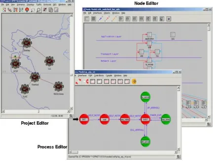
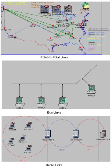
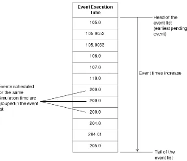
(10) LIST OF FIGURES Figure 1.1 An Example of Multihop Wireless Network ........................................ 4 Figure 2.1 Cross-Layer Framework and interaction among layers (Zhang & Zhang, 2008) ................................................................................................ 17 Figure 3.1 IEEE802.11 LAN topology ................................................................ 22 Figure 3.2 IEEE802.11a PPDU............................................................................ 27 Figure 3.3 IEEE802.11b PPDU (IEEE LAN/MAN Standards Committee, 1999) ...................................................................................................................... 29 Figure 3.4 Beacons and Contention Free Periods ................................................ 31 Figure 3.5 Backoff Mechanism in DCF ............................................................... 32 Figure 3.6 Polling Mechanism in PCF................................................................. 34 Figure 3.7 Generation of CAPs during the CP .................................................... 37 Figure 3.8 Transimission opportunity in HCF ..................................................... 37 Figure 3.9 MAC frame Format ............................................................................ 39 Figure 3.10 Frame Control Field ......................................................................... 40 Figure 4.1 Graphical Editors for Network, Node and Process Models ............... 49 Figure 4.2 Network Models with Point-to-Point, Bus and Radio Links .............. 50 Figure 4.3 A Hierarchical Network with Two Levels of Subnetworking ............ 51 Figure 4.4 Node Model Employing Packet Streams, Statistic Wires .................. 53 Figure 4.5 State Transition Diagram in the Process Editor .................................. 55 Figure 4.6 Typical Simulation Timeline (OPNET Technologies,Inc., 2010) ....... 58 Figure 4.7 Simulation Event List (OPNET Technologies,Inc., 2010) ................. 59 Figure 4.8 Ad-hoc Network ................................................................................. 63 Figure 4.9 Infrastructure BSS .............................................................................. 63 Figure 4.10 Extended Service Set ........................................................................ 63 Figure 4.11 Wireless Backbone ........................................................................... 64 Figure 4.12 Example of Vectors Data Result Panel ............................................. 65 VI.
(11) Figure 4.13 Example of a Scalar Data Result Panel ............................................ 66 Figure 5.1 The ESS Configuration ....................................................................... 69 Figure 5.2 The Reference Scenario ...................................................................... 70 Figure 5.3 Data Access Definition ....................................................................... 70 Figure 5.4 Email Definition ................................................................................. 71 Figure 5.5 File Transfer Definition ...................................................................... 72 Figure 5.6 File Print Definition ............................................................................ 73 Figure 5.7 Web Browsing Definition ................................................................... 73 Figure 5.8 VoIP Call Definition ........................................................................... 74 Figure 5.9 Video Conferencing Definition .......................................................... 75 Figure 5.10 An Example of Multiple ESSs Scenarios ......................................... 78 Figure 5.11 A Scenario with 4 MAPs per ESS .................................................... 79 Figure 5.12 Scenario with 8 STAs per MAP ....................................................... 80 Figure 5.13 EDCA Parameters Setting ................................................................ 82 Figure 6.1 Global Average Throughput of Scheme 1 Scenarios .......................... 85 Figure 6.2 Global Average Throughput of Scenarios .......................................... 86 Figure 6.3 Global Average Throughput of Scenarios .......................................... 86 Figure 6.4 Global Average Throughput of Scenarios .......................................... 87 Figure 6.5 Global Average Throughput of Scenarios .......................................... 88 Figure 6.6 Global Average Delay of Scheme 1 Scenarios without EDCA .......... 89 Figure 6.7 Global Average Delay of Scheme 1 Scenarios with EDCA ............... 90 Figure 6.8 Global Average Delay of Scenarios .................................................... 91 Figure 6.9 Global Average Delay of Scenarios .................................................... 91 Figure 6.10 Global Average Delay of Scenarios .................................................. 92 Figure 6.11 Global Average Delay of Scenarios .................................................. 93 Figure 6.12 Dropped Data by Scenario................................................................ 94. VII.
(12) LIST OF TABLES Table 1.1 IEEE802.11 Standards(IEEE LAN/MAN Standards Committee, 2010) ........................................................................................................................ 3 Table 3.1 IEEE802.11 Services (IEEE LAN/MAN Standards Committee, 1999) ...................................................................................................................... 24 Table 3.2 IEEE802.11a Data Rates (IEEE LAN/MAN Standards Committee, 1999) ............................................................................................................ 28 Table 3.3 IEEE802.11g Options (IEEE LAN/MAN Standards Committee, 2003) ...................................................................................................................... 30 Table 3.4 Values for the Duration/ID Field .......................................................... 41 Table 3.5 Information Contained in the Different Address Fields ....................... 42 Table 3.6 QoS Control Field ................................................................................ 43 Table 5.1 Profile Definition ................................................................................. 77 Table 5.2 Mobiles Variations (Scheme 1) ............................................................ 78 Table 5.3Mobiles Variations (Scheme 2) ............................................................. 79 Table 5.4 Mobiles Variations (Scheme 3) ............................................................ 80 Table 5.5 Profiles Distribution ............................................................................. 81. VIII.
(13) LIST OF ABBREVIATIONS AC. Access Category. ACK. Acknowledgment. AIFS. Arbitration Interframe Space. AIFSN. Arbitration Interframe Space Number. AP. Access Point. BSS. Basic Service Set. BSSID. Basic Service Set Identification. CA. Collision Avoidance. CCA. Clear Channel Assessment. CD. Collision Detection. CRC. Cyclic Redundancy Code. CSMA/CA. Carrier Sense Multiple Access with Collision Avoidance. CTS. Clear To Send. CW. Contention Window. DA. Destination Address. DCF. Distributed Coordination Function. DIFS. Distributed (Coordination Function) Interframe Space. DS. Distribution System. DSSS. Direct Sequence Spread Spectrum. EDCA. Enhanced Distributed Channel Access. EDCF. Enhanced Distributed Channel Function. EIFS. Extended Interframe Space. ERP. Extended Rate PHY. ESS. Extended Service Set. FCS. Frame Check Sequence. FHSS. Frequency Hopping Spread Spectrum IX.
(14) FTP. File Transfer Protocol. HCCA. HCF Controlled Channel Access. HCF. Hybrid Coordination Function. HTTP. Hyper Text Transfer Protocol. IBSS. Independent BSS. IFS. Interframe Space. IP. Internet Protocol. ISM. Industrial, Scientific and Medical frequency band. LAN. Local Area Network. LLC. Logical Link Control. MAC. Medium Access Control. MAP. Mesh Access Point. MIMO. Multiple Input Multiple Output. MPDU. MAC Protocol Data Unit. MSDU. MAC Service Data Unit. MWN. Multihop Wireless Network. NAV. Network Allocation Vector. NLOS. Non-line-of-sight. NRTM. Non Real-Time Maximum. NRTC. Non Real-Time Centric. NRT. Non Real-Time. OFDM. Orthogonal Frequency Division Multiplexing. PBCC. Packet Binary Convolutional Coding. PCF. Point Coordination Function. PHY. Physical Layer. PINC. Pairwise Intersession Network Coding. PLC. Power Line Communications. PLCP. Physical Layer Convergence Procedure X.
(15) PPDU. PLCP Protocol Data Unit. PSDU. PLCP Service Data Unit. QoS. Quality of Service. RT. Real-Time. RTC. Real-Time Centric. RTM. Real-Time Maximum. RA. Receiver Address or Receiving Station Address. RTS. Request to Send. SA. Source Address. SIFS. Short Interframe Space. STA. Station. TA. Transmitter Address or Transmitting Station Address. TCP. Transmission Control Protocol. TXOP. Transmission Opportunity. TGs. 802.11s Task Group. UP. User Priority. VoIP. Voice over Internet Protocol. WDS. Wireless Distribution System. WiFi. Wireless Fidelity. WiMAX. Worldwide Interoperability for Microwave Access. WLAN. Wireless Local Area Network. WM. Wireless Medium. XI.
(16) CHAPTER 1. INTRODUCTION. Chapter 1 commences with an introduction to the background information including a brief history of wireless access technology. The advantage of multihop wireless networks in some particular situations is presented along with some technical limitations in this field. A short overview of the work is then provided, presenting the aims and methodology of the work. At the end, the chapter provides an outline of the thesis.. 1.1. Background. As a senior futurist Thomas Frey predicted in 2006, ―The world of wires has already begun its long descent into oblivion as wireless technology improves to the point where wires become obsolete‖ (Frey, 2006). Although fibre optics has overwhelming advantages in bandwidth and transmission loss, the cost in installation and maintenance, especially for rural areas, limit their applications in access network services. Furthermore, the increasing demand for having the ability to communicate wherever and whenever has lead to an inevitable trend in wireless access.. Regarding the current state of wireless technology applications, wireless connectivity became virtually universal, to a great extent, because of the efforts of the Wireless Fidelity Alliance (WiFi) certification program, which has been the single most important factor for being able to use wireless adapters or embedded chips universally. Today, personal computers, PDAs and telephones, almost every form of consumer electronics without exception, support WiFi connectivity getting access to the Internet via wireless access networks. As a commonly-used wireless access mode, WiFi technology which is built on IEEE802.11 standards has been developed for the last 1.
(17) two decades.. Since first released in 1997, the IEEE802.11 standards have addressed the Physical (PHY) layer and Media Access Control (MAC) layer standards separately. The original PHY standard provides data rates of 1-2 Mbps and three fundamentally different mechanisms of operation, namely, Infrared, 2.4 GHz Frequency Hopping Spread Spectrum (FHSS), and 2.4 GHz Direct Sequence Spread Spectrum (DSSS). Since wireless stations do not have the capability of detecting collisions, the MAC employs an access method that made every effort to avoid collisions, which is known as Carrier Sense Multiple Access with Collision Avoidance (CSMA/CA). In Chapter 3, we will take an in-depth investigation on how the PHY and MAC standard support the operation of wireless networks.. Following the deployment of the standards, several amendments were introduced, trying to compensate for all the drawbacks it had, compared to wired networks: less secure, less reliable, or less throughput. These amendments included the definition of the new physical layer specifications (IEEE802.11a/b/g) to enable higher data rate and throughputs (IEEE802.11n), to increase security (IEEE802.11i), to enable its usage in countries or areas with different spectrum regulation (IEEE802.11d/h/j), or to form a unified network of mesh topology composed of multiple WLAN cells (IEEE802.11s), as listed in Table 1.1. 2.
(18) Table 1.1 IEEE802.11 Standards(IEEE LAN/MAN Standards Committee, 2010) standard. Specification. 802.11. The original standard: 1/2 Mbps, 2.4GHz RF and IR standard (1997). 802.11a. New physical layer, 54 Mbps, 5GHz (1999). 802.11b. New physical layer, 11 Mbps,2.4GHz (1999). 802.11d. Deals with issues related to regulatory differences in various countries (2001). 802.11g. New physical layer, 54 Mbps, 2.4GHz, compatible with 802.11b (2003). 802.11h. Spectrum managed 802.11a (for Europe) (2004) Provides a stronger encryption than WEP and other security enhancements. 802.11i (2004) 802.11j. Extensions for Japan (2004) New Media Access Control layer, to enable Quality of Service Support. 802.11e (2005) Defines the information that should be provided to higher layers, in order to 802.11k facilitate the management and maintenance of a WLAN (2008) 802.11n. Enhancements for higher throughput (2009). 802.11s. Mesh networking (in process). Most of the currently deployed wireless networks operate in infrastructure mode, which rely upon wireless links between wired infrastructure devices (access points) and end user (mobile stations), such as the cellular mobile networks (GSM, CDMA, etc.). However, cost-effective deployment of infrastructure-based solutions is desired in order to meet economic feasibility criteria when emerging requirement for getting access to Internet in a tolerable data rate. In the circumstances, it could be appealing for interconnect access points (APs) via wireless, instead of any physical wired connection to the core network.. The demand and constraints on currently deployed wireless networks outlined above 3.
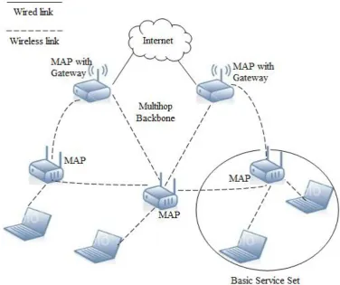
(19) lead to a multihop mesh architecture, where APs become Mesh Access Points (MAPs) able to deliver traffic from source to destination by means of multihop relaying. In this architecture, some MAPs might operate as a portal or gateway to allow access to the Internet, as depicted in Figure 1.1.. Figure 1.1 An Example of Multihop Wireless Network. The above architecture inherits the characteristics of a multihop wireless network (MWN), which can extend the network coverage using variable wireless access technology. The literature, which contains significant research in the field of MWN, will be reviewed in Chapter 2.. 1.2. Objectives of the Study. MWN is, more than a promising technology, now considered as a fundamental 4.
(20) instrument to enable a ubiquitous wireless Internet. Nevertheless, there is still a number of challenging research topics at all protocol layers level that need to be addressed, in order to take advantage of all mesh network potentialities. Among them is the identification of the relationship between network capacity and other factors, such as: network architecture, network topology, traffic pattern, network node density, number of channels used for each node, transmission power level and node mobility (Akyildiz, Wang, & Wang, 2005).. Although the increasing importance of mesh networks and the great number of foreseen applications has driven them to become a hot topic in wireless communications research worldwide, there are still many challenges to be tackled, both on the theoretical and practical sides, for understanding performance limits and devising design principles for infrastructure-based MWNs, for both narrowband and wideband application. Especially, the combination of wireless forwarding and routing protocols allows the establishment of all wireless end-to-end routes among communicating devices placed far away from each other, which could not exist if only standard IEEE802.11 networks were used. Taking this observation into account, the present study aims at evaluating the impact of several parameters into multihop wireless networks capacity and performance in the scope of IEEE802.11 standards.. 1.3. Research Approach. The approach used for achieving the above objectives can be divided into four stages.. Firstly, an in-depth review of the current literature published in the area of MWNs was carried out. This was significant for identifying the trends and issues, and defining the scope of the study. Besides, the study on wireless access technology based on IEEE802.11 was necessary for the operational part of the present study. It could be considered as the theoretical foundation to the following stages. 5.
(21) Secondly, a model of MWN was developed followed by scenarios configurations and several degrees of variations. Since the goal was merely to study the performance of IEEE802.11 based MWNs, the networks provided data rate up to 11 Mbps using DSSS with 2.4 GHz range for the reference scenario. To see how the real-time demand of the applications would affect the network performance, six combinations of commonly-used applications (Data Access, Email, File Transfer, File Print, Web Browsing, Voice over IP Call and Video Conferencing) were imported into the initial model. On the other hand, the variations of the mobiles number and system parameters were taken into consideration in the model.. Thirdly, the study was led to a scenario-based simulation, implemented using the methodology of Discrete Event Simulation (DES), which managed a system as a chronological sequence of event. Limited by the topic, this thesis would not take deep investigation in developing simulator based on this method, but directly chose an appropriate simulation tool OPNET. The basics of OPNET is presented later in Chapter 4.. The fourth stage of the study was to make comparisons and analysis of the results gathered from the simulations in the previous stage. The global performance of the scenarios in terms of throughput, average delay and dropped data was analyzed in groups. From the comparison of various scenarios, we were able to know that how the number and distribution of users, real-time applications and EDCA mechanism affect the global capacity of a MWN.. 1.4. Thesis Outline. The first chapter introduces IEEE802.11 standard and multihop wireless network architecture. The study objectives and approach are also discussed in this chapter. 6.
(22) Chapter 2 provides an in-depth discussion on the current state of Multihop Wireless Networks. The literatures on the characteristics, open issues and research trends are reviewed in this field. Related works on performance evaluation of MWNs are then presented at the end of this chapter.. In Chapter 3, wireless technology based on IEEE 802.11 standards is introduced, following by a description and classification of services. Furthermore, the physical layer specifications and medium access control relevant to the study are discussed.. Chapter 4 starts from a comparison of simulators in communication networks. The remaining of the chapter is dedicated to the description of the used simulation tool, OPNET Modeler, and to the detailed presentation of the simulation model and its implementation.. In Chapter 5, the simulation scenarios are described based on the reference scenario. The variations of user number, profiles and EDCA parameters are introduced in detail.. Chapter 6 presents the analysis of results obtained from the OPNET modeler simulations. The global throughput, delay and dropped data gathered from 168 scenario simulations are compared respectively.. Finally, Chapter 7 presents the conclusion and discussion on the potential directions for future study in the area of the topic.. 7.
(23) CHAPTER 2 REVIEW OF LITERATURE ON MULTIHOP WIRELESS NETWORKS This chapter provides a literature review of previous research and industry work undertaken in the field of multihop wireless networks, following by an in-depth discussion on open issues, research trends and outcomes.. 2.1. Introduction to Multihop Wireless Networks. As various wireless networks evolve into a new development era to provide low-cost, ubiquitous broadband Internet access, Multihop Wireless Networking (MWN) has emerged as a promising technology. In MWNs, nodes are comprised of mesh routers and mesh clients (Akyildiz, Wang, & Wang, 2005), which operate not only as hosts but also as routers, forwarding packets on behalf of other nodes that may not be within direct wireless transmission range of their destinations.. Compared to the connection between mobile clients and access points in a traditional wireless LAN, a MWN consists of access routers communicating with each other wirelessly, potentially over multiple hops, where a small fraction of those access router are wired to the Internet and serve as Internet gateways for the rest of the network (Marina & Das, 2005).. The architecture of a typical MWN is similar to the example illustrated in Figure 1.1. The network is formed by a collection of wireless access points (routers, Internet gateways, etc.) and terminal users (static or mobile stations). It depends on some form of wireless communication between the nodes, which are in accordance with the 8.
(24) IEEE802.11 standard in the present study. As mentioned before, other technologies like Zigbee, ultra-wideband (UWB) and WiMAX have also been utilized to form WMNs respectively or hybridizably (Wang, 2008). Because MWNs based on WiFi technology have been the most commercially successful to date, the most common sense reflects that multihop wireless mesh networks are implemented over a wireless LAN based on IEEE802.11 standards.. The primary objective to develop MWNs is to extend the coverage range of current wireless networks without sacrificing the channel capacity. On the other hand, providing non-line-of-sight (NLOS) connectivity among the users without direct line-of-sight (LOS) links is another purpose of building MWNs. Due to these features, the characteristics of MWNs are summarized as below: Multi-hopping Compared to other wireless networks, multihop wireless links collectively exhibit graceful drop behavior: as the offered load increases, the link contention drop probability also increases, but saturates eventually (Fu, Zerfos, Luo, Lu, Zhang, & Cerla, 2003).. In 2004, Qiu, et al. offered an impelling support for multihop approach by optimizing the placement of access points. They developed algorithms to make informed placement decisions based on neighborhood layouts, user demands, and wireless link characteristics (Qiu, Chandra, Jain, & Mahdian, 2004).. Multi-hopping is indispensable for MWNs, as it can highly increase throughput without sacrificing effective radio range via shorter link distances (Fu, Zerfos, Luo, Lu, Zhang, & Cerla, 2003), less interference between the nodes (Jein, Padhye, Padmanabhan, & Qiu, 2005), and more efficient frequency reuse (Ramchandran, Belding, Almeroth, & Buddhikot, 2006). 9.
(25) Support for ad hoc networking, and capability of self-forming, self-healing, and self-organization MWNs can efficiently enhance network performance, largely because of flexible network architecture, easy deployment and configuration (Marina & Das, 2005), fault tolerance (Qiu, Chandra, Jain, & Mahdian, 2004), and mesh connectivity (Garetto, Shi, & Knightly, 2005). Also due to the features above, MWNs have low upfront investment requirement, and the network can grow gradually as demanded (Wang, 2008).. Mobility Access points (i.e. routers) usually have minimal mobility, while terminal users can be static, nomadic or mobile nodes. This offers another option for the integration of data communication networks (i.e. Internet) and telecommunication system (i.e. CDMA).. Dependence of power-consumption constraints on the type of nodes Because of the mobility, access points usually do not have strict constraints on power consumption. In contrast, users may require power efficient protocols. Sensor network designers need the ability to obtain accurate and dependable power consumption figures to tune their applications before deployment in real environments. Apart from aggregate power consumption over time, the pattern of power load is important to consider, as this affects the ability of the power source to deliver adequate energy over time (Shnayder, Hempstead, Chen, Allen, & Welsh, 2004).. Compatibility and interoperability with existing wireless networks As MWNs are developed from existing wireless technologies, which are widely 10.
(26) deployed in cellular networks and data communications, MWNs inevitably need to be inter-operable with other wireless networks such as UMTS, ZigBee, etc.. 2.2. Open Issues and Research Trends. Despite the fact that there is a vast range (or flavors) of multihop wireless networks that have been studied, there exist many open issues. This section attempts to summarize some of these issues, which may be considered as potential research themes in the further study.. 2.2.1 Protocols for Network Management Many management functions are needed to maintain the appropriate operation of MWNs (Akyildiz, Wang, & Wang, 2005).. Mobility management There are two components in mobility management: location management and handoff (also referred to as handover in the literature) management (Yu, Wong, Song, Leung, & Chan, 2010). In MWNs, location management enables the network to deliver massages to mobile users by tracking their locations between connections, while handoff management maintains service continuity by enabling a mobile terminal to keep connected when it moves form one access point region to another.. Although the mobility management schemes developed for other networks including cellular, ad hoc and mobile IP networks could be useful for MWNs, these schemes cannot perform well for MWNs due to the specific features of MWNs. These schemes assume that the fixed networking paths are stable and the hierarchies can be deterministically created following the network layout at deployment. In such networks, MAPs can be placed at the root nodes in the tree 11.
(27) hierarchy and sub-domains for the MAPs are formed with the children under the root nodes. These assumptions do not hold true for WMNs which usually have an unplanned graph topology and where the wireless links are unstable and exhibit varying latencies. In 2008, Wu et al. presented that Hierarchical mobility management scheme HMIP is applicable on MWNs and is able to give a close to optimal packet loss rate and handoff latency.. Location service is a desired feature in MWNs. A novel mobility management mechanism Wireless Mesh Mobility Management (WMM) for MWNs was proposed in 2008 (Huang, Lin, & Gan, 2008). WMM adopts the location cache approach, where the mobile nodes cache the IP address of user’s serving MAP (known as user’s location information) while routing the data for the user.. Handoff management is closely related to multiple layers of network protocols. The development of multi-layer handoff management schemes as shown in (Yu, Wong, Song, Leung, & Chan, 2010) is a challenging topic.. Power management Usually MAPs do not have a constraint on power consumption as individual nodes. However, power management appears to be significant in the scope of a MWN, as power management schemes provide every level of energy savings at each layer of network protocol stack (Klues, 2006).. The various techniques are used to conserve energy form the application layer all the way down to the physical layer. At the application layer, it is worth to exploring techniques that specifically deal with reducing the power consumed while running the common applications such as database operations and video processing (Jones, Sivalingam, Agraval, & Chen, 2001). The TCP-Probing 12.
(28) (Tsaoussidis & Badr, 2000) and Wave and Wait Protocols (Zhang & Tsaoussidis, 2001) have been developed to guarantee end-to-end data delivery with high throughput and low power consumption. The techniques existing at the network layer are concerned with performing power efficient routing through a multihop network either backbone based, topology control based, or a hybrid of both (Karl, 2003). The schemes at data link layer are used to reduce the number of packet errors at a receiving node. In most cases, lots of power is wasted listening on the radio channel while there is nothing there to receive, and the MAC layer power saving is deployed to avoid it. Generally, proper hardware design techniques at physical layer allow one to decrease the level of parasitic leak currents in devices (Jacome & Catthoor, 2003).. Ongoing research has been providing innovative solutions including power aware routing, sleep scheduling, energy harvesting, etc. Although the protocols are similar in terms of principle, the power savings achieved using each of them varies from system to system and application to application. One technique is not better than the other in this sense, so efforts are being made to define exactly when each type should be used.. Network monitoring From a network management perspective, monitoring offers several benefits to the robust operation of wireless networks, including (i) providing statistics to pinpoint the sources of network failure, (ii) verifying if the strategies adopted by protocols, applications or middleware perform well, and (iii) locating potential bottlenecks so as to redimension the network (Sailhan, et al., 2007).. The monitoring of MWNs, however is challenging. The rapid pace of development of wireless technologies brings a large amount of proprietary 13.
(29) solutions with little standardization. Consequently, operating and maintaining a set of such devices becomes cumbersome and scales poorly with increasing network size. To deal with the above limitations, a scalable framework VISUM was presented (Ho, Ramachandran, Almeroth, & Belding-Royer, 2004). Using a modular architecture, VISUM collects MAC layer information from wireless network infrastructure components to provide real time views of network status. This implementation developed in JAVA has been successfully tested in a real-time environment for a month.. Due to the inherent uncertainty in the wireless medium, network administrators require a comprehensive set of data and metrics to deal with them. Besides, the method of storing accumulated information must be considered carefully, allowing efficient data retrieval. To this end, a multi-tiered monitoring framework MeshMon was proposed (Raghavendra, Acharya, Beling, & Almeroth, 2009). MeshMon dynamically controls the granularity of data collection based on observed events in the network, thereby achieving significant bandwidth savings and enabling real-time automated management. The evaluation of MeshMon on a real testbed shows that it can diagnose a majority (87%) of network faults with a 66% savings in bandwidth required for network monitoring.. A number of monitoring protocols have been designed and implemented, however, the extensibility of these schemes needs to be achieved for the purposes of collecting information form newly developed devices. In addition, how to quickly determine network topology is also an open issue.. 2.2.2 Security Due to the unique characteristics of MWNs, they are highly vulnerable to security attacks compared to wired networks. Designing a robust security mechanism for 14.
(30) MWNs is a challenging task. The security can be provided in various layers of protocol stack. Current security approaches may be effective against a particular attack in a specific protocol layer, but they lack a comprehensive mechanism to prevent or counter attacks in different protocol layers. The following issues pose difficulty in providing security in MWNs. Shared radio channel Because the wireless links between the nodes in MWNs are broadcast in nature, a malicious node could easily obtain data being transmitted if it is placed in the transmission range of MAPs. An attacker may paralyze nodes in its neighborhood by sending CTS frames periodically, setting the ―Duration‖ field of each frame to at least the interval between such frames (Hu & Rerrig, 2005).. Lack of association In MWNs, the MAPs form a fixed mesh topology for the mobile users. Hence, the clients can join and leave the network at any time via MAPs. If no proper authentication mechanism is provided for association of nodes with MWNs, an intruder would be able to join the network quite easily and carry out attacks may sneak into the network by misusing cryptographic primitives (Borisov, Goldberg, & Wagner, 2001).. Limited resource availability Normally, the mesh clients are limited in resources such as bandwidth, battery power, computational power, etc. Therefore, it is difficult to implement complex cryptography-based mechanisms at the client nodes. As MAPs are resource-rich in terms of battery power and computational power, security mechanisms can be implemented at MAPs. Due to wireless connectivity between MAPs, they also have bandwidth constraints. Consequently, the communication overhead incurred by the security mechanism should be minimal (Zhang, Zheng, & Hu, 2008). 15.
(31) The key management is one of the most important tasks for network security (Akyildiz, Wang, & Wang, 2005). However, the key management for MWNs becomes much more difficult, because there is no central authority, trusted third party or server to manage security keys. To enhance security, two strategies also need to be adopted: either to embed security mechanism into network protocols such as secure routing and MAC protocols; or to develop security monitoring and response systems to detect attacks, monitor service disruption and respond quickly to attacks. However security attacks in a network may come simultaneously from different protocol layers. Thus, a multi-protocol layer security scheme is desired for network protocols. How to design and implement a practical security monitoring system, including cross-layer secure network protocols and various intrusion detection algorithms, is a challenging research topic.. 2.2.3 Cross-Layer Design There are many studies that discuss performance improvement of MWNs in recent years from the single-layer point of view. Because of the direct coupling among different layer, the traditional layered design is not sufficient for MWNs (Zhang & Zhang, 2008). All the controls in different layers potentially have mutual impact, and it is necessary to consider all the controls across different layers jointly to optimize the overall performance. Such interactions demand a cross-layer design among these layers. Figure 2.1 illustrates the cross-layer framework and the potential interaction among layers. In this design, interdependencies between layers are characterized and exploited by adapting to information exchanged between layers and building the appropriate amount of robustness into each layer. For instance, scheduling and channel management in the MAC layer can avoid links experiencing deep fades and resending messages.. 16.
(32) Figure 2.1 Cross-Layer Framework and interaction among layers (Zhang & Zhang, 2008) Although it is reasonable to believe that cross-layer optimization will continue to be one of the most important tasks in protocol design for MWNs, critical issues must be considered for cross-layer design. The method of optimization decomposition, which was proposed in (Akyildiz & Wang, Cross-Layer Design in Wireless Mesh Networks, 2008), took fully consideration of risks due to loss of protocol-layer abstraction, incompatibility with existing protocols, unforeseen impact on the future design of the network, and difficulty in maintenance and management.. Unlike building around the existing routing concept which focuses on cross-layer design that considers the corresponding network utility maximization problem, network coding allows intermediate nodes to perform coding operations in additions to pure packet forwarding. In (Khreishah, Wang, & Shhroff, 2009), they proposed a jointly optimal coding, scheduling, and rate-control scheme based on pairwise intersession network coding (PINC). Numerical experiments had proven that in a MWN, the throughput advantage of PINC could be achieved without sacrificing the 17.
(33) stability conditions. Moreover, PINC had minimal impact on the optimal rate-control and scheduling as the only new component necessary for scheduling PINC traffic is the balance update performed at the receivers.. To date, cross-layer design of MWNs lacks standard on framework and methodology. To further improve the viability of cross-layer design schemes, standardizing the framework is necessary.. 2.3. Performance Evaluations. Considering the flexibility of a MWN, the designers of the networks have to take much attention on network performance trade-offs. Despite of the impact of various factors of a MWN, a lot of works have been done in the last decade on performance evaluations, such as throughput, transmission delay, fairness, etc.. Quite a few performance evaluations have taken place on testbeds or straightly gone with a project implementation. Dated back to December 2006, Technology for All (TFA) and Rice University have partnered to develop and test a MWN for low-income communities in Houston. In this project, a hardware platform EPIA VE10000 Mini-ITX Board has been used in the evaluation. On systems running Linux kernel with LocustWorld open-source networking software, the platform met expectation of 1 Mb/sec for commercial connection (Camp, Knightly, & Reed, 2006).. In contrast to network-layer statistics in previous work, Cheng, et al. (2008) evaluated the system performance of application layer video quality in a MWN testbed and provided insights in potential problems and solutions for supporting video streaming. The paper analyzed impacts on video performance, and found that impact of interference was the major source of quality degradation. In the experiment, the tradeoff between video coding rate and the achieved video quality has been studied, 18.
(34) and the conclusion was again that interference in mutihop scenatios significantly worsened the video performance (Cheng, Mohapatra, Lee, & Banerjee, 2008). For evaluating impact of the rate adaptation algorithms on MWNs performance, indoor and outdoor testbeds have been built separately (Ancillotti, Bruno, & Conti, 2008).. Hamidian, et al. (2009) created a testbed for MWNs using the Mesh Connectivity Layer (MCL), which is part of the Microsoft Mesh Toolkit. Three groups of outcomes from experiments on scenarios with FTP/TCP session, VoIP streams and video streams were presented (Hamidian, Palazzi, Chong, Nanarro, Korner, & Gerla, 2009). In addition, another major finding from this paper was that the testbed could be used to evaluate complex and realistic scenarios with more complex interactive applications, such as online games, cooperative multimedia management, and augmented reality services.. In the same year of 2009, FloorNet, a 802.11-based MWN testbed, was presented by Serrano, et al (Serrano, Bernardos, Oliva, Banchs, Soto, & Zink, 2009). The unique characteristics of the false floor constituted strong support for the deployment of MWN testbeds. But it was noticed that nonideal behavior of off-the-shelf hardware existed in i) the impact of the entity generating traffic in the measurements, and ii) the strong interference between non-overlapping channels.. Most of the performance evaluations on MWNs have been based on simulation. As a free open-source simulator, NS-2 became one of the most popular tools in networks performance evaluation. In (Fu, Zerfos, Luo, Lu, Zhang, & Cerla, 2003), the analysis based on NS-2 simulations showed the relationship between throughput and specific topology and flow settings. Using a conflict graph, Jain, et al. (2005) modeled wireless interference in MWNs to evaluate the impact of it on optimal throughput with the assistance of NS-2. Nevertheless, the assumption of packet transmissions in 19.
(35) their simulations is unrealistic (Jein, Padhye, Padmanabhan, & Qiu, 2005). We will present the drawbacks of using NS-2 on performance evaluation in the next chapter.. On the other hand, the performance evaluation of WMNs has been developing in various directions. Some researches focused on different communication protocols rather than IEEE802.11, such as (Han, Jia, & Lin, 2006). But Gambiroza et, al. had objective of studying fairness in MWNs. To implement their target, they performed an extensive set of simulation experiments and then developed and studied a distributed MAC layer fairness algorithm which aimed to achieve the fairness of the reference model without modification to TCP (Gambiroza, Sadeghi, & Knightly, 2004).. Apart from the simulation environment used as above, Ernst and Denko proposed the other two approaches ―Performance Metrics and Simulation Parameters‖ and ―Analysis of the Experimental Results‖ in their paper, which focused on fair scheduling algorithms for MWNs (Ernst & Denko, 2010).. 20.
(36) CHAPTER 3 AN OVERVIEW OF WIRELESS NETWORK STANDARDS Chapter 3 provides a technical overview of IEEE802.11 based wireless networks, particularly of physical layer protocols and medium access control protocols considered appropriate for the present study for identification of parameters and network characteristics.. 3.1. Introduction. Although the multihop mesh architecture could be implemented with all kinds of wireless access technologies, like Zigbee, UWB and WiMAX, only IEEE802.11 standards are deployed in the present study, for the reason mentioned in the objective (see Chapter 1) and the literature review (see Chapter 2).. Wireless networks based on IEEE802.11 standards have fundamental characteristics that make them significantly different from traditional wired LANs. The PHYs used in IEEE802.11 are fundamentally different from wired media. Thus IEEE 802.11 PHYs use a medium that has neither absolute nor readily observable boundaries outside of which STAs with conformant PHY transceivers are known to be unable to receive network frames. Although they are unprotected from other signals that may be sharing the medium which is significantly less reliable than wired PHYs, wireless PHYs have time-varying and asymmetric propagation properties and dynamic topologies (IEEE LAN/MAN Standards Committee, 2007).. 21.
(37) 3.1.1 IEEE802.11 LAN Topology The concept of service set is the basis of the different types of wireless LAN topologies. A service set is a grouping of devices that access the network by broadcasting a signal across a wireless radio frequency (RF) carrier. The basic service set (BSS) is the basic building block of an IEEE 802.11 LAN. Figure 3.1 shows two BSSs, each of which has two stations (STAs) that are members of the BSS.. Figure 3.1 IEEE802.11 LAN topology. In a BSS, the service set consists of two entities: the STA and the AP. There can be several stations that communicate with one another via the AP, which acts as a relay station. An AP can also function as a bridge to the outside world, providing a connection to some kind of backbone Distribution System (DS).. The independent BSS (IBSS) is the most basic type of IEEE 802.11 LAN. A minimum IEEE 802.11 LAN may consist of only two STAs. The role of an AP does not exist in an IBSS. Stations communicate directly with one another without the use of an intermediate. This self-contained network is a simple peer-to-peer WLAN, 22.
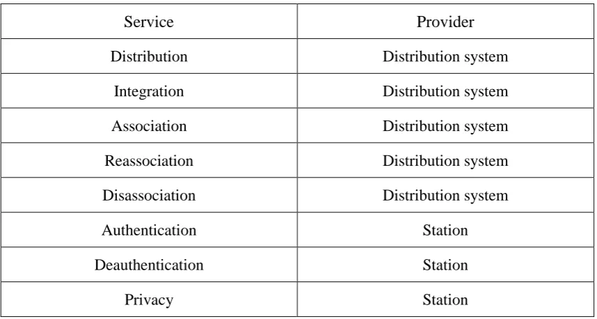
(38) which is also referred to as an ad-hoc network. Typically, an IBSS is small and only lasts enough time until the communication being performed is completed.. The extended service set (ESS) is the most generic topology for a WLAN, consisting of two or more BSSs that are interconnected by a DS. Figure 3.1 shows a simple representation of an ESS, where it is possible to identify a collection of BSSs, grouped via a DS. In this case, if STA4, located in BSS2, wants to send a frame to STA1, it has to send it first to AP2, which acts as the AP of BSS2, being responsible for forwarding the frame to AP1 (the AP of BSS1). Finally, AP1 is able to deliver the frame to its final destination. It is important to note that this process is performed at the MAC level, thus, the ESS appears as a single logical unit to the Logic Link Control (LLC) one. This way, the frame that is exchanged according to the described process between MAC users is known as the MAC Service Data Unit (MSDU). Moreover, the MSDU delivery from the MAC to the upper layer constitutes the basic service of an IEEE802.11 LAN.. 3.1.2 IEEE802.11 Station Services From the above simple description of a frame traversing an ESS, the need of the IEEE802.11 standard to define a set of complementary services for the basic MSDU delivery becomes evident, which are listed in Table 3.1. The provider column indicates who is responsible for the service. Station services are provided among all stations, therefore, being implemented in every 802.11 station, including APs. Distribution services are available among BSSs, by the DS, being implemented only in APs or in another special-purpose device attached to the DS. The first five services are used to support MSDU delivery, which is discussed in section 3.3, while the last three are used to control IEEE 802.11 LAN access and confidentiality.. 23.
(39) Table 3.1 IEEE802.11 Services (IEEE LAN/MAN Standards Committee, 1999) Service. Provider. Distribution. Distribution system. Integration. Distribution system. Association. Distribution system. Reassociation. Distribution system. Disassociation. Distribution system. Authentication. Station. Deauthentication. Station. Privacy. Station. Distribution is the primary service used by stations to send MAC frames to another station located in a different BSS within the same ESS. In the example of Figure 3.1, AP2 uses the distribution service in order to send a frame to STA1. In the case of stations exchanging a frame that are located in the same BSS, the distribution service goes through the single AP of that BSS. The other service that is responsible for the distribution of messages within a DS is integration, which enables transfer of frames between a station on an IEEE 802.11 LAN and another on an IEEE 802.x LAN that is physically connected to the DS.. For a correct operation of the services that are responsible for the transfer of MSDUs among MAC users, some kind of information about the location of the various stations within an ESS is necessary. This requirement is fulfilled by the association, reassociation and disassociation services. The association service establishes an initial association between a station and an AP, by which the AP is able to register the identity and address of the station. The AP can then communicate this information to other APs within the ESS, to facilitate routing and delivery of frames. Association is usually preceded by a probe process that is used by a station to select the most 24.
(40) adequate AP to associate with. Concerning the mobility of stations, when a station moves from a BSS to another, the established association must be transferred to another AP using the reassociation service. The end of an existing association, because a station is either leaving the ESS or shutting down, must be notified using the disassociation service.. In order to provide a minimum level of security, three services are provided: authentication, deauthentication and privacy. Before the association process is accomplished, the station that wants to communicate with another one needs to prove its identity using the authentication service. The standard does not mandate any particular authentication scheme, which can range from a simple handshaking to a public key encryption scheme. The reverse process, when an existing authentication is to be terminated, is performed by the deauthentication service. Another security mechanism, used to prevent messages from being read by a casual eavesdropper, is the privacy service. This service consists of an optional encryption mechanism that takes the content of a data frame and passes it through an encryption algorithm, in both the sending and the receiving stations.. 3.2. IEEE802.11 Physical Layer. In an IEEE802.11 LAN, an underlying physical layer is defined to support all the functions of the MAC layer. Besides this primary function, it is also responsible for other secondary ones, such as assessing the state of the wireless medium and reporting it to the MAC.. 3.2.1 The Various Physical Layers The basic function of the 802.11 PHY layer is to provide wireless transmission mechanisms for the MAC layer. As described previous, the PHY layer comprises two sublayers: the PLCP and the PMD. While the former is responsible for mapping 25.
(41) MPDUs frames, coming from the upper MAC layer, onto an appropriate frame format, the latter provides adequate methods for transmitting and receiving user data through a wireless medium. The PLCP sublayer can also be seen as an interface between MAC and PMD, defining a set of primitives that enable communication between the two adjacent layers. These primitives provide the interface for transfer of data between the MAC and the PMD. Moreover, on transmission, there are primitives that enable the MAC to tell PMD when to initiate transmission. On reception, PLCP primitives indicate the start of an incoming transmission from another station to the MAC.. The IEEE 802.11 original standard has defined the MAC layer and three PHY layer specifications, which are based on the following methods: Infrared at 1 Mbps and 2 Mbps, operating at wavelength between 850~950 nm. Frequency Hopping Spread Spectrum (FHSS) also operating in the 2.4 GHz ISM band, at the same data rates. This technique uses 1 MHz channels and splits the available bandwidth into 79 non-overlapping channels. Direct Sequence Spread Spectrum (DSSS) operating in the 2.4 GHz Industrial, Scientific and Medical (ISM) band, at data rates of 1 Mbps and 2 Mbps. DSSS WLANs use 22 MHz channels that allow three non-overlapping channels in the 2.4 to 2.483 GHz range.. To overcome some limitations of the original PHY layer, several PHY specifications have been standardized: IEEE 802.11a, 802.11b and 802.11g.. 3.2.2 IEEE802.11a IEEE 802.11a operates in the 5 GHz frequency band (IEEE LAN/MAN Standards Committee, 1999). It defines a set of 20 MHz channels within the Universal 26.
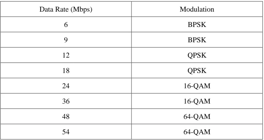
(42) Networking Information Infrastructure (UNII) band, which is divided into three parts: the UNII-1 band (5.15 to 5.25 GHz), intended for indoor use; the UNII-2 (5.25 to 5.35 GHz), to be used for either indoor or outdoor; and the UNII-3 (5.725 to 5.825 GHz), exclusively for outdoor use. The standard provides mandatory data rates up to 24 Mbps (6, 9, 12, 18 and 24 Mbps) and some optional rates up to 54 Mbps (36, 48 and 54 Mbps). 802.11a does not use a spread spectrum scheme; instead, it uses Orthogonal Frequency Division Multiplexing (OFDM), which uses multiple subcarriers for sending bits on each one.. The PLCP sublayer provides all the framing and signalling needed for PMD operations. It takes the MPDUs coming from the upper MAC layer and adds some additional information, forming a PLCP PDU (PPDU). Figure 3.2 illustrates the PPDU frame format.. Figure 3.2 IEEE802.11a PPDU. The PLCP preamble enables the receiver to acquire an incoming signal and to synchronize the demodulator. The preamble and signal fields are transmitted at the minimum data rate, i.e., 6 Mbps. Subsequently, follows the transmission of the data field at the rate specified in the rate subfield. Prior to transmission, the data field has to pass through a scrambling process. Besides the MPDU, the data field consists of the following subfields: 27.
(43) Service: used to synchronize the scrambler at the receiver. Tail: used for encoding purposes. Pad: used to provide the remaining bits to make the data field a multiple of the number of bits in an OFDM symbol.. Together with OFDM, the PMD sublayer supports several modulation and coding alternatives. Each carrier is divided in up to 48 subcarriers that are modulated using BPSK, QPSK, 16-QAM or 64-QAM. Table 3.2 shows the correspondence between available data rates and used modulation.. Table 3.2 IEEE802.11a Data Rates (IEEE LAN/MAN Standards Committee, 1999) Data Rate (Mbps). Modulation. 6. BPSK. 9. BPSK. 12. QPSK. 18. QPSK. 24. 16-QAM. 36. 16-QAM. 48. 64-QAM. 54. 64-QAM. 3.2.3 IEEE802.11b IEEE 802.11b is an extension of the original DSSS scheme, providing additional data rates of 5.5 and 11 Mbps in the same ISM band (IEEE LAN/MAN Standards Committee, 1999). Channel bandwidth is also 22 MHz, providing the same 3 non-overlapping channels. A chipping code, or pseudonoise sequence, is the basis of DSSS, which is used to spread the data rate of the signal. The original 802.11 DSSS 28.
(44) uses an 11-chip Barker sequence.. The preamble field represented in Figure 3.3 has two subfields: the sync one, to synchronise the demodulator, and the Start-of-Frame Delimiter (SFD). The header follows the preamble, consisting of the following subfields: Signal: provides the data rate at which the MPDU field is transmitted. Service: indicates which encoder is used, among other functions. Length: indicates the number of microseconds that are necessary to transmit the. MPDU field. CRC: error detection code.. Figure 3.3 IEEE802.11b PPDU (IEEE LAN/MAN Standards Committee, 1999). To achieve the lower data rates, the PMD 802.11b sublayer employs the same techniques as the original standard, which is DSSS using an 11-chip Barker sequence with DBPSK modulation, for 1 Mbps, and with DQPSK modulation for 2 Mbps. To achieve the higher data rates with the same chipping rate and using the same bandwidth, a more complex modulation scheme is needed. The mandatory scheme is a Complementary Code Keying (CCK) one, which takes 8 bits at a 1.375 MHz rate. Six of these bits are mapped onto one of 64 codes sequences. The output of the mapping and the remaining two bits are applied to the input of a DQPSK modulator. Additionally to CCK, the standard also provides an optional modulation scheme, 29.
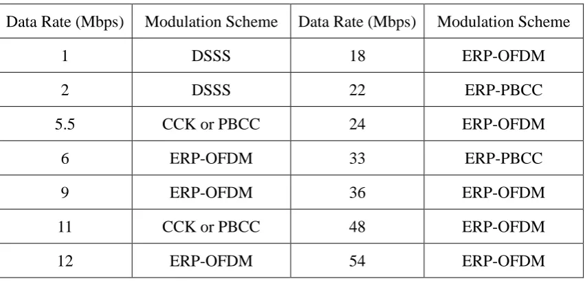
(45) named Packet Binary Convolutional Coding (PBCC), which provides a more efficient transmission at the cost of increased computation requirements.. 3.2.4 IEEE802.11g The IEEE 802.11g standard introduces an Extended Rate Physical (ERP) layer to support higher data rates in the 2.4 GHz ISM band (IEEE LAN/MAN Standards Committee, 2003). The standard guarantees interoperability with the older 802.11b system, providing the same modulation and framing schemes for the lower data rates of 1, 2, 5.5 and 11 Mbps. Additionally, the 802.11g also provides a wide range of data rates: 6, 12 and 24 Mbps that are mandatory, and 9, 18, 36, 48 and 54 Mbps that are optional. To support this additional data rates, a new modulation scheme is defined, referred to as ERP-OFDM. It is also possible to optionally use a DSSS-OFDM scheme to support the same data rates and an ERP-PBCC scheme to support 22 and 33 Mbps. Table 3.3 summarizes some of the options in terms of data rates and modulation schemes.. Table 3.3 IEEE802.11g Options (IEEE LAN/MAN Standards Committee, 2003) Data Rate (Mbps). Modulation Scheme. Data Rate (Mbps). Modulation Scheme. 1. DSSS. 18. ERP-OFDM. 2. DSSS. 22. ERP-PBCC. 5.5. CCK or PBCC. 24. ERP-OFDM. 6. ERP-OFDM. 33. ERP-PBCC. 9. ERP-OFDM. 36. ERP-OFDM. 11. CCK or PBCC. 48. ERP-OFDM. 12. ERP-OFDM. 54. ERP-OFDM. Five PPDU formats are provided, differing in the way the preamble is defined; three are mandatory preambles (a long, a short, and an ERP-OFDM one), the remaining two, which are optional, being the long and short DSSS-OFDM preambles. 30.
(46) 3.3. IEEE802.11 Medium Access Control. 3.3.1 MAC Data Services MAC data services provide peer LLC entities with the ability to exchange MSDUs. To support this service, the local MAC uses the underlying PHY-level services to transport an MSDU to a peer MAC entity, where it will be delivered to the peer LLC. This frame exchange between MAC entities requires a mechanism to access the common medium in a WLAN.. The IEEE 802.11 MAC defines two transmission modes for data packets: the Distributed. Coordination. Function. (DCF). based. on. CSMA/CA. and. the. contention-free Point Coordination Function (PCF) where the Access Point controls all transmissions based on a polling mechanism. The DCF and PCF modes are time multiplexed in a superframe, which is formed by a PCF contention-free period (CFP) followed by a DCF contention period (CP), positioned at regular intervals, as shown in Figure 3.4.. Figure 3.4 Beacons and Contention Free Periods. The AP transmits beacon frames periodically in order to deliver management information to terminals. The boundaries between CFPs and CPs are marked by 31.
(47) beacons carrying the Delivery Traffic Indication Message (DTIM). Terminals can use the information present in the beacons in order to associate with the AP, which is performed during the CP. This association is mandatory if the terminal needs to have its transmissions scheduled by the PCF, which is usually required for QoS sensitive data.. Packet priorities are implemented defining three different length Interframe Spaces (IFSs): SIFS (Short IFS): is the shortest IFS, used for all immediate response actions, as the ASK transmission. PIFS (Point coordination function IFS): is a middle-length IFS, after whose interval expires, any PCF mode frames can be transmitted. DIFS (Distributed coordination function IFS): is the longest IFS, used in the DCF operation as a minimum delay for frames contending the medium according to the CSMA back off mechanism.. The DCF mode is based on a CSMA/CA mechanism. The access control scheme is shown in Figure 3.5.. Figure 3.5 Backoff Mechanism in DCF. 32.
(48) A terminal that intends to transmit and senses the channel busy waits for the end of the ongoing transmission, then waits for a time period of DIFS length, and then randomly selects a time slot within the backoff window. The backoff length is calculated as follows:. Backoff _length = Random(0, CW) × aSlotTime. (1). The slot duration, aSlotTime, depends on the network round-trip propagation delay. The number of backoff slots is derived from a uniform distribution over the interval (0, CW), where the contention window (CW) parameter ranges from a minimum value of aCWmin up to a maximum value aCWmax. Initially, the CW parameter is set to aCWmin and can be increased up to 255.. If no other terminal starts transmitting before the intended slot is reached, the transmission of a fragment with maximum size of a Fragmentation Threshold is started. Collisions can only occur in the case that two terminals have selected the same slot. For each unsuccessful transmission the contention window is updated as follows: CW = 22+i − 1. (2). Where i is the number of transmission attempts.. If another terminal has selected an earlier slot, transmission is deferred and its backoff counter is frozen. Then, the terminal waits for the channel to become idle and then waits for the backoff slots remaining from the previous competition. After the successful transmission of the first fragment of a MSDU, the remaining fragments are transmitted sequentially separated by a SIFS interval. Transmission ends when all fragments of the MSDU are transmitted or the maximum dwell time (aMediumOccupancyLimit) expires.. In order to guarantee undisturbed transmission even if hidden terminals are present, 33.
(49) an RTS/CTS mechanism is used. When this mechanism is applied, the contention winner does not transmit the data immediately. Instead it sends an RTS frame to which the receiver answers with a CTS frame. This guarantees, that all terminals in the range of both the sender and the receiver, know that a packet will be transmitted, remaining silent during the entire transmission. Only then the sender transmits the data frames. While the two extra messages present additional overhead, the mechanism is particularly useful in the case of large data frames because the RTS and CTS frames are short.. The PCF mode is based on a polling mechanism controlled by the AP as depicted in Figure 3.6.. Figure 3.6 Polling Mechanism in PCF. During the CFP, the AP polls the terminals registered in its polling list and allows them undisturbed contention-free access to the medium. As already said, in order to become registered in the polling list, the terminals have to associate with the AP during the CP. The maximum duration of a CFP is given by the 802.11 Management Information Base (MIB) variable aCFPMaxDuration, while the frequency is given by the variable aCFPRate.. 34.
(50) During the CFP a frame can be a composite of control and data information. The following combinations are allowed for PCF frames: DATA, CF-ACK, CF-POLL, DATA+CFACK,. DATA+CF_POLL,. DATA+CF-ACK+CF-POLL. and. CF-ACK+CF-POLL. Only the AP has the capability to issue frames with CF-POLL. The terminals can answer with DATA, CF-ACK, DATA+CF-ACK or a NULL frame (the latter is sent when there is no data to transmit and no pending acknowledgement). Each DATA frame cannot be longer that the maximum size aFragmentationThreshold. If the terminal does not answer a polling request within an interval of PIFS, the AP concludes that an uplink frame was lost and may decide to poll the same terminal again.. DCF is the most appropriate in a context where there is no network infrastructure and users must form temporary ad hoc networks to communicate directly between each other. On the other hand, if the objective is to offer a permanent network infrastructure to provide access to the Intranet/Internet with guaranteed QoS bounds, PCF is the best choice.. It can be easily noticed that legacy DCF cannot fulfill the QoS requirements of multimedia applications such as telephony and videoconference, as it does not include prioritization mechanisms. IEEE 802.11 Task Group E elected Virtual DCF (VDCF) as the Enhanced Distributed Coordination Access (EDCA) mechanism to be incorporated in the IEEE 802.11e standard, (IEEE LAN/MAN Standards Committee, 2005). EDCF introduces a prioritization enhancement based on different Access Categories (ACs). One or more User Priorities (UPs) can be assigned to each AC. In this case, each UP within each AC has a different queue, different IFS (Arbitration IFS – AIFS) and contention window parameters. Each AC contends for medium access with only one CSMA instance using the parameters that belong to its lowest UP. This corresponds to the priority of the AC as a whole. 35.
(51) The AIFS length of UP i is set according to the following formula: AIFSi = SIFS + aAIFSi × aSlotTime. (3). The default value for aAIFSi is 2 slots, which makes AIFSi equal to DIFS time as in the legacy DCF. A terminal having several ACs maintains a separate backoff timer for each of those ACs, with each backoff timer independently counting down. The backoff of each AC j is chosen according to a uniform distribution over [0, CWi], where i is the lowest UP of the AC and CWi is the corresponding contention window: Backoffj = Random 0, CWi × aSlotTime. (4). CWi is an integer within the range aCWmini and, optionally, aCWmaxi. Upon collision it is updated using the same generator function as for legacy DCF. When the backoff timer of an AC counts down to zero, the terminal transmits a frame from the queue with highest priority and initiates a transmission opportunity (TXOP), which is a bounded duration time interval in which the station may transmit a sequence of SIFS-separated DATA frame exchanges. Internal conflict between local ACs occurs when the corresponding backoff timers expire at the same time. In that case, the ESTA transmits a frame from the AC of highest priority, and then resets all expired backoff timers. During the TXOP, the terminal can send a burst of DATA frames separated by SIFS in the same way already explained for legacy DCF. The TXOP ends when there are no more frames to be transmitted or when the TXOP maximum duration expires. The default TXOP maximum duration is given by the MIB variable dot11DefaultCPTXOPLimit, but the TXOP limit can be modified the AP in beacons or association response frames.. Besides enhancing DCF, IEEE 802.11e also specifies a new mode of operation named Hybrid Coordination Function (HCF) (IEEE LAN/MAN Standards Committee, 2005). HCF is based on a polling mechanism similar to legacy PCF, but it allows the HC to start contention-free Controlled Access Periods (CAPs) at any time during a CP, after 36.
(52) the medium remains idle for at least a PIFS interval (Figure 3.7). This more flexible contention-free mechanism renders PCF useless, although IEEE 802.11e terminals are still allowed to support PCF.. Figure 3.7 Generation of CAPs during the CP. A new set of frames is defined, which is similar to the legacy PCF frame set but with a QoS attribute added: QoS NULL, QoS DATA, QoS CF-ACK, QoS CF-POLL, QoS DATA+CF-ACK, QoS CF-ACK+CF-POLL, QoS DATA+CF_POLL and QoS DATA+CF-ACK+CF-POLL and. A CAP is a sequence of TXOPs initiated by the HC with the transmission of a QoS Data frame or QoS CFPOLL frame.. Figure 3.8 Transimission opportunity in HCF. A TXOP ends when at least once one of the following conditions is met: Transmission of a QoS DATA frame with the non-final (NF) flag set to 0, which means that there are no further frames queued for transmission. Expiration of the TXOP duration implicitly given by the default MIB variable dot11DefaultCPTXOPLimit or explicitly set by the HC in beacons, association response frames or QoS CF-POLL frames. The polled station allows the wireless medium to remain idle for PIFS. 37.
Figure

+7


Related documents
Schedule. Evening,Weekend, Graduate & Online Classes Mount Pleasant West Burlington Muscatine Online
Adult, evening Teacher Education Program students admitted through the Office of Admissions will follow the same classification status as Extended Learning students, with the
DALENDE LEERPRESTATIES VAN JONGENS IN HET PRIMAIR ONDERWIJS BIJDRAGE VAN HET COMPETENTIEGERICHT ONDERWIJS AAN HET VERMINDEREN VAN HET AANTAL VOORTIJDIG SCHOOLVERLATERS BINNEN HET
The subepithelial layer expressing precursor protein of collagen III was thicker in smokers and in the patients with stage I-II COPD compared to the non-smokers but its accumulation
Results have shown that lactic acid bacteria and yeast were mainly responsible for the fermentation of obiolor and could serve as possible starter culture(s) for
Findings: The results show how different rules and conditions for doing business are foregrounded in classroom .. practice. This in turn
By maintaining on-disk structure in storage-class memory, FRASH provides byte-addressability to the file system object and metadata for page, and subsequently greatly improves the
The use of five, an earthly marriage number, relates this work to “Sir Gawain and the Green. Knight.” Five, an imperfect marriage number between two and three, is directly related
