An integrated agent-oriented approach to real-time
operational design coordination
GRAHAM COATES,1ALEX H.B. DUFFY,2IAN WHITFIELD,2andWILLIAM HILLS1 1Engineering Design Centre, University of Newcastle, Newcastle upon Tyne, United Kingdom
2CAD Centre, University of Strathclyde, Strathclyde, United Kingdom
(ReceivedJuly 17, 2002;AcceptedSeptember 15, 2003!
Abstract
Within the engineering design community there is support for further research into the development of improved approaches to design management. Such research has lead to coordination being identified as an important and pervasive characteristic of many existing approaches~e.g., concurrent engineering and work-flow management!. In this article, operational design coordination is proposed as the basis for an improved approach. This article also presents a novel integrated approach that incorporates the key elements of operational design coordination: coherence, communication, task management, resource management, schedule management, and real-time support. Through unifying these key elements, this approach provides an integrated means of managing design in a controlled and harmonious fashion. The approach also provides knowledge of the constituent techniques involved in operational design coordination, the interrelationships and dynamic interactions between them, and the knowledge used and maintained within and between them. The approach has been realized within an agent-oriented system called the Design Coordination System, which provides a systematic means of simultaneously coordinating operational manage-ment tasks and technical design tasks. To evaluate the approach, the system has been applied to an industrial case study involving the computational process of turbine blade design. This application has been shown to enable the structured undertaking of interrelated tasks by allocating and using resources of varying performance efficiency in an optimized fashion in accordance with dynamically derived schedules in a coherent, appropriate, and timely manner. This is achieved by managing tasks, their dependencies, and the information required to undertake them. In addition, the approach enables and sustains the continuous optimized use of resources by monitoring, forecasting, and disseminating resource performance efficiency. The approach facilitates dynamic scheduling and the subsequent enactment of the resulting schedules. Decision making for rescheduling is also incorporated within the approach such that it is only performed as and when appropriate. If rescheduling is performed, it is done so in parallel with task enactment such that resources continue to be utilized in an optimized manner.
Keywords: Agent-Oriented Approach; Design Management; Real-Time Coordination
1. INTRODUCTION
Competitive pressure compels engineering companies to out perform their contemporaries in order to be more attrac-tive to existing and potential customers. Wallace ~1987! indicated that in order to maintain continuing competitive advantage, senior management in manufacturing industries should coordinate and control personnel to fulfill the main
business activities, which include design and development. In the context of engineering design, Andreasen et al.~1996! recognized that it is increasingly evident that significant improvements and efficiency gains can be made because much time and effort is lost as a result of the lack of focus on the management of design work.
In 1916, Fayol~1949!wrote General and Industrial Man-agement, in which management was described as a process consisting of planning, organization, coordinating, direct-ing, and controlling. Lock~1993!named Fayol the found-ing father of engineerfound-ing management and modern management theory. In addition, Bennett~1996!cited Fay-Reprint requests to: Graham Coates, School of Engineering, University
of Durham, Durham, DH1 3LE, United Kingdom. E-mail: graham.coates@ durham.ac.uk
Copyright © 2003 Cambridge University Press 0890-0604003 $16.00
DOI: 10.10170S0890060403174021
ol’s work as forming the origin of the field of the manage-ment process, shaping the basis for much other work in this area. Despite Fayol’s pioneering work on management in the early 1900s, only in recent years has engineering man-agement started to attain the status of a recognized disci-pline~Lock, 1993!. Despite this recognition, research efforts in engineering management have been described as frag-mented and uncoordinated. Furthermore, Lock noted that in the current climate of rapid technological change and an intensively competitive global environment, there is a demand for a renewed emphasis on effective engineering management and a reevaluation of traditional attitudes and approaches. This point is echoed by Thamhain~1992!, who also recognized that today’s engineering environment is more challenging than ever before because of increased technical complexity and the interdependency of technical tasks.
Management has been considered to comprise a strategic level and an operational level~Greenley, 1989; Cole, 1994!, and Finlay~2000!also noted that an organization consists of a number of parts that includes a strategic apex to over-see the whole of the business and an operational core, described as the people who perform the basic, day to day processes. Greenley~1989!indicated that strategic manage-ment provided a framework for operational managemanage-ment, which was described as being concerned with the efficient use of the existing production capacity. Similarly, Cole
~1994!stated that “strategic management produces the pri-mary goals and framework within which they can be real-ized for operational management.” Furthermore, it was noted that the concerns of strategy were effectiveness~i.e., ensur-ing that the organization is doensur-ing the right thensur-ings!, whereas the concerns of operations were efficiency~i.e., doing things right!. As such, the performance of the design development process can be improved through both the strategic and operational levels of management. The work presented in this article is aimed at design coordination at the opera-tional level of management only. However, research on design coordination at the strategic level of management has been conducted in collaboration with this work~ Whit-field et al., 2000a, 2000b!.
From an operational perspective, management of the design development process of large, made to order prod-ucts can be complex, expensive, and time consuming because of the involvement of many resources and tasks and of large quantities of data, information, and knowledge. This complexity is further compounded by the fact that resources are often skilled in a variety of disciplines and exhibit varying proficiency regarding the completion of multiple interrelated tasks. Furthermore, because of unforeseen cir-cumstances, resources may not perform as intended or sched-uled tasks may not progress as expected, the outcome of which will influence the performance of the design devel-opment process.
A well-organized approach to the design development process lies at the heart of an effective engineering com-pany because it can enable the reduction of cost and time
while meeting customer quality requirements. Thus, to remain competitive, new approaches to managing the design development process are needed to ensure efficient pro-cesses. Indeed, the latter part of the 20th century saw the introduction of an increasing number of new management initiatives or philosophies aimed at improving the compet-itiveness of companies. Engineering design has seen the advent of a range of management approaches that have been implemented within industry. Coordination has been observed as an important and pervasive characteristic within a number of these management approaches, such as models of the engineering design process~Ray, 1985; Cross, 1994!, concurrent engineering ~Duffy et al., 1993; McCord & Eppinger, 1993; Prasad, 1996; Tan et al., 1996; Perrin, 1997; Coates et al., 1999!, work-flow management~Alonso et al., 1996; Yu, 1996; Piccinelli, 1998; Du & Shan, 1999!, project management~Oberlender, 1993; Bailetti et al., 1994; Clee-tus et al., 1996; Lock, 1996; Bendeck et al., 1998!, design integration~Hansen, 1995!, and computer supported coop-erative work~Malone & Crowston, 1994; Schal, 1996!.
Despite being widely cited as an important characteristic of the approaches mentioned, the understanding of coordi-nation conveyed varies considerably. The existence of vary-ing perceptions of coordination has lead to the recognition that there is a requirement for further research in this field with the aim of gaining a better understanding of its nature and potential as an approach to engineering management in its own right. Indeed, Duffy et al. ~1999! indicated that there is a growing interest within academia in calling for further research in the area of design coordination. In response to this call, an extensive review of literature has been conducted that draws on perceptions from several dis-ciplines; namely, engineering design, distributed artificial intelligence, and organizational theory~Coates et al., 2000; Coates, 2001!. On the basis of these reviews, the key ele-ments of operational design coordination have been estab-lished as coherence~Durfee & Montgomery, 1990; Jennings, 1996; Wilson & Shi, 1996; de Jong, 1997; Jamali et al., 1999!, communication~Kleinman, 1990; Findler & Elder, 1995; Cleetus et al., 1996; de Jong, 1997; Hayden et al., 1999!, task management~Kusiak & Wang, 1993; Duffy et al., 1994; Eppinger et al., 1994; Malone & Crowston, 1994; Decker & Lesser, 1995!, schedule management~Ray, 1985; Malone, 1987; Dellen & Maurer, 1996; Bendeck et al., 1998; Lesser, 1998!, and resource management ~MacCallum & Carter, 1991; Duffy et al., 1993; Andreasen et al., 1996; Davis & Sydir, 1996; Durfee & So, 1997!.
With consideration of the various interpretations of the authors named above, the key elements of operational design coordination can be defined as follows:
•
coherence: integrating, or linking together, resource efforts and tasks in a harmonious manner to avoid chaos,•
task management: that is, the organization and control of tasks, and the dependencies between them, such that they can be undertaken and completed in a struc-tured manner,•
schedule management: that is, managing the dynamic assignment of tasks to resources, and the enactment of the resulting schedules, and•
resource management: that is, organizing and control-ling resources to enable their continuous optimized utilization.It has been recognized that engineering design is change-able as a result of the evolution of the multidisciplinary groups, activities, and information involved ~Andreasen et al., 1996; Duffy, 1998!. Thus, a further key element of operational design coordination is identified and can be defined as
•
real-time support: how to manage and adapt to a changeable~i.e., dynamic and unpredictable!process. Furthermore, we know that there is a requirement for an approach to operational design coordination that integrates the six key elements identified. Such an integrated approach will provide an original and significant contribution to knowledge in the field of operational engineering manage-ment by allowing design to be coordinated in a coherent manner. This article presents such an approach that pro-vides knowledge of the constituent techniques of opera-tional design coordination, the interrelationships and dynamic interactions between the techniques, and the information used and maintained within and between the techniques. As such, it is not only do the individual techniques themselves that define the approach but also, more significantly, the interrelationships and interactions that enable them to be integrated. Indeed, Harrison~1992!recognized that it is the notion of an encompassing approach that is more important than the specific groups of techniques used.2. RELATED WORK
A number of concurrent engineering-based approaches to design management focus on managing tasks~i.e., sequenc-ing tasks accordsequenc-ing to their dependencies!. These approaches involve, for example, decomposing a product or system into sets of tasks and then representing their interactions using a nonstructured matrix~Kusiak & Park, 1990; Pourba-bai & Pecht, 1994!. Subsequently, techniques are used to transform the matrix to enable the detection of groups of tasks that may be scheduled and performed simultaneously. Similarly, Eppinger ~2001! employs the design structure matrix~DSM!to make a product development process more efficient by reducing iteration, which wastes time and resources. The DSM represents the tasks required to develop a product and the information flow between them. A variety of techniques are then used to optimize information flow
~i.e., to reduce iteration!. Techniques such as partitioning,
resequencing, decoupling, and clustering can be used for the purposes mentioned above ~Kusiak & Wang, 1991; Eppinger et al., 1994; Pimmler & Eppinger, 1994!.
Several coordination-based systems are aimed at the incre-mental revision0development of project plans and sched-ules. Within these systems, management activities such as planning, scheduling, and enactment are interleaved because of the occurrence of changes or decisions being made dur-ing the project as more information becomes available. For instance, CoMo-Kit supports project planning and coordi-nation for complex, distributed design projects0development processes by alternating, planning, and enactment~Dellen & Maurer, 1996!. In addition, Procura is a project manage-ment model that allows planning and scheduling agent-based design projects to occur concurrently ~Goldmann, 1996!. Similarly, the system architecture presented by Ben-deck et al.~1998!supports the coordination of management activities in the software development process by interleav-ing planninterleav-ing, schedulinterleav-ing, and enactment. MIDAS~ Manu-facturing Integration and Design Automation System!is a distributed environment infrastructure for the planning and execution of design and manufacturing processes ~Kwon et al., 2002!. A control mechanism and a common commu-nication medium enable users of the system to share infor-mation in a distributed environment such that design and manufacturing activities can be carried out collaboratively. A number of approaches are oriented toward coordinating and managing task agendas of human or computational agents. For instance, Decker and Lesser’s~1995!support tool for dis-tributed, cooperative work consists of computational agents assisting people in coordinating their activities by managing their agenda. Situated at each user’s workstation, agents offer task orderings according to user preferences and provide agenda management to coordinate computational agents according to these preferences. As such, a distributed coor-dination process occurs, and agendas are produced in a col-laborative manner. Similarly, PACT~Project Assessment and Coordination for Teams!is aimed at managing projects and coordinating people~Cleetus et al., 1996!. PACT is a multi-user system with a communication interface enabling project team members to notify or query others regarding tasks. The ability to constantly be aware of each other’s activities provides the mechanism to coordinate people.
Collaboration Manager per participant. The CAIRO system employs a number of control strategies that are used to decide which participant may contribute to a conference at a given time. Software agents are said to be a further com-ponent of CAIRO, as they work alongside designers and engineers using the system to make the meeting effective and productive through agenda and time management and through proposing suitable control strategies given the nature of the meeting.
The Virtual Design Team~VDT!is presented as a com-putational simulation model for project organizations~Jin & Levitt, 1996!. In the context of the VDT, an organization is viewed as “an information-processing and communica-tion system, structured to achieve a specific set of tasks, and composed of limited teams~called actors!that process information.” As such, the VDT model consists of tasks, actors, communication tools, and an organization structure. The VDT simulation identifies significant information-flow bottlenecks involving activities and actors~Kunz et al., 1998!, which are resolved by users of the VDT.
The approaches mentioned provide valuable contribu-tions in the field of operational engineering design manage-ment. However, although these approaches recognize some of the key elements of operational design coordination~i.e., coherence, communication, task management, resource man-agement, schedule manman-agement, and real-time support!, no single approach integrates all of them by incorporating the appropriate techniques and knowledge of the interrelation-ships between them. Indeed, a detailed critical review of existing approaches related to operational engineering man-agement with respect to the key elements of operational design coordination has shown the need for an integrated approach~Coates, 2001!. As such, the aim of this article is to present a novel approach that integrates all six key ele-ments identified. The approach developed has been real-ized within an agent-oriented system, called the Design Coordination System~DCS!.
3. THE DCS
The DCS is aimed at the real-time operational coordination of a computational process. It incorporates the key ele-ments of operational design coordination by encapsulating the appropriate techniques and managing the interrelation-ships between them. Section 3.1 gives an overview of the agent composition within the DCS. The architecture of the DCS is then presented in Section 3.2.
3.1. An overview of the DCS agent composition
The collection of agents operating within the DCS has been defined to satisfy the objective of conducting a computa-tional process in an operacomputa-tionally coordinated manner. That is, the composition of agents, along with the role each ful-fills, enables them to communicate with each other in real time such that they can perform activities involving task
management, resource management, and schedule manage-ment simultaneously in a coherent manner. The behavior of all agents is complimentary in that they assist each other to satisfy the overall objective mentioned. More specifically, agents act as members of a cooperative, multifunctional team operating in a coordinated fashion to ensure that inter-dependent design tasks are completed in a structured man-ner with respect to time and to the allocation and utilization of the available resources. This process involves agents tak-ing the opportunity to complete tasks concurrently when and where appropriate. However, the emphasis is placed on coordination, in that agent actions are performed appropri-ately with respect to the time and order that they are per-formed. As such, consistent with Lesser~1999!, the collection of agents within the DCS can be described as a cooperative or benevolent agent society.
Before presenting an overview of the various types of agent, it is appropriate to define an analysis tool, a task, and a resource in the context of the DCS.
An analysis tool is a codified algorithm in the form of software that performs some numerical simulation~e.g., a computational fluid dynamics model!. A task is a single execution of an analysis tool that uses data within some input files to create corresponding output files. Each execu-tion of an analysis tool involves unique input files in terms of their name and contents. In addition, tasks are executions of analysis tools that, once started, must run to completion if they are to produce full and meaningful output.
A resource is an entity that is utilized to undertake tasks. In the context of the DCS, a resource is a workstation~e.g., a Sun Microsystems Ultra 10!in the computer network, on which analysis tools can be executed for given input.
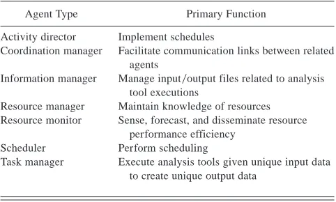
[image:4.612.317.558.582.727.2]The approach to operational design coordination involves tasks and resources being modeled appropriately, as shown in Tables A.1 and A.2 of Appendix A. A detailed description of the use of the knowledge attributes of tasks and resources is given in the industrial case study in Section 4, and a summary of the primary function of each agent type is pre-sented in Table 1.
Table 1. Primary functions of agent types
Agent Type Primary Function
Activity director Implement schedules
Coordination manager Facilitate communication links between related agents
Information manager Manage input0output files related to analysis
tool executions
Resource manager Maintain knowledge of resources Resource monitor Sense, forecast, and disseminate resource
performance efficiency Scheduler Perform scheduling
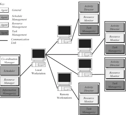
Figure 1 indicates the location of the agent types within a computer network of workstations and the aspects of oper-ational design coordination of each type of agent and com-munication links. In Figure 1, the computer network is shown as consisting of a workstation that is local to the user of the DCS and four remote workstations. The local workstation is that on which the user invokes the DCS. Remote work-stations are used to perform executions of analysis tools.
With regard to Figure 1, and within any application of the DCS, a single coordination manager, scheduler and resource manager operate on the workstation local to the user of the system. Information managers are also situated on the local workstation, and one exists per analysis tool to be used in the computational process. A task manager is present for each analysis tool on every remote workstation being used in the computer network. Each remote workstation is also allo-cated a resource monitor and an activity director.
3.2. DCS architecture
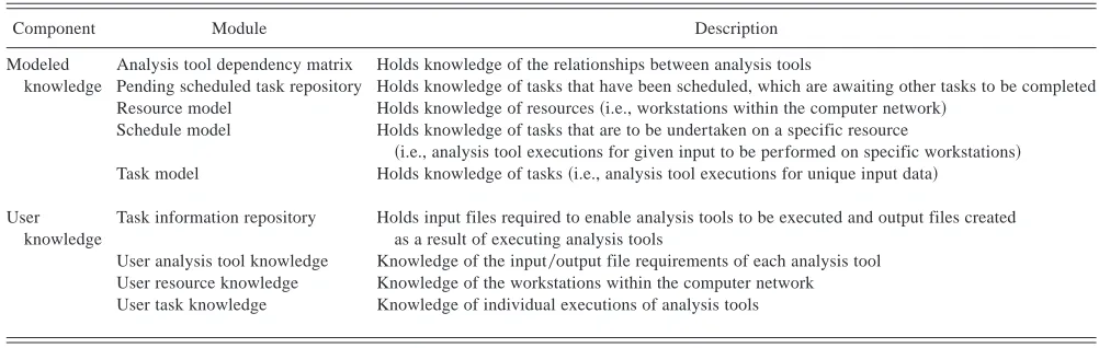
As shown in Figure 2, the DCS comprises an agent frame-work, modeled knowledge, and user knowledge. The agent framework, which was reviewed in Section 3.1, acquires knowledge provided by the user to derive modeled knowl-edge. The agent framework then maintains and uses mod-eled knowledge through the application of real-time operational design coordination.
[image:5.612.83.526.300.704.2]In Figure 2, a distinction is made between the communi-cation between agents and the interactions between agents and knowledge modules, as the nature of these exchanges are different. That is, communication between agents involves asynchronous message passing using transmission control protocol0Internet protocol. Interactions between agents and knowledge modules entail agents extracting or modifying knowledge within the modules to enable them to
Fig. 2. The design coordination system architecture.
G.
Coates
et
perform some action. These interactions are discussed throughout the industrial case study presented in Section 4. With regard to Figure 2, a summary of the various mod-ules associated with the modeled knowledge and user knowl-edge components of the DCS architecture is presented in Table 2.
The DCS is written in the C11programming language and operated on a Unix platform consisting of a network of Sun Microsystems workstations~Ultra 10170 and Ultra 10!. Before using the DCS, its executable and those of all analy-sis tools must be copied into a directory on the local work-station, as illustrated in Figure 1. Once the DCS executable is invoked, knowledge must be provided by the user in accordance with Table 2 ~i.e., knowledge of the analysis tools, tasks and associated information, and resources!. That is, the user defines a profile for each analysis tool, which consists of knowledge of the input–output file require-ments for each tool. On the basis of knowledge of the analy-sis tools, task knowledge is provided by the user in regard to the number of executions of each analysis tool. Any input file or files for the first analysis tool to be executed in the computational process are copied by the user and stored in the task information repository. The user also provides knowledge of the resources~i.e., host names of the remote workstations within the computer network that can be used by the DCS to execute analysis tools!. On the basis of the knowledge provided by the user, the analysis tool depen-dency matrix, task model, and resource model are con-structed and are then used and maintained by DCS agents throughout the computational process. The scheduler is the only agent with direct access to the analysis tool depen-dency matrix and task model. The resource model is only accessible via the resource manager.
4. ENGINEERING INDUSTRIAL CASE STUDY
Siemens Power Generation Limited provided a practical case study to enable the application of the DCS. Within the
company, the Turbine Engineering Department is responsi-ble for the design and development of turbine modules to upgrade0replace existing plants. The computational pro-cess of turbine blade design involves a suite of analysis tools that the designer uses in the selection of blades and blade path and in the calculation of the associated stresses and vibration characteristics of the blades. The determinis-tic analysis tools are related as shown in Figure 3. The naming convention of the analysis tools is company specific. In Figure 3, the computational process is shown to in-volve 8 analysis tools. Further, analysis tool TF23225 is used for three purposes and, as such, is modeled as 3 indi-vidual analysis tools ~i.e. TF23225_1, TF23225_2, and TF23225_3!. Thus, the case study to be used consists of 10 analysis tools. For reasons of confidentiality, descriptions of these analysis tools were not divulged by the company. As a result, throughout this section, the analysis tools are referred to by their associated TF number.
Within Siemens Power Generation Limited, experienced design engineers manually manage the computational pro-cess of turbine blade design. That is, executions of analysis tools are performed sequentially, with the appropriate man-agement of the large quantity of information and data held within files between each run. This means of managing information and data is time consuming and error prone. The manual enactment of a single run of the computational process, shown in Figure 3, takes approximately 8 min using a single workstation comparable to those used within the DCS~Whitfield et al., 2002!. As such, the duration~min!of the complete computational process is approximately a fac-tor of eight applied to the number of process runs. For com-parative purposes of this case study, a single run of the computational process is considered.
4.1. Initialization
On instantiation of the DCS, a single coordination man-ager, resource manman-ager, and scheduler are created. In this
Table 2. Summary of modeled knowledge and user knowledge
Component Module Description
Modeled Analysis tool dependency matrix Holds knowledge of the relationships between analysis tools
knowledge Pending scheduled task repository Holds knowledge of tasks that have been scheduled, which are awaiting other tasks to be completed Resource model Holds knowledge of resources~i.e., workstations within the computer network!
Schedule model Holds knowledge of tasks that are to be undertaken on a specific resource
~i.e., analysis tool executions for given input to be performed on specific workstations! Task model Holds knowledge of tasks~i.e., analysis tool executions for unique input data!
User knowledge
Task information repository Holds input files required to enable analysis tools to be executed and output files created as a result of executing analysis tools
User analysis tool knowledge Knowledge of the input0output file requirements of each analysis tool
case study, 10 analysis tools and four resources are used. Thus, 10 information managers are also created, as well as 40 task managers, four resource monitors, and four activity directors.
Initially, the coordination manager receives messages from all agents. Knowledge contained within each initial com-munication relates to attributes of the agent, which is depen-dent on agent type. After recording these attributes, the manager replies to the agents, acknowledging their regis-tration. Once registered, agents request knowledge of related agents from the coordination manager. This knowledge enables related agents to communicate directly with one another, via message passing, as and when required, such that they can work cooperatively and coordinate their actions.
4.1.1. Designer-defined tasks
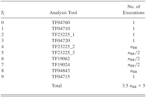
The designer provides knowledge of the tasks to be under-taken~i.e., executions of analysis tools with unique input data!. The computational process involves a number of executions of each of the analysis tools, as shown in Table 3, where TIis a unique identification index for each analysis
tool and nBR is the number of turbine blade rows under consideration.
[image:8.612.83.555.81.436.2]In this case study, the number of turbine blade rows under consideration is 36 ~18 fixed and 18 rotating!. Thus, the total number of tasks to be undertaken is 131.
Fig. 3. The computational process of turbine blade design: analysis tools. *Unique file qualifier.
Table 3. Number of analysis tool executions
TI Analysis Tool
No. of Executions
0 TF04760 1
1 TF04710 1
2 TF23225_1 1
3 TF04720 1
4 TF23225_2 nBR
5 TF23225_3 nBR02
6 TF19062 nBR02
7 TF19024 nBR02
8 TF04843 nBR
9 TF04715 1
[image:8.612.316.558.566.727.2]For each task, the designer allocates TI, TL, TDD, T@TIn#, and
T@TOut#. The variable TLis a task identification index that is
local to its associated analysis tool. As an example, within the computational process, as analysis tool TF23225_2~with TI54!will be executed 36 times, each with a unique input file, then for TI54, TLranges from 0 to 35. The variable TDD is the datum duration of a task used for comparative pur-poses when considering resources of varying performance efficiency to undertake the task, and T@TIn#defines the infor-mation~i.e., input files!needed to be available before a task is undertaken. Similarly, T@TOut#defines the information~i.e.,
output files!produced on the completion of a task. 4.1.2. Resource model
The construction and maintenance of the resource model is the primary responsibility of the resource manager. The upkeep of the knowledge held within the resource model provides the basis for the optimized utilization of the resources throughout the computational process.
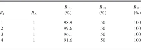
The resource manager acquires user-supplied knowledge at the outset of the operation of the DCS and holds it in the resource model. Specifically, for each of the four resources to be used, the resource model consists of knowledge attributes as shown in Table 4. Here, RIis a unique identi-fication index, and RAis an indication of whether a resource is available to be used, that is, RA5$0, 1%, where 0 indi-cates that a resource is unavailable and 1 signifies that it is available. The variable RFEis the forecasted performance efficiency expressed as a percentage. Within the operating environment of the DCS, RFEis a measure of the potential performance efficiency that can be used and RLTand RUT are lower and upper performance efficiency thresholds, respectively, which if transgressed result in the consider-ation of rescheduling.
The resource manager maintains values of RFEwithin the resource model with the assistance of the resource moni-tors. The initial values assigned to RFEfor each resource are calculated by the respective resource monitor based on val-ues of monitored performance efficiency, RME, observed over a period of time before scheduling. The procedure of obtaining RFEis explained in Sections 4.2.7 and 4.2.8.
4.1.3. Construct an analysis tool dependency matrix An analysis tool dependency matrix is a representation of the relationships between the analyses tools involved in
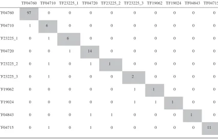
the computational process and is used to assist in the con-struction of a task model. To construct a dependency matrix, the scheduler uses knowledge provided by the user regard-ing each analysis tool to be used in the computational pro-cess. Knowledge of dependencies is established using the input and output requirements ~i.e., the input and output files needed!for each analysis tool. By comparing the input requirements of each analysis tool, T@TIn#, against the output requirements, T@TOut#, of all other analysis tools, the sched-uler is able to determine the dependency relationships between them. Within the matrix, off-diagonal elements marked 0 represent nondependency and elements marked 1 signify dependency. The diagonal elements of the depen-dency matrix show the datum durations of executing each analysis tool, which are obtained from the user by perform-ing arbitrary executions usperform-ing a reference resource in the local area network. The dependency matrix for the compu-tational process, shown in Figure 3, is presented in Table 5. With regard to Table 5, as an example, for an execution of TF23225_2, the corresponding executions of TF04710 and TF04720 must be completed.
4.1.4. Construct a task model
A task model represents knowledge of the tasks to be undertaken in the computational process~i.e., executions of the analysis tools and the unique files required to do so!. The scheduler is responsible for ensuring that the task model is constructed and maintained throughout the computa-tional process. To construct a task model, the scheduler uses knowledge provided by the user and contained within the analysis tool dependency matrix.
Table 6 represents the analysis tool dependency matrix shown in Table 5, with each analysis tool assigned a value for TIin accordance with Table 3. In addition, Table 7 rep-resents some of the knowledge of tasks held within the task model. For the analysis tool with TI 56 ~i.e., TF19062!, two tasks are shown, each with different values assigned to TLbecause they have unique input and output files sig-nified by T@TIn# and T@TOut#. Using the analysis tool
depen-dency matrix, it can be determined that input for each task associated with the analysis tool with TI56 is created as output from the analysis tool with TI55.
As stated in Section 4.1.1, knowledge of tasks defined by the designer comprises TI, TL, TDD, T@TIn#, and T@TOut#. Within
the task model, tasks are assigned additional knowledge
~namely, TG, TC, TN, and T@TG#!. The variable TGis an
identi-fication index for a task within the context of all tasks and is used for scheduling and rescheduling purposes. With regard to the computational process, because there are a total of 131 analysis tool executions, the TGvalue ranges from 0 to 130. The variable TCrepresents whether or not a task has been com-pleted such that TC5$0, 1%, where 0 indicates noncomple-tion and 1 signifies complenoncomple-tion. In addinoncomple-tion, the analysis tool dependency matrix, which was constructed using knowl-edge of T@TIn# and T@TOut# for each analysis tool, is used to
[image:9.612.54.295.640.725.2]determine TNand T@TG#for each task. The variable TNis the Table 4. Resource model
RI RA
RFE ~%!
RLT ~%!
RUT ~%!
1 1 98.9 50 100
2 1 99.6 50 100
3 1 96.1 50 100
number of dependencies of a task, and T@TG#is a matrix
defin-ing TGof each of these dependencies.
4.2. Operation
For the purposes of this case study, the operation of the agents within the DCS has been divided into subsections 4.2.1 to 4.2.16. The order in which these subsections are presented corresponds to the occurrence of agent actions during the computational process.
4.2.1. Derive an original schedule
The primary role of the scheduler is to satisfy the objec-tives of scheduling a number of tasks on the least number of
available resources while consuming the least amount of those resources, such that dependencies are preserved and the overall time to complete the tasks is minimized. At the outset of the computational process, the scheduler derives an original schedule using a multiobjective genetic algo-rithm ~MOGA; Todd, 1997; Todd & Sen, 1997a, 1997b! allied with knowledge of outstanding tasks and available resources from their respective models. Initially, all tasks are outstanding ~i.e., for each task TC50!and, thus, all need to be scheduled. Task knowledge required for use with the MOGA comprises TG, TDD, TN, and T@TG#for each task.
[image:10.612.96.522.82.354.2]Furthermore, the scheduler notes the number of tasks to be scheduled~nTS!and the cumulative number of dependen-cies for those tasks~nTD!. As indicated in the resource model Table 5. Analysis tool dependency matrix
TF04760 TF04710 TF23225_1 TF04720 TF23225_2 TF23225_3 TF19062 TF19024 TF04843 TF04715
TF04760 97 0 0 0 0 0 0 0 0 0
TF04710 1 6 0 0 0 0 0 0 0 0
TF23225_1 0 1 6 0 0 0 0 0 0 0
TF04720 0 0 1 14 0 0 0 0 0 0
TF23225_2 0 1 0 1 1 0 0 0 0 0
TF23225_3 0 1 0 0 0 2 0 0 0 0
TF19062 0 0 0 0 0 1 1 0 0 0
TF19024 0 0 0 0 0 1 1 1 0 0
TF04843 0 0 0 1 1 0 0 0 1 0
TF04715 0 1 0 1 0 0 0 0 0 11
Table 6. Analysis tool dependency matrix
TI 0 1 2 3 4 5 6 7 8 9
0 97 0 0 0 0 0 0 0 0 0
1 1 6 0 0 0 0 0 0 0 0
2 0 1 6 0 0 0 0 0 0 0
3 0 0 1 14 0 0 0 0 0 0
4 0 1 0 1 1 0 0 0 0 0
5 0 1 0 0 0 2 0 0 0 0
6 0 0 0 0 0 1 1 0 0 0
7 0 0 0 0 0 1 1 1 0 0
8 0 0 0 1 1 0 0 0 1 0
[image:10.612.59.299.589.726.2]9 0 1 0 1 0 0 0 0 0 11
Table 7. Analysis tool task model
TI TL . . . T@TIn# T@TOut#
0 0 . . . hp1.760.inp hp1.720.inp 1 0 . . . hp1.b1d hp1.b1d 2 0 . . . hp1.b2d hp1.b2d
3 0 . . . hp1.720.inp hp1.720.sls, hp1.720.ben
. . . .
6 12 . . . hp1.026.062.inp hp1.026.062.out, hp1.026.024.mat 6 13 . . . hp1.028.062.inp hp1.028.062.out, hp1.028.024.mat
. . . .
. . . .
[image:10.612.218.542.590.726.2]shown in Table 4, each of the four resources are available for utilization because RA51 for all of them. With regard to each of the available resources, the scheduler requests that the resource manager provide RIand RFE. The sched-uler also notes the number of resources to be considered for scheduling, nRS.
Executing the MOGA results in a set of solutions~i.e., schedules! being created that satisfy the three objectives defined above. Figure 4 illustrates a set of solutions created by using the MOGA with respect to minimizing the con-flicting objectives.
Within the set of solutions created, a subset exists known as the Pareto ~1896! optimal set of solutions~i.e., sched-ules!. A Pareto optimal set comprises solutions in which no increase can be achieved in any of the criteria without result-ing in a simultaneous decrease in at least one of the remain-ing criteria.
The scheduler identifies the Pareto optimal set of solu-tions and then uses multicriteria decision making to select the most appropriate, or best, schedule from this set. The criteria used coincide with the objectives of completing the computational process in the least time using the least num-ber of resources while consuming the least amount of those resources. That is, they strive to minimize time, number of resources, and resource use. The first criterion applied to the Pareto optimal set is that of minimizing the time
esti-mate to complete all scheduled tasks. Thus, the schedule with the least time estimate to complete the tasks scheduled is selected. In the event that more than one schedule within the Pareto optimal set satisfies this first criterion, a second criterion is applied such that the schedule with the least number of resources used to achieve the completion of the tasks scheduled is chosen. Again, in the event that more than one schedule satisfies the first and second criterion, a third, and final, criterion is used. That is, the schedule exhib-iting the least cumulative percentage utilization of the resources employed is selected. If there are a number of schedules within the Pareto optimal set that satisfy all cri-teria, then a schedule is arbitrarily chosen because all of these schedules are equally as good.
An example original schedule selected from the Pareto optimal set of solutions is shown in Figure 5.
4.2.2. Construct original schedule models
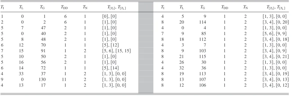
[image:11.612.144.451.407.713.2]The scheduler uses the best optimized schedule to con-struct an original schedule model for each resource to be used. The responsibility of administering the enactment of each original schedule model lies with the activity director of the corresponding resource. Thus, the scheduler notifies and provides each activity director with the respective orig-inal schedule model. In Table 8, the best schedule is pre-sented in the form of an original schedule model for resource
RI51. Furthermore, tasks are listed in the order that they should be undertaken.
In Table 8 T@TI#and T@TL#are matrices defining TIand TLof
each dependency of a task.
4.2.3. Check dependencies and direct tasks
On being provided their original schedule models, each activity director begins administering the designated tasks to be undertaken. As indicated in Table 8, the task with TI5 1 and TL50 is the first task to be undertaken using resource RI51 ~i.e., the only execution of analysis tool TF04710 using input file hp1.b1d and creating output file hp1.b2d!. For brevity, in the remainder of this article, a task’s TIand TLwill be abbreviated to T~TI, TL!; that is, the task previ-ously stated is denoted as T~1, 0!.
On inspecting its associated original schedule model, the activity director recognizes that this task is dependent on the completion of T~0, 0!; that is, the single execution of analysis tool TF04760 as shown in Figure 6. This
depen-dency exists because TF04710 requires the output file pro-duced on executing TF04760~i.e., hp1.b1d!as input. Thus, the activity director confers with the scheduler to establish whether the dependency has been completed. The sched-uler checks the task model to determine TCof the depen-dency T~0, 0!.
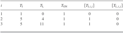
Because the execution of TF04760 has not been com-pleted~i.e., TC50!, the execution of TF04710 cannot com-mence. As such, the scheduler records within the pending scheduled task repository that T~1, 0!is awaiting the com-pletion of T~0, 0!. Similarly, as shown in Figure 6, the first task to be undertaken using resource RI53@i.e., T~5, 4!# and RI54 @i.e., T~5, 11!#cannot start because it requires information that will only become available on the comple-tion of T~1, 0!. At the outset of the computational process, only T~0, 0!on resource RI52 is able to commence, because it has no dependencies. The pending scheduled task repos-itory at the point described is shown in Table 9, where i5
[image:12.612.72.545.64.253.2]$1, 2, . . . , nPST%, j5$1, 2, . . . , TON,i%, nPSTis the number of Fig. 5. An optimized schedule.
Table 8. Original schedule model for resource RI51
TI TL TG TDD TN T@TI#, T@TL# TI TL TG TDD TN T@TI#, T@TL#
1 0 1 6 1 @0#,@0# 4 5 9 1 2 @1, 3#,@0, 0#
2 0 2 6 1 @1#,@0# 8 20 114 1 2 @3, 4#,@0, 20#
5 7 47 2 1 @1#,@0# 4 0 4 1 2 @1, 3#,@0, 0#
5 0 40 2 1 @1#,@0# 7 9 85 1 2 @5, 6#,@9, 9#
5 8 48 2 1 @1#,@0# 8 18 112 1 2 @3, 4#,@0, 18#
6 12 70 1 1 @5#,@12# 4 3 7 1 2 @1, 3#,@0, 0#
7 15 91 1 2 @5, 6#,@15, 15# 8 9 103 1 2 @3, 4#,@0, 9#
5 10 50 2 1 @1#,@0# 8 21 115 1 2 @3, 4#,@0, 21#
5 16 56 2 1 @1#,@0# 4 26 30 1 2 @1, 3#,@0, 0#
6 14 72 1 1 @5#,@14# 4 32 36 1 2 @1, 3#,@0, 0#
4 33 37 1 2 @1, 3#,@0, 0# 8 19 113 1 2 @3, 4#,@0, 19#
9 0 130 11 2 @1, 3#,@0, 0# 8 13 107 1 2 @3, 4#,@0, 13#
[image:12.612.59.564.561.728.2]pending scheduled tasks, and TONis the number of outstand-ing dependencies of a pendoutstand-ing scheduled task.
In the event of a task being ready to be undertaken that has no dependencies, the activity director omits this con-sultation with the scheduler and directly contacts the rele-vant task manager, instructing it to commence undertaking the specified task.
4.2.4. Request, provide, and supply task information0undertake tasks
The principal duty of a task manager is the execution of its associated analysis tool for a unique input file or files. An instruction to a task manager indicating that a specific task should commence is provided by its related activity director. As such, before undertaking the task T~0, 0!, that is, executing analysis tool TF04760, the relevant task man-ager requests that its related information manman-ager provide the necessary input file according to T@TIn# ~i.e., hp1.760.
inp!. In response, the information manager locates and retrieves this input file from the task information reposi-tory. On notification that the requested information has been provided, the task manager commences with the execution
of its associated analysis tool. Once TF04760 has been executed, the task manager informs its related information manager such that the output file created~i.e., hp1.b1d, in accordance with T@TOut#!, can be stored in the task
informa-tion repository, which is accessible by all informainforma-tion man-agers. Thus, these files are available in the event of them being required as input for the execution of other analysis tools, specifically, at this time in the process, the pending scheduled task T~1, 0!.
4.2.5. Update task model
On completion of T~0, 0!, the task manager informs its related activity director, which then informs the scheduler of this fact. The scheduler updates the task model to reflect the completion of the task by setting TC51. Updating the task model ensures that in the event of rescheduling, only outstanding tasks will be considered~i.e., tasks with TC50!.
4.2.6. Remove dependencies and commence direction of pending scheduled tasks
[image:13.612.120.489.64.300.2]In addition to updating the task model, the scheduler updates the pending scheduled task repository. As such, any tasks solely awaiting the completion of the recently com-pleted dependency may be undertaken. Specifically, as T~0, 0! has been completed, the scheduler removes this dependency from the pending scheduled task repository and decrements TON where appropriate. As a consequence, as TON becomes nil for T~1, 0!, that is, this task has no out-standing dependencies, it can be undertaken. The commence-ment of this task is instigated by the scheduler, who informs the appropriate activity director.
Fig. 6. The initial tasks to be undertaken.
Table 9. Pending scheduled task repository
i TI TL TON @TI, i, j# @TL, i, j#
1 1 0 1 0 0
2 5 4 1 1 0
[image:13.612.53.293.661.726.2]4.2.7. Monitor resources
Each resource monitor is responsible for sensing, fore-casting, and reporting performance efficiency of its associ-ated resource. Throughout the computational process, each resource monitor observes the various constituents of cen-tral processing unit ~CPU! utilization of its associated resource such that any violations of the upper or lower per-formance efficiency thresholds can be identified. In partic-ular, a resource monitor establishes what percentage of the current CPU utilization of its associated resource is attrib-uted to
•
user processes, Ruser, which are the computer pro-grams being run by users;•
system processes, Rsystem, which is UNIX kernel code; and•
idle, Ridle, which is not being utilized.Furthermore, Ruseris divided into the proportion of CPU utilization attributed to computer programs that are being executed within the DCS ~i.e., analysis tools, RDCS! and that are unrelated to the DCS~Rother!. On the basis of obser-vations of CPU utilization over a period of time, each resource monitor calculates the monitored performance effi-ciency of its associated resource at time t, RMEt, using the equation
RMEt5RCF3
F
Ridlet1RDCSt1Rothert
nps
~11Rsystemt!
G
.The resource coefficient~RCF!is a relative measure of the processor speed of a resource such that the forecasted per-formance efficiencies determined for all resources are directly comparable. This is required for purposes of sched-uling and reschedsched-uling. In addition, nps is the number of processes being executed on the resource.
The CPU utilization and monitored performance effi-ciency of resource RI54 over a period of the computa-tional process are shown in Figure 7 as observed by the associated resource monitor.
In Figure 7, it can be seen that at approximately t560 s there is a deviation in monitored performance efficiency that transgresses its lower threshold of RLT550%, which instigates the consideration of rescheduling. Further, for this resource, RMEfluctuates between 38 and 48% during the remainder of the computational process. Although not shown in Figure 7, for resources RI51, 2, and 3, monitored performance efficiency is approximately 99% for the remain-der of the computational process.
4.2.8. Forecast and revise resource model
Because of the monitored performance efficiency of resource RI54 falling below the lower threshold of 50%,
the associated resource monitor forecasts future perfor-mance efficiency. This is achieved by performing a regres-sion analysis using orthogonal polynomials with recent values of monitored performance efficiency. The regres-sion equation derived for resource RI54 is
RFE, t5 20.1979t417.7977t32111.97t21683.18t21395.9.
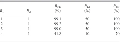
The resource monitor supplies the forecasted performance efficiency to the resource manager, which updates the resource model accordingly. The resource manager also resets the values of RLTor RUTto 10 and 70%, respectively. The reason for resetting these values is to avoid resched-uling being considered again as a result of insignificant deviations in monitored performance efficiency about the previous lower threshold. The resource manager also requests that all other resource monitors determine and report fore-casts of performance efficiency for their associated resource. The resource manager then updates the resource model, as shown in Table 10.
Subsequently, based on the up to date knowledge of resource forecasted performance efficiencies, the resource manager instructs the scheduler to consider rescheduling.
4.2.9. Decision making for rescheduling0deriving interim schedule models
The decision-making process for rescheduling involves the scheduler assessing whether it would be more econom-ical timewise to continue adhering to the current schedule or to derive and enact a revised schedule. If the time taken to complete the current schedule is greater than the time taken to derive and complete a revised schedule, then the decision is made to reschedule. Otherwise, the current sched-ule is continued.
If rescheduling a proportion of the outstanding tasks is performed, during this period the remaining outstanding tasks can be completed in accordance with interim schedule models. These models are derived as a by-product of esti-mating the time to derive a revised schedule. The concept of interim schedule models ensures that if rescheduling does occur, then the resources remain utilized appropriately dur-ing this period.
Before calculating the time estimates mentioned above, the scheduler requests that all activity directors suspend
their original0revised schedule models. This ensures that knowledge of tasks considered by the scheduler is not sub-ject to change during the decision-making process. Deter-mining the time needed to complete the current schedule, derive a revised schedule, and enact a revised schedule involves the consideration of the 104 outstanding tasks within the original schedule models of each activity director, as presented in Table 11. Shaded cells in Table 11 signify those outstanding tasks that could potentially be included within an interim schedule model because they are independent
~i.e., TN50!at the point at which the scheduler considers rescheduling. Further, the estimated durations of tasks~TED! are summed to determine the cumulative time required to complete the tasks that could potentially be included in the interim schedule models.
4.2.10. Estimated time to complete the current schedule
Estimating the time to complete the current~i.e., origi-nal!schedule~TCCS!initially involves the scheduler supply-ing up to date resource forecasted performance efficiency to each activity director. The activity directors then apply the forecasted performance efficiency of their associated resource to the cumulative datum duration of the outstand-ing tasks within their original schedule models, as shown in Table 12.
Each activity director provides the scheduler with this estimation of the time to complete the associated original schedule model. The scheduler then determines that the orig-inal schedule model with the greatest estimated completion time, indicated by the shaded cells, corresponds with resource RI54. That is, the resource that experienced the significant reduction in forecasted performance efficiency from 91.6 to 41.8%. Thus, if the original schedule models continue to be adhered to under the prevailing forecasted performance efficiency, it is estimated that they would be completed in approximately 79 s~i.e., TCCS579 s!.
4.2.11. Estimated time to derive a revised schedule To estimate the time to derive a revised schedule~TDR!, the scheduler uses empirically derived knowledge of the execution time of the MOGA and knowledge of the out-standing tasks within the original schedule models. Fig-ure 8 presents the empirical relationship between the number of tasks to be scheduled~nTS!for a number of resources to be utilized ~nR! and the estimated execution time of the MOGA~TMOGA!. The number of tasks to be scheduled ranges from 20 to 127 because using the MOGA to reschedule beyond these limits would be uneconomical in terms of time.
[image:15.612.54.294.640.725.2]Estimating the time to derive a revised schedule involves establishing the most appropriate combination of outstand-ing tasks to reschedule, whereas the remainder can be com-pleted during this period such that the most appropriate utilization of resources is maintained. Determining the appro-priate combination of tasks involves the application of an Table 10. Revised resource model
RI RA
RFE ~%!
RLT ~%!
RUT ~%!
1 1 99.1 50 100
2 1 99.2 50 100
3 1 99.0 50 100
iterative procedure. Step 1 involves estimating the execu-tion time of the MOGA given the number of tasks to be rescheduled and the number of resources to be utilized. On the basis of the time estimate from step 1, step 2 entails using the original schedule model for each resource to ascer-tain the number of outstanding tasks that could be com-pleted during rescheduling. Step 3 involves deducting the cumulative number of outstanding tasks able to be
com-pleted utilizing all resources determined in step 2 from the number of tasks considered for rescheduling in step 1. The results from applying the procedure are shown in Table 13, where nTRSis the number of outstanding tasks to resched-ule, nTCRS is the number of tasks that could be completed using a particular resource during rescheduling given the estimated time to derive a revised schedule using the MOGA, and TTCRSis the time taken to complete a number of tasks using a particular resource during rescheduling.
[image:16.612.63.561.76.450.2]The procedure converges when the time taken to resched-ule a number of outstanding tasks is as nearly coincident as possible with the completion of those remaining. Thus, the idle time of each resource is minimized. Table 13 shows that convergence to the optimum solution with respect to concurrent rescheduling0task completion is reached after four iterations. That is, the scheduler should reschedule 60 tasks, estimated to take approximately 20 s ~i.e., TDRS5 20.3 s!, according to the regression equation associated with four resources shown in Figure 8. During the period of rescheduling, 44 tasks are estimated as being able to be Table 11. Outstanding tasks within original schedule models
RI51, RFE599.1% RI52, RFE599.2% RI53, RFE599.0% RI54, RFE541.8%
TG TN TDD STED TG TN TDD STED TG TN TDD STED TG TN TDD STED
72 1 1 — 76 1 1 — 28 0 1 1.01 65 0 1 2.39
37 0 1 1.01 43 0 2 2.02 86 1 1 — 83 1 1 —
130 0 11 12.11 88 0 1 3.02 74 0 1 2.02 58 0 1 4.78
17 0 1 13.12 60 0 1 4.03 34 0 1 3.03 49 0 2 9.57
9 0 1 14.13 54 0 2 6.05 64 0 1 4.04 81 0 1 11.96
114 1 1 — 53 0 2 8.07 12 0 1 5.05 68 0 1 14.35
4 0 1 15.14 24 0 1 9.07 102 1 1 — 78 1 1 —
85 2 1 — 35 0 1 10.08 39 0 1 6.06 16 0 1 16.75
112 1 1 — 33 0 1 11.09 87 0 1 7.07 118 1 1 —
7 0 1 16.15 18 0 1 12.10 21 0 1 8.08 25 0 1 19.14
103 1 1 — 19 0 1 13.11 66 0 1 9.09 92 1 1 —
115 1 1 — 109 1 1 — 31 0 1 10.10 123 1 1 —
30 0 1 17.15 22 0 1 14.11 117 1 1 — 8 0 1 21.53
36 0 1 18.16 90 2 1 — 67 1 1 — 26 0 1 23.92
113 1 1 — 108 1 1 — 15 0 1 11.11 116 1 1 —
107 1 1 — 38 0 1 15.12 105 1 1 — 129 1 1 —
106 1 1 — 128 1 1 — 94 1 1 — 14 0 1 26.32
111 1 1 — 96 1 1 — 104 1 1 —
121 1 1 — 59 0 1 12.12 27 0 1 28.71
100 1 1 — 97 1 1 — 10 0 1 31.10
99 1 1 — 61 1 1 — 32 0 1 33.49
6 0 1 16.13 79 1 1 — 71 1 1 —
5 0 1 17.14 23 0 1 13.13 98 1 1 —
122 1 1 — 11 0 1 35.89
13 0 1 18.15 101 1 1 —
89 2 1 — 95 1 1 —
82 1 1 — 84 1 1 —
20 0 1 19.15 29 0 1 38.28
120 1 1 — 127 1 1 —
77 1 1 — 110 1 1 —
124 1 1 — 126 1 1 —
119 1 1 — 125 1 1 —
Table 12. Estimated times to complete current schedule models
RI
STDD ~s!
RFE ~%!
STED5STDD0RFE ~s!
1 27 99.1 27.2
2 35 99.2 35.3
3 23 99.0 23.2
[image:16.612.60.299.641.725.2]completed using the four resources. On the basis of their most recent forecasted performance efficiency, resources RI51, 2, and 4 would be utilized for approximately 19 s, whereas resource RI53 for approximately 13 s. As a con-sequence, not only has the optimized time to reschedule an appropriate number of outstanding tasks been determined but also the tasks to be completed during this period have been identified~i.e., those for inclusion within the interim schedule models!. Values of TGwithin the interim schedule models are shown in Table 14.
Concurrent rescheduling0task completion results in a mean resource idle time of approximately 3 s. Because resources idle time is minimized, the arrival of the revised
schedule is expected to be as close as possible to the com-pletion of the interim schedule models.
4.2.12. Estimated time to complete a revised schedule
[image:17.612.89.516.61.325.2]Estimating the time to complete a revised schedule~TCRS! involves simulating the grouping and assignment of tasks to be rescheduled to the allocated resources. Grouping tasks enables the identification of groups that must be under-taken sequentially, which consist of tasks that may be com-pleted concurrently. Assigning tasks to resources is done in accordance with these groups such that the greatest cumu-lative time to complete the tasks can be obtained.
Fig. 8. The estimated execution time of MOGA.
Table 13. Determination of time to reschedule and concurrently complete tasks
Resources
RI51 RI52 RI53 RI54
Iteration nTRS
TMOGA
~s! nTCRS
TTCRS
~s! nTCRS
TTCRS
~s! nTCRS
TTCRS
~s! nTCRS
TTCRS
~s! SnTCRS
1 104 37.6 8 18.16 16 19.15 13 13.13 14 35.89 51
2 53 18.6 8 18.16 15 18.15 13 13.13 6 16.75 42
3 62 20.8 8 18.16 16 19.15 13 13.13 7 19.14 44
[image:17.612.88.525.603.728.2]Step1. Determine task groups: To determine the groups into which the 60 tasks to be rescheduled could be divided, an assessment of the tasks dependencies is made ~i.e., whether it0they was0were completed in accordance with an original schedule model, will be completed in accor-dance with an interim schedule model, or will be resched-uled for inclusion with a revised schedule model!.
Forty-eight tasks would not have any outstanding depen-dencies once rescheduled because
•
they never had any dependencies,•
their dependencies were completed in accordance with the original schedule models before the consideration of rescheduling, or•
their dependencies will be completed in accordance with the interim schedule models during the period of rescheduling.Similarly, as a result of rescheduling, only 12 tasks will have outstanding dependencies within the revised schedule models. As a consequence, the 60 tasks to be considered for rescheduling can be divided into two groups, the first group comprising 48 tasks and the second group consisting of 12 tasks. Further, these groups must be completed sequen-tially. However, tasks within each group may be completed in parallel because they are independent of other tasks in the same group.
Step2. Distribute group tasks among resources: Given that the datum duration of each outstanding task to be rescheduled is 1 s, Table 15 presents information regarding
how the groups of tasks identified in Step 1 could be dis-tributed among the four resources such that their collective time to completion is minimized.
Based on Table 15, the TCRSis approximately 18 s. This corresponds to the greatest cumulative time to complete the groups of tasks, as indicated by the shaded row of Table 15.
4.2.13. Decision to reschedule
The scheduler makes the decision to reschedule because the estimated time to complete the original schedule is greater than the time it is estimated to derive and complete a revised schedule, which is
TCCS~79 s! .TDRS~20 s!1TCRS~18 s!.
Furthermore, the scheduler instructs each activity director to administer the interim schedule model during the period of rescheduling. These models~Table 14!were constructed as a by-product of determining the estimated time to derive a revised schedule. In addition, the completion of the interim schedule models is intended to be near coincident with the completion of rescheduling. Thus, the transition delay between the current and revised schedules is minimized.
4.2.14. Modify task model
[image:18.612.94.526.78.152.2]Before rescheduling, the scheduler modifies the task model. This is required because knowledge held in the task model is used in the derivation of the revised schedule mod-els. Knowledge in the task model modified by the scheduler consists of the TCof those tasks to be completed in accor-dance with the interim schedule models, the TG, T@TG#, and
Table 14. Interim schedule models
RI TG
1 37 130 17 9 4 7 30 36
2 43 88 60 54 53 24 35 33 18 19 22 38 6 5 13 20
3 28 74 34 64 12 39 87 21 66 31 15 59 23
4 65 58 49 81 68 16 25
Table 15. Assignment of rescheduled tasks
Group 1: 48 Tasks Group 2: 12 Tasks
RI
RFE ~%!
No. of Tasks Assigned
STED5STDD0RFE ~s!
No. of Tasks Assigned
STED5STDD0RFE ~s!
Total Time ~s!
1 99.1 14 14.13 4 4.04 18.17
2 99.2 14 14.11 4 4.03 18.14
3 99.0 14 14.14 3 3.03 17.17
[image:18.612.93.524.622.727.2]TNof the 60 outstanding tasks to be rescheduled and con-sidered in Table 15.
4.2.15. Derive revised schedule models0complete interim schedule models
To derive the revised schedule models, the scheduler uses the MOGA with knowledge held within the modified task model and revised resource model. The actual duration of rescheduling the 60 tasks was approximately 23 s, which is 3 s greater than estimated. As such, the decision to resched-ule was not affected.
During rescheduling, the activity directors administer the enactment of their respective interim schedule models. Because the tasks included within the interim schedule mod-els have no outstanding dependencies, the need for depen-dency checking is not required. The omission of dependepen-dency checking is essential because it requires scheduler involve-ment, which is not possible because this agent is occupied performing rescheduling during the enactment of the interim schedule models.
4.2.16. Complete revised schedule models
Once rescheduling has been performed and the interim schedule models are completed simultaneously, then the revised schedule models are enacted. The computational process then progresses until all tasks have been completed in accordance with the revised schedule models.
In the application of the DCS presented in this article, the time taken to complete one run of the computational process is approximately 3 min, while utilizing four work-stations of variable performance efficiency. As stated at the outset of Section 4, an experienced engineer can complete one run of the process in approximately 8 min using a sin-gle workstation. However, it is not only the additional work-stations employed by the DCS that contributes to the reduction in the duration of the computational process but also the approach to real-time operational design coordina-tion. That is, the techniques and their links and interrela-tionships within the approach demonstrate the coherent management of tasks, resources, and schedules can result in the computational process being performed in a timely and appropriate manner. More specifically, the integrated approach provides a means of undertaking tasks in a struc-tured fashion, and resource utilization is continuously opti-mized throughout the computational process, in accordance with appropriately and dynamically generated schedules, within a computer environment that is susceptible to fluc-tuations in performance at any time. Indeed, Siemens Power Generation Limited indicated in correspondence that, “while there are obvious benefits of automating the process involv-ing the use of the analysis tools on a network of machines, I appreciate that it is the underlying real-time operational design coordination approach and the work in setting up the architecture for this that is of key importance” ~Coates, 2001!.
5. DISCUSSION
This section presents a discussion of the approach based on the application of the DCS to the industrial case study. As a result of the discussion, strengths and weaknesses of the approach are identified. With regard to the DCS, in Sec-tion 3.1, it was stated that “the composiSec-tion of agents, along with the role each fulfills, enables them to communicate with each other in real time such that they can perform activities involving task management, resource manage-ment and schedule managemanage-ment simultaneously in a coher-ent manner.” As such, in this section, the key elemcoher-ents of coherence, communication, and real-time support are not covered explicitly but, rather, are discussed in the context of managing tasks, resources, and schedules.
5.1. Task Management
In terms of task management, the approach aims to orga-nize and control tasks and their dependencies such that they can be undertaken in a structured manner.
5.1.1. Construction and management of the task model
The construction of the task model, and the subsequent management of the knowledge held within it, provided the basis for the structured undertaking of tasks. Initially, tasks were established based on knowledge provided by the designer regarding the analysis tools within the computa-tional process. Tasks and their associated analysis tools were assigned unique indices~i.e., TI, TL, and TG!, such that they could be identified within the application of the DCS. Knowl-edge of each task’s datum duration ~TDD! was used such that, once scheduled, the estimated duration ~TED! of the task could be determined on the basis of the forecasted performance efficiency of the assigned resource. Knowl-edge of the completion of a task~i.e., TC!was required for purposes of rescheduling such that once a task was com-pleted it could not be considered again. Establishing knowl-edge of dependencies involved the construction and use of an analysis tool dependency matrix. Using the matrix, depen-dency knowledge was established by comparing the input requirements of each task’s associated analysis tool~T@TIn#!
with the output requirements of all other task’s associated analysis tool ~T@TOut#!. During the computational process,
knowledge of dependencies was checked when and where appropriate such that tasks could only be undertaken if their dependencies had been completed.