Active control of a balanced two-stage
pendulum vibration
isolation
system and its application
to laser interferometric
gravity wave detectors
P. J. Veitch,a) N. A. Robertson, C. A. Cantley, and J. Hough
Department of Physics and Astronomy, University of Glasgow, Glasgow GI.2 8QQ Scotland (Received 28 September 1992; accepted for publication 7 January 1993)
The investigation of the servo control of the position of the bottom mass in a balanced two-stage pendulum vibration isolation system is reported. Experimental results for a simple prototype system and predictions based on a model presented in this paper are in good agreement. The application of such a system to a high-sensitivity laser interferometric gravity wave detector is discussed.
1. INTRODUCTION
The isolation of test masses from spurious mechanical vibrations is of growing importance in high-precision ex- periments, particularly in laser interferometric gravita- tional wave detectors. Such detectors rely in principle on sensing the change, induced by a gravitational wave, in the relative separation of a number of almost freely suspended test masses. In its simplest form a laser interferometric detector consists of three test masses suspended at three corners of a square to form two perpendicular arms or baselines; and the relative length of the two arms is mon- itored using laser interferometry between very-high- reflectance mirrors attached to these masses.’
laser shot noise, frequency and intensity noise, and servo electronic noise will also be contained in the signals being examined for gravity waves, and will limit the detector sensitivity.
To maximize the sensitivity of the interferometer the test masses must be isolated from external influences. Thus, the interferometer is housed in a vacuum enclosure to minimize test mass motion produced by acoustic noise, and optical path-length changes due to refractive index fluctuations. The test masses are also isolated from high- frequency ( > few Hz) seismic and environmental vibra- tions using vibration isolation systems which typically in- corporate lead/rubber vibration isolation stacks and pendulums.’ To ensure that Nyquist noise in these systems does not limit the detector sensitivity, the parts of the sus- pension which directly support each of the test masses must have low mechanical losses. However, the seismic excitation of the concomitant high-Q mechanical reso- nances may result in large low-frequency motion of the test masses. To allow the interferometer to operate with max- imum sensitivity the low-frequency motion must be re- duced to < lo-l2 m .I This can be achieved by actively damping the resonazs using auxiliary feedback systems, and using the output from the interferometer to servo con- trol the relative axial positions of the test ‘masses.
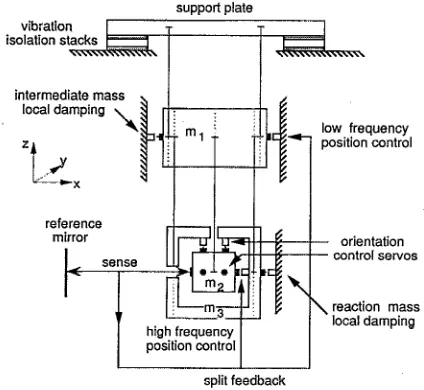
There are several proposed methods for suspending the test masses in high-sensitivity, long baseline laser interfer- ometric detectors.3-5 In this article we briefly describe one possible design,3 shown schematically in Fig. 1, and report results of experimental testing and modeling of a simplified prototype version shown in Fig. 2. The prototype suspen- sion was designed to facilitate the investigation of the servo control of the two-stage balanced pendulum. As will be discussed in Sec. II, it has several features that could not be used in a high-sensitivity interferometer but which do not affect the testing of the servo control.
In the design shown in Fig. 1, care is taken to minimize the number of electromechanical systems acting directly on the test mass as these are potential sources of additional noise. This is accomplished by suspending each test mass using a balanced two-stage pendulum in which the test mass and a reaction mass are suspended from the same intermediate mass, and applying most of the feedback sig- nals to the intermediate and reaction pendulum masses. In particular, the orientation of the test mass and the damping of its pendulum motion are achieved by applying correc- tion forces to the intermediate and reaction masses. In the prototype suspension, however, it was decided for reasons of experimental simplicity to apply the orientation control forces directly to the test mass.
There are several other reasons for choosing a balanced
The interferometer output will also contain’any signals produced by a passing gravity wave. Signals at frequencies above the unity gain frequency of the servo will be directly observable at the interferometer output while signals at frequencies below the unity gain frequency will be best monitored in the feedback signal used to control the rela- tive axial positions of the test masses. Contributions due to
two-stage configuration. First, the vertical isolation pro- vided by the two stages, together with that provided by the multistage vibration isolation stack6 which supports the pendulum (see Fig. 1 ), ensures that axial motion produced by vertical-to-axial cross coupling should be sufficiently small. The balanced final stage provides a well-isolated platform (the reaction mass) from which to apply feed- back forces to the test mass (see below), thereby prevent- ing the coupling of spurious mechanical vibrations to the test mass via the actuator. It also limits the excitation of internal resonances in the stack top-plate by the feedback and helps to maintain the alignment of the test-mass actu- ator as the orientation of the test mass is adjusted.
“Now at Department of Physics and Mathematical Physics, University of The axial position of the test mass is controlled using
Adelaide, Australia. split feedback’?’ in which the large-amplitude, low-
support plate
vibration isolation stack
intermediate mass
test mass
reaction mass
FIG. 1. Schematic diagram of the test mass suspension for a high- sensitivity interferometer. Both the test mass and reaction mass are sus- pended from the intermediate mass using a two-loop (four-wire) pendu- lum suspension. The intermediate mass is suspended using a single loop. Test mass orientation is controlled by acting on the intermediate mass, and its axial position is controlled using split feedback as discussed in the text.
frequency signals are fed back to the intermediate mass and only the smaller-amplitude, higher-frequency signals are fed back to the test mass, as shown in Fig. 2. This may reduce the effects of frequency up-conversion of large low- frequency fluctuations by nonlinearities in the electrome- chanical drive systems. Split feedback systems may be characterized according to the relative values of the “cross- over” frequency and the frequencies of the pendulum nor- mal modes, where the cross-over frequency is the fre- quency which separates the region in which servo control is dominated by the feedback to the intermediate mass
(below the cross-over) from that in which it is dominated by the feedback to the test mass (above the cross-over).
support plate
intermediate mass
reference
control servos
reaction mass
split feedback
RG. 2. Schematic diagram of the prototype balanced two-stage pendu- lum. The masses and uncoupled resonant frequencies of the pendulums are intermediate mass, 11.0 kg and 5.9 s-l; test mass, 3.3 kg and 4.7 s-l; reaction mass, 2.3 kg and 4.7 s-‘.
The system discussed here has a cross-over frequency just below the pendulum normal mode frequencies.
The investigation of an alternative suspension system has recently been reported by Stephens et ~1.~ That design used a nested two-stage pendulum, in which the test mass was enclosed by a concentric cylindrical intermediate mass. The damping of the pendulum modes was achieved by sensing the motion of, and feeding back to, the inter- mediate mass, and the position of the test mass was con- trolled by using the intermediate mass as a reaction mass from which to apply (all of the) correction forces to the test mass.
II. DESCRlPTlbN OF EXPERIMENTAL PENDULUM SUSPENSION
A schematic diagram of the system used to investigate the split feedback servo control of the balanced two-stage pendulum7’8 is shown in Fig. 2. The intermediate mass is suspended by two wire loops from a support plate that is isolated from the ground by a two-stage metal and rubber vibration isolation stack. The test mass is suspended from the intermediate mass by a single loop of wire and enclosed by a box-shaped reaction mass that is suspended from the intermediate mass using two wire loops. This arrangement enabled the test mass’s orientation in tilt (about they axis) and rotation (about the z axis) to be conveniently con- trolled using shadow-position-sensor/magnetic-actuator assemblies” mounted on the reaction mass. As indicated in Sec. I this arrangement may not be suitable for use in a high-sensitivity interferometer, because it could require the application of large forces by the test/reaction mass actu- ators which might result in significant nonlinear produc- tion of noise.
The shadow-position-sensor assemblies consist of a flag which is mounted on the sensed surface, the test mass in this case, and is free to move between a light-emitting di- ode (LED) and photodiode which are mounted on the reference surface, the reaction mass. Relative motion mod- ulates the light incident on the photodiode, thereby pro- ducing a signal proportional to the relative displacement of the test and reaction masses. After suitable amplification and filtering, this signal can be fed back to a coil mounted on the reaction mass, which applies a force to a magnet mounted on the test mass.
The Q’s of the pendulum normal modes are damped by sensing the position of the intermediate and reaction masses relative to a local ground reference and applying correction forces which are proportional to velocity (at low frequencies) using shadow-sensor/magnetic-actuator assemblies described above. This type of servo control will hereafter be referred to as local damping. In this particular case it is referred to the local ground, but it may in general be referred to any surface.
[image:2.576.51.263.490.685.2]reference mirror
test mass feedback loop
(4
FIG. 3. Layout of the Michelson interferometer used to monitor the test mass position.
the sensor reference surface is minimized by “rolling-off’ the servo gain at frequencies above the pendulum normal mode frequencies. Since these servos require only relatively low loop gain to critically damp the normal modes, they can have small bandwidths and thus the velocity of the servoed mass will be determined by that of the reference point in only a small band of frequencies around the nor- mal mode frequencies. Also, since the electronics does not need to be dc coupled, the mass position will be less af- fected by dc drift and creep in the reference and the normal mode frequencies will remain essentially unchanged.
However, even with these precautions, the ground- referred local damping configuration described above would probably not be acceptable in a high-sensitivity in- terferometer as it could lead to the coupling of excessive levels of [high frequency) noise into the intermediate and reaction masses due to the seismic vibration of the reference/reaction surface. In such an interferometer a stiff extension of the vibration isolated top plate could provide the reference and reaction element for the intermediate mass and reaction mass actuators as shown in Fig. 1.
The position of the test mass in the axial (X axis) direction is sensed with respect to a reference point using a Michelbon interferometer as shown in Fig. 3. The reference point used here is a mirror mounted on the ground. In a gravitational wave detector, however, the reference would be another suspended test mass. The signal from the pho- todiode is amplified and filtered to allow the low-frequency feedback signals to be fed back to the intermediate mass, and the higher frequency signals to be fed back to the test mass, as described in Sec. I. The intermediate mass feed- back force is applied using coils mounted on a frame at- tached to the ground. As above, this arrangement would not be acceptable in a high-sensitivity interferometer be- cause residual spring constant associated with the magnetic force might couple too much seismic noise into the move- ment of the test mass. This difficulty may be alleviated by the use of the stiff extension from the stack top plate, men- tioned above, as a mounting point for the actuator coils.
An auxiliary feedback loop, in which some of the out- put signal is applied to a piezo-electric transducer (PZT)
FIG. 4. (a) Servo block diagram used to determine the closed-loop mo- tion of the test mass, X2,c,. Here Xo, re p resents the motion of the test mass due to the action of a gravity wave. All other symbols are defined in the Appendix. (b) Elements contained in each feedback block Hk Each block is comprised of a sensor (Sk), an amplifier/filter (FJ, a current drivet (CJ, and an actuator (AcQ. Here X,,, represents the equivalent input displacement noise of the sensor due to both its own noise and to nonservo noise such as laser shot noise, and intensity and frequency noise. Here Zcr( represents the equivalent output current noise added by the current driver, which in certain experimental circumstances may be sig- nificant. In practice, Sri would be the same physical sensor as S,, and Cj and Acti would probably be the same physical devices as C,, and Acttl. (c) Condensed servo block diagram. Here XL, represents the equivalent open- loop test mass displacement produced by the noise sources in (b).
mounted between the rigid baseplate and the reference mir- ror, is used to help acquire servo control by effectively increasing the servo bandwidth and dynamic range when the initial motion of the pendulum is large. This makes it easier for the other feedback loops to acquire control, after which the gain of the auxiliary loop can be reduced to zero. The PZT also provides a useful means of injecting displace- ment noise of known amplitude into the feedback loop to facilitate measurement of the loop gain.
III. MODELING
The servo block diagram shown in Fig. 4(a) can be used to model the system. As shown in Fig. 4(b), each of the feedback blocks Htl, H,, Hi, and H, represents an elec- tromechanical chain consisting of a position sensor, an amplifier/filter, a current driver, and an actuator. To sim- plify the model we have ignored the presence of the vibra- tion isolation stack. This should not compromise the mod- el’s usefulness for estimating the residual low-frequency motion, however, as conventional stacks do not attenuate
[image:3.576.74.269.34.198.2] [image:3.576.329.524.44.325.2]low-frequency seismic vibrations significantly. The effect of nonseismic noise on the control of the test mass position can also be considered by incorporating noise added by the servo as represented by X,,,, and ICd in Fig. 4 (b) . All other symbols are defined in the Appendix.
The split feedback of the interferometer signal to the intermediate mass and test mass is modeled by feedback paths No. 1 and No. 2, respectively. The feedback blocks H,, and H, transform the interferometer signal, which contains information about the relative arm lengths, or, in this case, the position of our test mass, to give the feedback forces applied to the intermediate and test masses. The response of the test mass to these forces is given by Gi, and G 22 *
The effect of the intermediate mass local damping on the motion of the test mass is modeled by feedback path No. 3. The closed-loop motion of the intermediate mass can be deduced from the closed-loop motion of the test mass using T,, . It is detected by the local damping sensor contained in
Hi,
amplified and filtered, and a correction force applied to the intermediate mass. The effect of this force on the test mass motion is given by Gi2 . Similarly, the effect of the reaction mass local damping on the motion of the test mass is modeled by feedback path No. 4, in which the closed-loop motion of the reaction mass is de- duced from the closed-loop motion of the test mass using T2, . The local damping sensor inH,
detects this motion, a feedback force is applied to the reaction mass, and the resulting test mass motion can be determined using G32 .A. Servo loop stability
The block diagram in Fig. 4(a) can be condensed to that shown in Fig. 4(c), where the loop gain (GH), , is given by
(GH),=Gl,Ht,+G,,H,+GlzHiTzt+G32WrT23 .
Alternately, combining the equation for the closed-loop motion of the test mass due to seismic noise, XZc-, that can be obtained from Fig. 4(c),
X
Gl2FS
‘cL=1+(GH)2’
with the expressions for XZcL and Gi2 in the Appendix gives
(GHh= 633 detfb- (%+H,)det,f
(e33+HrWtn~ *
The characteristic equation, 1 + (GH) 2=0, which is used to check loop stability, is then given, as would be expected from eigenvalue analysis, by detfb=O.
There are two conditions which must be satisfied for the servo loop to be stable. First, at the frequency at which the magnitude of the loop gain passes through 0 dB (the unity gain frequency), the phase of the loop gain must be < a-, and preferably be -2?r/3 to ensure acceptable tran- sient response. Since the loop gain is dominated by the feedback to the test mass at high frequencies, this condition is equivalent to the requirement that the gain of G,,H, should not decrease faster than 40 dB/decade (averaged
33 log /(GHII
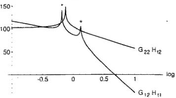
FIG. 5. Graph of the magnitudes of the split-feedback to the intermediate and test masses, 1 G,,H,, 1 and 1 G,H, I. Note the additional crossovers at “*I’ due to the high Q of the normal modes. The feedback parameters used to calculate this graph are the same as those used to calculate Fig. 7.
over about a decade) at the unity gain frequency. As the gain of G,, is decreasing at 40 dB/decade, this requirement can only be satisfied if the gain of H, is increasing at the unity gain frequency. That is, Hr2 should behave as a high- pass filter or differentiator in the region of the unity gain frequency.
Second, at the cross-over frequency, the phase differ- ence between the loop gain of the low-frequency feedback via the intermediate mass (G,,H,, ) and the loop gain of the feedback directly to the test mass (G,,H,) must be < ?r, and preferably be -2?r/3. That is, the magnitudes of these loop gains must not be changing relative to each other at a rate greater than 40 dB/decade. For a servo having a cross- over frequency well below low-Q pendulum normal modes, this condition is equivalent to the requirement that the gain of H,, relative to the gain of H, (i.e., jH,,/H,] ) should not decrease faster than 40 dB/decade at the cross-over frequency. High-Q normal modes, however, will result in additional incorrectly phased cross-overs, as shown in Fig. 5, due to the difference between Gi, and GZ2, and thus lead to instability. This instability can be removed by using lo- cal damping to decrease the Q’s of the normal modes. It may not be possible to completely remove the effects of these normal modes, however, as the phase lag produced by the modes may result in an underdamped transient re- sponse of the servo. As would be expected and will be demonstrated in Sec. IV, the use of local damping to achieve stability becomes even more crucial as the cross- over frequency approaches the normal modes.
5. Closed-loop motion
From Fig. 4(c), the total closed-loop motion of the test mass is given by
X2CL(total) =
xGW’+ (G12J-‘s+X2,e) l+(GH)2 ’
where XGW represents the open-loop displacement due to a gravity wave (the signal) and G12J7J+X2,e represents the open-loop displacement due to seismic noise and general- ized electronic (nonseismic) noise.
[image:4.578.331.509.49.148.2]FIG. 6. Spectrum of seismic displacement noise assumed in the calcula- tion of the rms residual displacement. This spectrum can be generated using 1.5~10-~~.’ m/Hz”’ for f<O.171 Hz, 3.8~ 10-‘“/~g for 0.171 Hz<f<0.636 Hz, 2.8X 10⁻⁹/fo.49 for 0.636 Hz<f<4.59 Hz, and 2.8
x 10-*/f” for f, 4.59 Hz.
noise, and the much smaller-amplitude, high-frequency ( > 100 Hz) motion, due mostly to nonseismic noise, which competes directly with the gravity wave signal. The main effect of the low-frequency motion is to disrupt the destruc- tive interference of the light returning from each of the interferometer arms, thereby increasing the effect of other noise sources such as laser intensity noise and thus decreas- ing the interferometer sensitivity. The effect of these, and other (e.g., laser shot noise), non-servo-electronic noise sources can, in principle, be included in the equivalent in- put displacement noise of the sensor, X,,,, , and thus in
T 4 28
For a “properly designed” servo in which the open- loop high-frequency noise is dominated by the noise at the “front end”, the sensitivity of the interferometer is just given by X,,,. To minimize the effect of gain changes and any “back-end” noise [e.g., current driver noise as repre- sented by ICd in Fig. 4(b)], the gravity wave signal is best monitored at the front end (sensor output) for frequencies above the unity gain frequency, and at the feedback point
(current driver output) for frequencies below the unity gain frequency.
A useful measure of the residual low-frequency mo- tion, the rms motion of the test mass, X2,,, is given by
I ($2 I ‘SF,
1
l/2X 2rms =
jl+WE021zdf ’
where SF,, the spectral density of force noise applied to the intermediate mass due to the seismic motion of the pendu- lum support point, is given by
SF,(W) = pful”+jm~olw/Q1 12sx*(o).
To enable evaluation of X2,, we assumed the seismic noise spectrum shown in Fig. 6, which is similar to that mea- sured recently at JILA.”
IV. RESULTS
The transfer functions of the feedback elements used in the experimental test of the split feedback system’ shown in Fig. 2 are given by
1334 Rev. Sci. Instrum., Vol. 64, No. 5, May 1993
H tl(exp)W =W((l+%) ClfST12) (l+s7,3) (l+m)2),
H n(,,,)(S)=k2(l+Sr21)/((1+Sr22)(1+Sr23)2),
Hi(exp) (S)=k~rjl/((l+sril)(l+Sri2)(1+Sr~3)) H ,(e,,,(S)=k,(l+Sr,1)/((1+Sr~)2(1+Sr,3))r where
kI=4.4X lOi N/m, r1i=2.9x lo5 s,
712=2 s, ~~~=2.2x lo-l4 s, ~,~=4.8x 1O-5 s, k2= 1.0X lo7 N/m, 721=2.2x lo-” s,
722=2.2x 1o-4 s, 723=4.8X 10-s s, ki=1.6X lo3 N/m, ri,=1.5x 10m2 s,
7;2= 1.0x 1o-2 s, ri3=4.7x 1o-3 s,
k,=l.OX lo2 N/m, r,i=4.7~ 10m2 s,
-~~~=4.7X lo-3 S, ~~~=4.7X lo-4 S.
Since some of the filters in the experimental transfer functions were only concerned with reducing the high- frequency gain so as to accommodate the finite amplifier bandwidths and to prevent the excitation of spurious res- onances, the modeling can be simplified by using
kin
Hi(S)=(1+Prii)(1+~r~2) ’
k,( 1 +srrl> Hr(s) = (1 +srr2)2 .
The cross-over frequency can be varied by adjusting the corner frequencies, ( l/rii) and ( 1/7i2), of the integrators in H,, and its dc gain (k,). Stability at the unity gain frequency is obtained by adjusting the corner frequency of the differentiator in H,.
Initially, only the reaction mass was locally damped (i.e., k,=O). Using the feedback parameters listed above, the cross-over frequency is about 0.15 Hz (about a factor of 4 below the lowest normal mode), and the system was stable with well-damped (Q’s-2-10) normal modes. The model indicates that this system would have been stable without the local damping providing the Q’s of the pendu- lums were < 3 x 10². In a high-sensitivity interferometer, however, where the pendulum Q’s must be > - lo’, this relatively low-cross-over-frequency system would not have been stable in the absence of reaction mass damping.
As the cross-over frequency was increased to 0.6 Hz (just above the lowest normal mode), by decreasing the integrator time constants to ril = 6.7 x lo4 s and 7i2 =0.47 s, the prototype system became unstable and stability could only be reattained by using both reaction and intermediate mass damping. This behavior agrees well with the predic- tions of the model. Further, the model predicts that the best damping of the normal modes will occur for k+l
x lo3 N/m and k,--, 1.6X lo3 N/m. These values are sim- ilar to those found experimentally. Note that this system would be stable for arbitrarily high pendulum Q’s.
[image:5.578.87.258.37.151.2]20 log :GHl,
=:,5.
15ot
-1 0 1 ““‘2 lbf
suspension, we believe these techniques could also be used to ensure that the split-feedback remained stable in the presence of other high-Q modes which might couple into the axial motion of the test mass.
ACKNOWLEDGMENTS
This research was supported by the SERC and the University of Glasgow. We would also like to thank fellow group members for useful discussions.
FIG. 7. Graph of a measured and predicted loop gain of the servo con- trolled, balanced two-stage pendulum.
APPENDIX
The predicted rms closed-loop motioh of the test mass is XZmss 1.4~ lo-t2 m. In the proposed high-sensitivity interferometers, such a motion would ensure that only modest intensity stabilization would be required to reduce the sensitivity limit due to laser intensity noise’ below that due to shot noise. To further reduce the rms motion, one would need to increase the low-frequency gain and thus the servo bandwidth. This may not be possible, however, as parasitic high-frequency mechanical resonances might cause the servo to be unstable.
The open-loop gain was measured for a system having r1 I = 1.4X 10’ s, r12 = 1 s, and k,= 1 X lo3 N/m (cross-over frequency - 0.3 Hz). This system is in principle unstable if the pendulums have high Q ’s but was stable in practice due to the relatively low Q ’s of the pendulums in the prototype system. The loop gain was measured, as indicated earlier, by applying sine-wave signals of known amplitude and fre- quency to the PZT on which the reference mirror was mounted, and comparing the closed-loop displacement with the applied displacement. Applied displacements of several microns were used to allow measurements to be made at adequate signal-to-noise ratio. The measurements and the predicted open-loop gain are shown in Fig. 7. The predicted gain was calculated assuming Q,=200, but it should be noted that the shape of this curve is relatively insensitive to the value of Q, , and thus the agreement between experiment and theory is remarkably good.
V. DISCUSSION
We have experimentally demonstrated the use of a split feedback servo system for the control of the bottom mass in a balanced two-stage pendulum vibration isolation sys- tem. The importance of local damping of the intermediate and reaction masses in stabilizing the servo, particularly for high-Q pendulum suspensions, has been highlighted. We have also presented a block diagram which accurately describes this multiple input, multiple output servo system, and could be used to determine the effect of noise added by the servo electronics.
While this article has only been concerned with the damping and control of the simple-pendulum modes of the
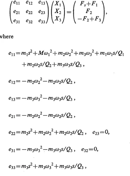
The solution of the coupled equations of motion of the masses in a servo-controlled balanced two-stage pendulum will be outlined in this Appendix. The definition of various variables used in the body of the paper, e.g., Gij and T,, will also be given here.
The Laplace transformed equations of motion of the two-stage balanced pendulum shown in Fig. 2 are
where
ell=mlsZ+Mwl”+m2w22+m3w32+mlwls/Q, + m2wiQ2 + w&Q3 ,
q2= -m2q2-m2w2dQ2,
e13= -m3q2-m3w3s/Q3,
e21 = - m2w22 - m2w2s/Q2 ,
e22 = m22 + m2q2 +qwg/Q2 , e23 = 0,
Xlc2,3) is the displacement of the intermediate (test, reac- tion) mass, I;1(3) is the force applied to the intermediate
[image:6.576.301.520.318.615.2]x
loL=w33(Fs+F19 + (e13e22-el2e339F2-el3e22F3
d&f 9
X 2OL =
--e21e33(Fs+F19
+~~~~~~~~~~~~~~~~~~~~~~~~~~~~~~~~~
de&/ ,X 3oL= --22e31(Fs+Fl) -
(elle22--12e2l--el2e319F2+
(elle22-wdF3 d&f7
where the determinant of the coefficient matrix, [e], with no feedback, is given by
detnf=elle22e33-e12e21e33-e13e22e31 .
Defining the mechanical responses, Gi/, by Gij-XjoL/Fi, where Fk=Q for k#i and F,=O, yields
G12= -e2res3/det,J.,
G22=(e11e33-e13e21--e13e319/detnf,
G32 = etse21/det,f .
To determine the closed-loop (CL) transfer functions let F,=-HH,Xl--HtlX2, F2=-HaX2, and F3=-H,X3. The closed-loop response is then given by
x lcL=
(e22+&9 (e33+Hr9Fs
det j-b,
x2,=
-+l(e33+Hr9Fs
detfb ’
x3cL=
-(e22e31+Hn(e21+e319)Fs
det fb
f
where the determinant of the coefficient matrix, [e], with feedback, is given by
detfb= (ell+Hi)
(e22+Ha9 (e33+Hr9
-
(e12+f&19e21(e33+Hr9
---H&w21--e13(e~+Ht29e31
.The coefficients which relate the closed-loop motion of the intermediate and reaction masses to that of the test mass are thus given by
T21 -X~CL./&L= -
(e22+&9/e21
x3,, e22e31+Ha(e21+e319 Tut---=
X2CL e21 (es3 +&J ’
’ W. Winkler, in The Detection of Gravitatonal Waves, edited by D. G. Blair (Cambridge U. P., Cambridge 1991), p. 269; R. W. P. Drever, ibid. p. 306; J. Hough et aL, ibid., p. 329.
IN. A. Robertson, ibid., p. 353.
3 J. Hough et aL, “Proposal for a Joint German-British Interferometric Gravity Wave Detector” (Max-Planck-Institut fur Quantenoptik MPQ147, 1989); K. Danzmann et aL, in Springer Lecture Notes in Physics (in press).
4R. E. Vogt, R. W. P. Drever, F. J. Raab, K. S. Thome, and R. Weiss, A Laser Interjkometer Gravitational- Wave Observatory (LIGO) (Cali- fornia Institute of Technology, CA, 1989)
‘A. Giazotto, A. Brillet et aL, The VIRGO Project (Instituto Nazionale di Fisica Nucleare, Sezione di Pisa, 1990).
6C. A. Cantley, J. Hough, N. A. Robertson, and R. J. S. Greenhalgh, Rev. Sci. Instrum. 63, 2210 (1992).
’ N. A. Robertson et al., in Proceedings of the F$h Marcel Grossmann Meeting on General Relativity, edited by D. G. Blair and M. J. Buck- ingham, (World Scientific, Singapore, 1989), p. 1775.
’ C. A. Cantley, Ph.D. thesis, University of Glasgow ‘( 199 1).
9M. Stephens, P. Saulson, and J. Kovalik, Rev. Sci. Instmm. 62, 924 (1991).
lo D Shoemaker, R. Schilling, L. Schnupp, W. Winkler, K. Maischberger, and A. Rudiger, Phys. Rev. D 38, 423 (1988).
“J. E. Faller, P. L Bender, and R. T. Stebbins, ‘Low Frequency Isola- tion Systems for Gravitational Wave Interferometers,” Joint Institute for Laboratory Astrophysics, unpublished.