This is a repository copy of
A tunable quantum optical filter using the Fano effect in a
waveguide
.
White Rose Research Online URL for this paper:
http://eprints.whiterose.ac.uk/139127/
Version: Submitted Version
Article:
Foster, A.P. orcid.org/0000-0002-5817-0008, Hallett, D., Iorsh, I.V. et al. (9 more authors)
(Submitted: 2018) A tunable quantum optical filter using the Fano effect in a waveguide.
arXiv. (Submitted)
© 2018 The Author(s). For reuse permissions, please contact the Author(s).
[email protected] https://eprints.whiterose.ac.uk/
Reuse
Items deposited in White Rose Research Online are protected by copyright, with all rights reserved unless indicated otherwise. They may be downloaded and/or printed for private study, or other acts as permitted by national copyright laws. The publisher or other rights holders may allow further reproduction and re-use of the full text version. This is indicated by the licence information on the White Rose Research Online record for the item.
Takedown
If you consider content in White Rose Research Online to be in breach of UK law, please notify us by
A.P. Foster, ∗ D. Hallett, I.V. Iorsh, S.J. Sheldon, M.R. Godsland, B. Royall, E. Clarke,3 I.A. Shelykh,2, 4 A.M. Fox,1 M.S. Skolnick,1, 2 I.E. Itskevich,5 and L.R. Wilson1,†
1Department of Physics and Astronomy, University of Sheffield, Sheffield S3 7RH, UK
2ITMO University, St. Petersburg 197101, Russia
3EPSRC National Epitaxy Facility, University of Sheffield, Sheffield S1 3JD, UK
4Science Institute, University of Iceland, Dunhagi 3, IS-107, Reykjavik, Iceland
5School of Engineering and Computer Science, University of Hull, Hull HU6 7RX, UK
(Dated: November 22, 2018)
A strong optical nonlinearity arises when coherent light is scattered by a semiconductor quantum dot (QD) coupled to a nano-photonic waveguide. We exploit the Fano effect in such a waveguide to control the phase of the quantum interference underpinning the nonlinearity, demonstrating a tunable quantum optical filter which converts a coherent input state into either a bunched, or antibunched non-classical output state. We show theoretically that the generation of non-classical light is predicated on the formation of a two-photon bound state due to the interaction of the input coherent state with the QD. Our model demonstrates that the tunable photon statistics arise from the dependence of the sign of two-photon interference (either constructive or destructive) on the detuning of the input relative to the Fano resonance.
The generation of non-classical light is a fundamen-tal requirement for the operation of integrated quantum photonic devices. For example, a single photon input is a prerequisite for linear optical quantum computing [1], whilst the use of NOON states may enable sensing with Heisenberg-limited precision in the field of tum metrology [2, 3]. Photon emission by few-level quan-tum systems such as quanquan-tum dots (QDs) is commonly used to address this challenge, enabling the generation of single- [4] and two-photon [5] states, as well as the creation of entangled states on-chip [6].
Photon number-state filtering of a coherent input rep-resents a markedly different approach, which has the po-tential to generate both bunched, and antibunched non-classical light on demand. A coherent input state can be considered as a weighted sum of different number states [7]. Selective enhancement or suppression of spe-cific number-states therefore enables conversion of the classical input into a quantum output state. This was first demonstrated in a semiconductor device by using the anharmonicity of the levels of a strongly-coupled, QD-cavity system to filter one- or two-photon states from a coherent input state [8–10]. More recently, photon-number-dependent constructive or destructive quantum interference in weakly-coupled QD-cavity devices has been used to achieve the same goal [11–13].
The Fano effect presents an intriguing mechanism for tunable number-state filtering [14, 15], which remains un-explored experimentally. A Fano resonance arises due to interference between a discrete transition and a back-ground continuum [16], with the maxima and minima of the spectral lineshape being the result of constructive and destructive interference respectively. The change in in-terference with detuning of the coherent input relative to the Fano resonance can be used to enable tunable number-state filtering in a suitably engineered device.
To demonstrate this, we employ an integrated quantum photonic device comprising a single quantum two-level system, namely a QD, coupled to a single-mode waveg-uide. In an ideal waveguide, single photons resonant with a QD transition are fully reflected, due to destructive in-terference in the transmission direction between photons scattered from the QD and the driving laser field [17]. This results in a symmetric spectral profile in transmis-sion, as shown in Fig. 1a. However, a real waveguide can exhibit Fabry-P´erot (F-P) modes arising from reflections within the device. The phase of the laser field is then de-pendent on the detuning relative to the F-P modes, and a Fano resonance will be observed if the QD transition is detuned from a F-P mode [18, 19], as shown in Fig. 1b.
For the output photon statistics, the behaviour of two-photon states is of importance. It has been predicted for an ideal waveguide that, on resonance with the QD tran-sition, two-photon states are preferentially transmitted (a manifestation of the nonlinear interaction between pho-tons and the QD at the single photon level), and the out-put state is bunched [17]. Similarly, bunching will occur when the input is detuned to the destructive interference regime of a Fano resonance. Notably, when the input is detuned to the constructive interference regime, the possibility arises of the output state being antibunched [15]. Such a non-classical output state, tunable across the Fano resonance, has yet to be demonstrated for an integrated quantum photonic device.
In this Letter, we demonstrate a tunable quantum op-tical filter using an integrated device comprising a sin-gle QD coupled to a sinsin-gle-mode nano-photonic waveg-uide. We inject a tunable, coherent laser field into the waveguide, and observe a Fano resonance in trans-mission. We show that the transmitted state photon statistics are antibunched when resonant with the Fano maximum and bunched at the Fano minimum, evidence
2
FIG. 1. (a) Calculated single photon transmission for a waveg-uide containing a single QD (upper schematic), as a function of the input detuning relative to the QD transition. δis the QD transition linewidth. (b) Calculated transmission for a waveguide containing a single QD and supporting F-P modes due to partially reflective interfaces (PRIs) in the waveg-uide (upper schematic). The QD transition is either resonant (dashed red line) or non-resonant (dotted blue line) with the F-P mode. The transmission for the same waveguide without a QD is shown by a black solid line for reference. FSR stands for free spectral range.
of tunable number-state filtering. The tuning can be achieved either by changing the laser wavelength or by electrically Stark-shifting the QD transition, demonstrat-ing control of the photon statistics locally, on-chip. We model the system and show that the formation of a two-photon bound (frequency entangled) state is critical to observe number-state filtering. Furthermore, antibunch-ing is only achieved in the case of destructive interference of two-photon product states and bound states, which becomes possible due to the Fano resonance.
Fig. 2a shows a scanning electron microscope image of our quantum optical filter, which was fabricated within a 170nm thick, GaAs p-i-n membrane. InGaAs self-assembled QDs were embedded in the intrinsic region of the membrane and could be Stark tuned by applica-tion of a bias to the diode. (Details of the wafer, de-vice design and experimental procedures can be found in the Supplemental Material [20].) The device consists of a suspended single-mode photonic crystal waveguide (PhCWG) with nanobeam waveguides attached to ei-ther end. The waveguides are terminated with semi-circular Bragg gratings which enable vertical in- and out-coupling of light. The PhCWG has a photonic band edge at∼916nm, which was measured using waveguide-transmitted, non-resonant photoluminescence (PL) from the ensemble of QDs. The PL was excited in one Bragg coupler and detected from the other coupler, and is shown in Fig. 2b. F-P modes are revealed through os-cillations in the transmitted intensity. The mode spacing of∼2nm suggests that the dominant reflection occurs at the two Bragg coupler-nanobeam waveguide interfaces.
QDs emitting in spectral proximity to the PhCWG band edge experience a slow light-induced Purcell
en-FIG. 2. (a) Scanning electron microscope image of the nano-photonic device. The triangle shows the approximate location of the QD studied here, situated in a slow light PhCWG. (b) Device transmission probed using high power non-resonant PL (500µW at 780nm). The black arrow indicates the lo-cation of the photonic band edge. (c) Resonant photolumi-nescence excitation spectrum for the trion state of the QD located in the PhCWG (circles), with spectral position given by the red dashed arrow in (b). The background laser scatter has been subtracted. The line is a Voigt fit to the data.
hancement [21]. The Purcell enhancement increases the QD exciton decay rate and consequently reduces the im-pact of dephasing on the coherence of the exciton emis-sion. It also increases the β-factor which characterises the optical coupling strength between the QD and the waveguide mode [22], with a value as large as 0.98 pre-viously reported [23]. In this regime, the QD may be considered as a ‘1D atom’, coupling almost uniquely to the single mode of the waveguide.
Resonance fluorescence measurements, with excitation from above the QD and collection from an outcoupler, were used to locate a suitable single QD in the PhCWG. Fig. 2c shows the resonant photoluminescence excitation spectrum for such a QD, obtained by scanning a narrow-band continuous wave laser across the QD transition. Its wavelength of 915.045nm lies within 1nm of the PhCWG band edge. The transition is likely to be a charged trion, as we typically observe fine-structure splitting for the QD neutral exciton in this sample [24]. In a separate mea-surement using resonant pulsed excitation (not shown), the lifetime of the trion state was found to be 150±30ps, which corresponds to a radiatively-limited linewidth of 4-6µeV. We measured an ensemble lifetime of 750ps for
QDs in the bulk of the sample and therefore estimate a Purcell factor of∼5. The linewidth in Fig. 2c is broad-ened to 15µeV due to spectral wandering. We note that
the QD could be Stark-tuned over more than 100µeV,
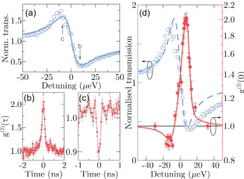
[image:3.612.317.561.51.156.2] [image:3.612.54.298.51.178.2]FIG. 3. (a) Measured waveguide transmission as a function of laser-trion detuning (circles), normalised to the transmis-sion measured at large detuning. The solid line is a Breit-Wigner-Fano fit to the data. (b,c) Second order autocorre-lation function g(2)(τ) at a detuning of (b) +9µeV and (c) –9µeV, as indicated in (a). The data has been normalised to the value ofg(2)(τ) at long time delay. Error bars correspond to the square root of the coincidence counts in each time bin. (d)g(2)(0) (red filled circles) and normalised waveguide trans-mission (blue open circles) as a function of laser-trion detun-ing. Error bars originate from fitting of the fullg(2)(τ) data. Solid and dashed lines represent the result of modelling (see text for details). The axis forg(2)(0) is logarithmic.
which was controlled by changing the laser wavelength [25]. The transmission is normalised to the background level measured in the absence of the laser-trion interac-tion. (This was achieved by electrical tuning of the QD transition far out of resonance with the laser.) A char-acteristic dispersive Fano lineshape is observed, due to interference between photons scattered from the QD and the driving laser field. Note that the minimum transmis-sion is as small as 40%, which is evidence for the strong interaction between single photons and the QD.
Now we consider the photon statistics of the trans-mitted field. Using a Hanbury Brown-Twiss setup, the second order autocorrelation function g(2)(τ) was mea-sured as a function of laser-trion detuning. The con-volved instrument response time was 80ps. In Fig. 3b-c we compare the normalised g(2)(τ) histograms for laser-trion detunings of +9µeV and –9µeV, which correspond
to the Fano transmission minimum and maximum respec-tively. At a detuning of +9µeV substantial bunching
is observed, with g(2)(0)=2.02±0.07. After deconvolu-tion with the instrument response funcdeconvolu-tion, we obtain a g(2)(0) value of 2.20±0.08, which is greater than the ther-mal classical limit. In sharp contrast, clear antibunching is measured at a detuning of –9µeV, demonstrating the
successful filtering out of two-photon states from the co-herent input state. To demonstrate the tunability of our
device, Fig. 3d shows the measured g(2)(0) as a func-tion of the laser-trion detuning, covering the full spectral width of the Fano resonance. From negative to positive detuning, a dispersive lineshape is seen in the photon statistics, whilst at large detuning the photon statistics are those of a coherent state, withg(2)(0) equal to unity. Thus, we have demonstrated that the photon statistics can be manipulated by means of number-state filtering using the detuning as the single control parameter. (See the Supplemental Material for measurements where the Stark shift of the QD transition was used as the control parameter.)
Understanding of the output photon statistics requires consideration of two kinds of two-photon states, namely (separable) product states and (frequency entangled) bound states [26–28]. We note that for two-photon prod-uct states, constrprod-uctive or destrprod-uctive interference at the Fano resonance follows that of single-photon states. This implies that in the absence of bound states, a coherent input would always result in a coherent output. Obser-vation of photon number-state filtering must therefore be related to the formation of the bound states. Indeed, the bound states have been shown to explain bunching [28]. However, their presence alone is insufficient to explain the observed antibunching. To account for the antibunching, it is also necessary to consider interference between two-photon product states and bound states, as our following analysis shows. In particular, we identify the conditions under which antibunching becomes possible, and the role of F-P modes in this.
To gain the necessary insight, we model the system using the input-output formalism [15]. Theg(1) andg(2) two-time correlation functions are given by
g(1)(t, t′) = 1 t2 0
hα|cˆ†out(t′)ˆcout(t)|αi, (1)
g(2)(t, t′) = hα|ˆc † out(t)ˆc
†
out(t′)ˆcout(t′)ˆcout(t)|αi
g(1)(t, t)g(1)(t′, t′) , (2)
where t0 is the bare waveguide transmission amplitude in the absence of the QD, evaluated at the wavelength of the QD transition. The input coherent state is|αi, whilst ˆ
cout are the output field annihilation operators. In the
low power, stationary limit (t → ∞), with β = 1 and neglecting QD dephasing, we find that
g(1)= (˜δ+ tanφ) 2
(1 + ˜δ2) =|t1|
2, (3)
g(2)(0) = 1
|t1|4
t1t1+ e 2iφ
T0(1 + ˜δ2)
2
(4)
= 1 + 1
T02(˜δ+ tan(φ))4+
2 cos 2φ
T0(˜δ+ tan(φ))2, (5)
[image:4.612.54.297.50.229.2]4
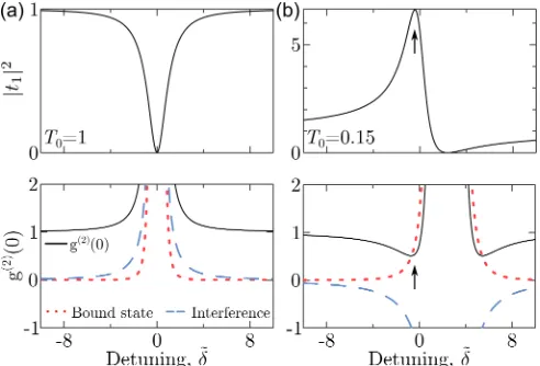
FIG. 4. Theoretical transmission |t1|2 (upper panels) and
g(2)(0) (lower panels - solid black lines) as a function of the
detuning between the laser and the QD transition, for a bare waveguide transmission of (a)T0= 1 and (b)T0= 0.15.
An-tibunching can clearly be seen at a detuning corresponding to the Fano maximum, indicated by the arrows. Also shown are the contributions to theg(2)(0) from the two-photon bound state (red dotted lines) and the interference between two-photon product and bound states (blue dashed lines). The contribution tog(2)(0) from the two-photon product state is equal to unity for all detunings (see Eq. 4).
denotes the transition decay rate. The single photon transmission amplitude is given by t1, T0 = t2
0 and φ= tan−1(−p
1−t2
0/t0). Note thatφ is related to the detuning of the QD transition from the F-P modes. The full time-dependent expressions, also accounting for QD dephasing and non-unity β-factor, can be found in the Supplemental Material.
We fit the model to the experimentalg(2)(0) data, then use the same best-fit parameters to evaluate the nor-malised transmission using the equation forg(1). The re-sulting fits are shown in Fig. 3d, showing very good agree-ment with the experiagree-mental results for both the transmis-sion and the g(2)(0). The model clearly reproduces the most significant feature of the measured data, namely the generation of an antibunched transmitted field at nega-tive detuning in addition to bunching at posinega-tive detun-ing. (See the Supplemental Material for more details of the fitting procedure.)
We now consider the physical process underpinning the quantum optical filter, using Eqs. (4) and (5). Eq. (4) reveals interference between two-photon product states and two-photon bound states [15] (the first and the sec-ond term in the modulus squared, respectively). The first two terms in Eq. (5), obtained after evaluation of the modulus, represent the bare contributions tog(2)(0) from the product states (the unity term) and the bound states, respectively, and the third term describes interference be-tween the two-photon states. Analysis of Eqs. (4) and (5) leads to several immediate conclusions. First, it is clear
that the formation of the bound state is critical for the generation of non-classical light, as in its absenceg(2)(0) equals unity. Secondly, the bound state term in Eq. 5 is positively valued, and the first two terms combined would only lead tog(2)(0)≥1, i.e. either a coherent or bunched output state. Evidently, antibunching can only arise in the case of destructive two-photon interference, for which the third term in Eq. 5 is negative. The latter is possible in the case whenφ < π/4 and hence for bare waveguide transmissionT0 <0.5. One should note that access to this regime in an otherwise ideal waveguide is enabled by the presence of F-P modes (whose presence also gives rise to the Fano effect.)
This is illustrated in Fig. 4, in which we plot the trans-mission|t1|2=g(1) andg(2)(0), for representative values ofT0= 1 andT0= 0.15. T0= 1 corresponds to a QD in a perfectly transmissive waveguide, while at T0 = 0.15 a QD is significantly off-resonant with an F-P mode. When T0 = 1, both the bound state contribution and the interference term are positive, and bunching is pre-dicted across the whole range of detuning in Fig. 4a, in agreement with Ref. [15]. However, for T0 = 0.15 the interference term is negative, and where it outweighs the contribution from the bound state, antibunching occurs. Notably, one expects antibunching at the Fano transmis-sion maximum, as observed experimentally. (This is indi-cated by arrows in Fig. 4b). In particular, forT0= 0.15, g(2)(0) is expected to be as low as 0.5 at the Fano max-imum; furthermore, g(2)(0)→ 0 asT0 →0 in the ideal case scenario. Physically, the Fano maximum favours transmission of single photons from the coherent input. At the same time, the contribution to the output from the two-photon product states is suppressed due to de-structive interference with the bound states, resulting in antibunching.
is achieved by controlling the detuning of the laser rela-tive to the Fano resonance, either by changing the laser wavelength, or locally, using the quantum-confined Stark effect. Notably, antibunching is only observed due to the presence of the Fano resonance. We have shown theo-retically that the non-classical output state is critically dependent on the formation of a two-photon bound state due to interaction of the coherent input with the QD, and that control over the photon statistics arises due to the change between constructive and destructive two-photon interference at the extrema of the Fano resonance.
This work was supported by EPSRC Grant No. EP/N031776/1 and by Megagrant 14.Y26.31.0015 of the Russian Federation. I.V.I. thanks D. Kornovan for valu-able discussions. Data supporting this study are openly available from the University of Sheffield repository [29].
[1] P. Kok, W. J. Munro, K. Nemoto, T. C. Ralph, J. P. Dowling, and G. J. Milburn, Rev. Mod. Phys. 79, 135
(2007).
[2] M. M¨uller, H. Vural, C. Schneider, A. Rastelli, O. G. Schmidt, S. H¨ofling, and P. Michler, Phys. Rev. Lett.
118, 257402 (2017).
[3] A. J. Bennett, J. P. Lee, D. J. P. Ellis, T. Meany, E. Mur-ray, F. F. Floether, J. P. Griffths, I. Farrer, D. A. Ritchie, and A. J. Shields, Science Advances2, e1501256 (2016).
[4] N. Somaschi, V. Giesz, L. De Santis, J. C. Loredo, M. P. Almeida, G. Hornecker, S. L. Portalupi, T. Grange, C. Ant´on, J. Demory, C. G´omez, I. Sagnes, N. D. Lanzillotti-Kimura, A. Lema´ıtre, A. Auffeves, A. G. White, L. Lanco, and P. Senellart, Nature Photonics
10, 340 (2016).
[5] T. Heindel, A. Thoma, M. von Helversen, M. Schmidt, A. Schlehahn, M. Gschrey, P. Schnauber, J.-H. Schulze, A. Strittmatter, J. Beyer, S. Rodt, A. Carmele, A. Knorr, and S. Reitzenstein, Nature Communications 8, 14870
(2017).
[6] R. J. Young, R. M. Stevenson, P. Atkinson, K. Cooper, D. A. Ritchie, and A. J. Shields, New Journal of Physics
8, 29 (2006).
[7] M. Fox,Quantum Optics: An Introduction(Oxford Uni-versity Press, 2006).
[8] A. Faraon, I. Fushman, D. Englund, N. Stoltz, P. Petroff, and J. Vuckovic, Nature Physics4, 859 (2008).
[9] A. Reinhard, T. Volz, M. Winger, A. Badolato, K. J. Hennessy, E. L. Hu, and A. Imamoglu, Nature Photonics
6, 93 (2011).
[10] K. M¨uller, A. Rundquist, K. A. Fischer, T. Sarmiento,
K. G. Lagoudakis, Y. A. Kelaita, C. S´anchez Mu˜noz, E. del Valle, F. P. Laussy, and J. Vuˇckovi´c, Phys. Rev. Lett.114, 233601 (2015).
[11] A. J. Bennett, J. P. Lee, D. J. P. Ellis, I. Farrer, D. A. Ritchie, and A. J. Shields, Nature Nanotechnology11,
857 (2016).
[12] H. J. Snijders, J. A. Frey, J. Norman, H. Flayac, V. Savona, A. C. Gossard, J. E. Bowers, M. P. van Exter, D. Bouwmeester, and W. L¨offler, Phys. Rev. Lett.121,
043601 (2018).
[13] L. De Santis, C. Ant´on, B. Reznychenko, N. Somaschi, G. Coppola, J. Senellart, C. G´omez, A. Lemaˆıtre, I. Sagnes, A. G. White, L. Lanco, A. Auff`eves, and P. Senellart, Nature Nanotechnology12, 663 (2017),
ar-ticle.
[14] A. Ridolfo, O. Di Stefano, N. Fina, R. Saija, and S. Savasta, Phys. Rev. Lett.105, 263601 (2010).
[15] S. Xu and S. Fan, Phys. Rev. A94, 043826 (2016).
[16] M. F. Limonov, M. V. Rybin, A. N. Poddubny, and Y. S. Kivshar, Nature Photonics11, 543 (2017).
[17] D. E. Chang, A. S. Sørensen, E. A. Demler, and M. D. Lukin, Nature Physics3, 807 (2007).
[18] A. Javadi, I. S¨ollner, M. Arcari, S. L. Hansen, L. Midolo, S. Mahmoodian, G. Kirsanske, T. Pregnolato, E. H. Lee, J. D. Song, S. Stobbe, and P. Lodahl, Nature Commu-nications6, 8655 (2015).
[19] D. L. Hurst, D. M. Price, C. Bentham, M. N. Makhonin, B. Royall, E. Clarke, P. Kok, L. R. Wilson, M. S. Skol-nick, and A. M. Fox, Nano Letters18, 5475 (2018).
[20] See Supplemental Material at [URL] for details concern-ing the sample design, experiment setup and additional results, and input-output modelling of the device. The Supplemental Material also contains an additional refer-ence, Ref. [30].
[21] S. Hughes, Opt. Lett.29, 2659 (2004).
[22] V. S. C. Manga Rao and S. Hughes, Phys. Rev. B75,
205437 (2007).
[23] M. Arcari, I. S¨ollner, A. Javadi, S. Lindskov Hansen, S. Mahmoodian, J. Liu, H. Thyrrestrup, E. H. Lee, J. D. Song, S. Stobbe, and P. Lodahl, Phys. Rev. Lett.113,
093603 (2014).
[24] D. Hallett, A. P. Foster, D. L. Hurst, B. Royall, P. Kok, E. Clarke, I. E. Itskevich, A. M. Fox, M. S. Skolnick, and L. R. Wilson, Optica5, 644 (2018).
[25] It is also possible to control the detuning by Stark-shifting the energy of the QD transition, as shown in the Supplemental Material.
[26] J.-T. Shen and S. Fan, Phys. Rev. A76, 062709 (2007).
[27] J.-T. Shen and S. Fan, Phys. Rev. Lett. 98, 153003
(2007).
[28] H. Zheng, D. J. Gauthier, and H. U. Baranger, Phys. Rev. A82, 063816 (2010).
[29] https://doi.org/10.15131/shef.data.7360988.
[30] S¸. E. Kocaba¸s, E. Rephaeli, and S. Fan, Phys. Rev. A