Invited Article: CO2
laser production of fused silica fibers for use in
interferometric gravitational wave detector mirror suspensions
A. Heptonstall,1,2,a)M. A. Barton,1A. Bell,2G. Cagnoli,3C. A. Cantley,2D. R. M. Crooks,2 A. Cumming,2A. Grant,2G. D. Hammond,2G. M. Harry,4J. Hough,2R. Jones,2D. Kelley,4 R. Kumar,2I. W. Martin,2N. A. Robertson,1,2S. Rowan,2K. A. Strain,2K. Tokmakov,2and M. van Veggel2
1LIGO Laboratory, California Institute of Technology, Pasadena, California 91125, USA
2SUPA, Institute for Gravitational Research, University of Glasgow, Glasgow G12 8QQ, United Kingdom 3Istituto Nazionale di Fisica Nucleare, Sezione di Firenze, Sesto Fiorentino I-50019, Italy
4LIGO Laboratory, Massachusetts Institute of Technology, Cambridge, Massachusetts 02139, USA
(Received 13 September 2010; accepted 6 November 2010; published online 21 January 2011)
In 2000 the first mirror suspensions to use a quasi-monolithic final stage were installed at the GEO600 detector site outside Hannover, pioneering the use of fused silica suspension fibers in long baseline interferometric detectors to reduce suspension thermal noise. Since that time, development of the production methods of fused silica fibers has continued. We present here a review of a novel CO2
laser-based fiber pulling machine developed for the production of fused silica suspensions for the next generation of interferometric gravitational wave detectors and for use in experiments requiring low thermal noise suspensions. We discuss tolerances, strengths, and thermal noise performance requirements for the next generation of gravitational wave detectors. Measurements made on fibers produced using this machine show a 0.8% variation in vertical stiffness and 0.05% tolerance on length, with average strengths exceeding 4 GPa, and mechanical dissipation which meets the requirements for Advanced LIGO thermal noise performance.© 2011 American Institute of Physics. [doi:10.1063/1.3532770]
I. INTRODUCTION
One of the limiting sources of noise in interferometric gravitational wave detectors is the thermally driven motion of the mirrors and their suspensions. According to the fluctuation-dissipation theorem,1–5 thermal noise may be reduced at detection band frequencies by use of ultralow dissipation materials. The power spectral density of thermally induced displacement noise for a pendulum, at frequencies well aboveresonance, may be written as
Sx(ω)=
4kBTω2 0
mω5 φ(ω), (1)
whereωis the angular frequency,mis the suspended mass,
T is the temperature, ω0 is the pendulum angular resonant
frequency, kB is the Boltzmann constant, and φ(ω) is the
pendulum loss angle. Fused silica is one such low dissipation material suitable for interferometric gravitational wave detectors.6–11 Dissipation in fused silica is several orders of magnitude lower than in metals.12–14
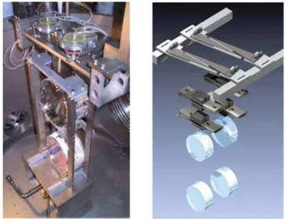
Friction in the joints of the mirror suspensions also con-tributes to detection band thermal noise.15GEO600 is the first
detector to use a quasi-monolithic final stage in the mirror suspensions to reduce this friction.16 Figure1(a)shows one
of the GEO600 triple suspensions. Attachment blocks are hydroxide-catalysis bonded to the GEO600 optics.16–19 The
optic is then suspended using four flame-pulled fused silica fibers that are gas-welded to the attachment blocks.20
a)Electronic mail: heptonstall_a@ligo.caltech.edu.
Following the success in GEO600, where a total of 20 fibers have suspended the optics for over eight years with no evidence of unexpected problems,21 planned upgrades to the LIGO and Virgo detectors will include installation of quasi-monolithic final stage suspensions.22,23 Figure1(b)shows a
SOLIDWORKSR (Ref. 24) rendering of an Advanced LIGO
quadruple mirror suspension. Thermoelastic damping25–27 (φ
t), frequency dependent
bulk dissipation11,28(φ
b), and dissipation in the surface
layer29 (φ
s) all contribute to the total loss angle of the
pen-dulum. The loss of the pendulum mode is reduced by the di-lution factor (D), given by the ratio of energy stored in lifting the mass against gravity to energy stored in flexing the fiber. The total loss of the pendulum mode may be written as
φ(ω)=D(φt+φb+φs). (2)
For thin fibers bulk loss is negligible compared to dissi-pation from the lossy surface layer.11,30,31 Each of the other
components is dependent on the diameter of the flexure point, with dilution also being dependent on fiber length.
The average fiber diameter sets the frequency for certain other modes of oscillation of the suspension. The mode in which the test mass moves vertically up and down is known as the vertical bounce mode and the frequency of this affects coupling of vertical noise into the detector.32,33The strength
of the fiber ultimately limits how low the vertical bounce fre-quency can be made. The modes in which the masses above and below the fibers stay approximately stationary while the fibers oscillate are known collectively as the violin modes since the fibers move in a similar manner to the strings of a
FIG. 1. (Color) Gravitational wave detector mirror suspensions. (a) GEO600 triple suspension. (b)SOLIDWORKSrendering of an Advanced LIGO quadru-ple suspension.
stringed instrument. The fiber diameter also sets the frequency of fiber violin modes. For all current interferometric detectors, the lowest frequency violin modes occur in the detection band of the interferometer, where the small motions of the test mass they cause must be notched out of the data. It is preferable to have the violin mode frequencies as high as possible by keep-ing the fiber diameter small.
For a mass suspended close to the center of mass, the dilution effect is given by34
D= 1
L
Yπr4
4T , (3)
whereY is the Young’s modulus of the fibers,r is the radius of the fibers,Lis the fiber length, andT is the tension in each fiber. The dissipation in the surface layer may be modeled as29
φs =8h
2rφsurface, (4)
wherehis the thickness of the lossy surface layer andφsurface
is the loss angle of this layer. The thermoelastic loss for a fiber under tension is given by the nonlinear thermoelastic theory27
φt=
Y T
ρC
ωτ
1+(ωτ)2 α−β mg
Yπr2
2
, (5)
whereρis the density,αis the thermal expansion coefficient,
Cis the specific heat capacity, andβis the fractional change in Young’s modulus with temperature. The characteristic time for heat transfer across a cylindrical fiber,τ, is given by
τ = ρCd2
4.32πκ, (6)
whereκis the thermal conductivity.
From Eq.(5), we see that for a given mass, it is possi-ble to cancel the thermoelastic contribution completely by us-ing a particular fiber diameter. For a 40 kg mass suspended on four fibers, this corresponds to approximatelyr =410μm depending on the exact values of the material properties. From Eq.(3), it can be seen that the dilution effect increases as the fiber diameter decreases and it is of interest to note that while the thermoelastic loss may be canceled for a given diameter
3mm stock material from which fiber is pulled
First neck
820um diameter section for cancellation of thermoelastic loss
Second neck
[image:2.612.327.547.47.306.2]390um diameter central section
FIG. 2. Diagram showing the profile of one end of a dumbbell shaped fiber.
of fiber, the dilution effect is reduced since the ends of the fiber are thicker. However, there is a minima in the total loss for this diameter, giving a lower thermal noise.
The baseline design for Advanced LIGO is a dumbbell design of fiber,35,36 where the diameter of the flexure points
is set to cancel thermoelastic noise, while the middle of the fiber is thinned down to reduce the bounce frequency (<10 Hz) and increase the first violin mode resonance (>500 Hz). Figure2 shows a schematic of the varying diameter profile of a dumbbell shaped fiber. The fiber pulling system must be capable of creating this varying diameter shape.
Fiber diameter, length, and placement also affect the pitch, yaw, and roll of the mirror, altering the coupling of noise into the horizontal direction. Modeling of the Advanced LIGO quadruple suspension32,33,37 sets a required tolerance of 2.8% for the vertical stiffness of the fiber, and a position-ing of the flexure point of approximately 0.1 mm parallel to the optical axis and 1 mm vertically. In addition to this the vi-olin mode frequencies, which must be notched out of control systems, should be kept as close together as possible, approxi-mately within 1 Hz of each other. For the first violin mode this gives a fiber length tolerance of 1.2 mm, and for the second violin mode, a length tolerance of 0.6 mm.
The static stress on the fibers will be 0.8 GPa and it is a technical requirement that the failure point of the fibers be at least three times this value. The suspension is constrained in a structure that prevents the fibers stretching by more than the equivalent of an additional 20% loading.
Silica fibers have been produced by a variety of methods,30,31,38–40 though all follow a common theme. The thin fibers are drawn from a thicker stock material that is heated until molten and then pulled. Techniques for produc-ing fused silica fibers by hand in a hydrogen–oxygen flame have existed for some time.38 While it is possible to
[image:2.612.70.277.52.211.2]required to meet the consistency requirements of gravitational wave detector mirror suspensions.
The fibers used in the GEO600 mirror suspensions were produced using an automated pulling machine, using a hydrogen–oxygen flame to heat the silica until molten. The machine used a “heat then pull” method whereby the total amount of silica required for the fiber was heated, then the flame was removed and the fiber was pulled by two chain-driven arms mounted on linear bearings.
To test and characterize the fibers they were loaded and bounce tested to measure their vertical stiffness. They were then grouped according to length and bounce frequency be-fore being used to suspend the optics. A tolerance of 3.1% was achieved for the bounce frequency of the individual fibers, corresponding to an error of 2.1% in length and cross section of the fibers.33The reproducibility of fibers from this machine
is limited by both backlash in the mechanics and variations in gas flow to the burners.
We present in this paper a description of a novel CO2
laser-based fiber pulling machine developed at the University of Glasgow. This laser-based system has been developed with a view to creating high precision, high strength, and ultralow loss fused silica fibers for the second generation gravitational wave detectors such as the planned upgrades to LIGO and Virgo. At present three such machines have been built, with a prototype at the University of Glasgow and further machines installed at the Virgo detector site and LIGO’s LASTI test facility at the MIT.
Fibers produced using this system have also been used in experiments to measure force noise arising from the ca-pacitative sensors and residual gas for the LISA and LISA Pathfinder missions.41,42
CO2 lasers have previously been used to create thin
fused silica fibers of 1–20 μm diameter,43 elliptical fused
quartz lightguides,44 and to weld 65μm diameter fused sil-ica fibers.45 The thin fused silica fibers described in Ref.43
were produced using a method in which the fiber is heated continuously while under constant tension from a suspended mass, until such a diameter is achieved that the power radi-ated from the surface is equal to the laser power absorbed. Using this method the fiber tolerances depend only on the stability of the laser and not on mechanics. However, this can only be achieved for very thin fibers, where the diam-eter is approximately the same as the wavelength of the in-cident laser light, and as such is not a suitable method for producing fibers of several hundred microns diameter. The lightguides described in Ref. 44 were made using a de-liberately asymmetric laser heating arrangement to produce an elliptical cross-section core. This anisotropy is required to preserve the state of polarization of the electromagnetic field as it propagates through the lightguide. With the sys-tem we describe here, we wish to achieve the opposite of this, to produce highly symmetric fibers. The fiber welding described in Ref. 45 was used to weld thin fibers without necks by heating from one side. To obtain a high strength joint the fibers used in gravitational wave detector mirror suspen-sions are typically welded at the neck that has a diameter of 3 mm and must be heated from multiple directions.
The new machine was designed to significantly improve both drive mechanics and heat delivery. There are several ad-vantages to using a laser as the heat source. Heating with a laser produces a minimum of by-products. In particular there is no water produced as there is no hydrogen–oxygen. Wa-ter is known to attack the surface of fused silica, causing the propagation of surface cracks46 that reduce strength and reduce thermal noise performance by increasing dissipation. The blowing of a flame across the surface of the fused silica can also cause particulate matter from the air or burners to contaminate the fiber surface. In addition, power stabilization allows lasers to provide a highly stable and predicable source of heat.
II. DESIGN OF THE CO2LASER PULLING MACHINE
Two versions of the fiber pulling system were developed. One design was built to produce tapered cylindrical cross-section fibers, while a second design was developed for rect-angular cross-section fibers known as ribbons. Both types of fiber could be used to meet the performance requirements for the Virgo and LIGO upgrades, and offer different advantages. In a suspension system ribbons are more compliant in the direction of measurement than a similar cross-sectional area cylindrical fiber allowing them to appear thinner. This gives a higher dilution effect which in turn reduces thermal noise. In practice the shape of the flexure region of the ribbon is critical and can cause a significant reduction in dilution if the flexure point is thicker than intended. This typically happens because of the “neck” region of the fiber, the part at either end where it increases in diameter up to the stock material from which it is pulled.47,48The neck is usually retained to allow easy welding
of the fiber.
A tapered cylindrical fiber allows the thermoelastic component of the dissipation to be canceled out by balancing the thermal expansion of the fiber against the thermal-expansion-like effect of the static stress in a material with a positive temperature dependent stiffness. Both ribbon and tapered cylindrical fiber designs are reasonable solutions to meeting the required noise performance for Advanced LIGO; however, for reasons of ease of manufacture and reproducibility, tapered cylindrical fibers have now replaced ribbons as the baseline for the Advanced LIGO detector.36
A tapered ribbon still offers a slight advantage over the tapered cylindrical fiber by giving an extra degree of freedom in designing the fibers, since the thickness in the direction of measurement is not fixed by the cross-sectional area as it is for a cylindrical fiber. For the Advanced LIGO detector suspen-sions, the advantage gained from a practical implementation of this is only at the level of a few percent, but it may be pos-sible to gain a further advantage in future detector suspension designs. The ribbon pulling machine described here is the first to produce tapered fused silica ribbons.
The drive system used for both designs is based on pre-cision recirculating ball screws. This type of rotation to trans-lation converter has the lowest backlash compared to other types such as leadscrews, belt, or chain drives. They are typi-cally chosen for applications involving high loads and where high precision is required over the lifetime of the device. Two 1 m long ball screw units are mounted vertically, providing the drive for the upper and lower carriages. The positional re-peatability in these units is quoted by the manufacturer to be 50μm.
The vertical bearing units are powered by two digital servo-driven electric motors capable of generating 4.2 Nm of torque. The motors contain high resolution encoders, giving 2
×106counts per rotation that are used for velocity feedback
in the motor controller. The output of each motor drives a 1:5 reduction gearbox, increasing the maximum torque to 21 N m. The maximum force applied by the system on the carriages is limited by the structural strength of the ball screw to 1000 N, with the motors capable of applying approximately ten times this force. The force required to pull a fiber is a small fraction of this limit. Such an overspecified system was designed pri-marily to ensure that any small variation in the force required during the pull would not translate into a variation in the speed of the pull. The maximum speed and acceleration are also lim-ited by the ball screw unit which is rated for 250 mm/s and 5 m/s2, respectively. The motor speeds are controlled by a
cus-tomLABVIEWprogram.
The position of the upper and lower carriages is measured using magnetic linear encoders with 0.1 mm resolution. The position of the carriages is fed back to the control program to control the fiber profile. For each encoder count the program reads in a new speed value for the motors from a data file. In this way a number of fiber designs can be stored and produced at will. In practice the position of the carriages when driven with a typical fiber data file is reproducible to approximately three encoder counts, or 0.3 mm for the faster motor and one encoder count, or 0.1 mm for the slower motor. The faster carriage is thought to be limited by the inertia of the carriage coupled with some mechanical backlash in the system, while the slower carriage is limited by the encoder. The main source of the backlash is in the motor couplings to the ball screws as well as in the ball screw unit itself. The parts mounted hori-zontally from the ball screw carriage will increase the back-lash significantly over manufacturer figures, which are for an unloaded carriage.
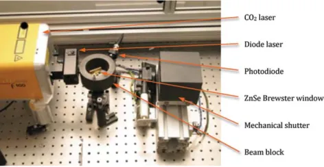
The CO2 laser can be power stabilized using a
proportional-integral-derivative (PID) control system. A small fraction of the laser beam is picked off using a ZnSe Brewster window mounted near the Brewster angle, as shown in Fig.3. The power of this pick-off beam is measured us-ing a mercury–cadmium–telluride photodiode, with the sig-nal being fed back to the computer. A PID system running on the control computer is used to generate an error signal that is fed back to the laser. In operation when using the power stabilization system, the laser is typically allowed to stabilize for some time by using a mechanical shutter before the fiber pulling routine is started. Using this system the laser power can be stabilized to better than 1% over timescales of tens of minutes. In practice the laser is stable enough after warming
FIG. 3. (Color) Power stabilization system. A small percentage of the laser power is picked off using a ZnSe Brewster window and measured using a photodiode. A graphite beam block is used to remove unwanted reflections.
up to be run without using the power stabilization when pro-ducing fibers where the dimensional tolerances are not critical and when performing welds.
A. Producing cylindrical cross-section fibers
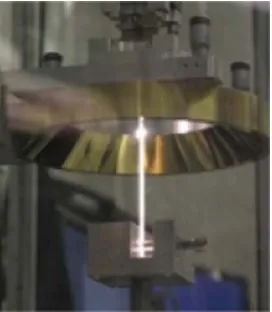
Figure4shows the design of the cylindrical fiber pulling machine inSOLIDWORKS. Fibers are pulled from fused silica rod by heating and using a feed–pull method to produce the fiber. The rod must be heated in a uniform way in order to produce a cylindrical cross-section fiber. Figure5shows the optical layout that allows a section of the rod to be heated from all sides giving a perfectly symmetric uniform heating about the central vertical axis of the stock. The beam is fed onto an upper fixed mirror, angled at 45◦ to vertical, which reflects it down onto another 45◦ mirror that is spinning at approximately 20 rps. This spinning mirror scans the beam around the inside surface of a conical mirror, from where it is reflected upward, forming a cylinder of light. This cylinder hits another conical mirror that reflects the beam inward and onto the stock material. In this way, the stock is heated from all sides, and a uniform heat delivery is achieved. With the current 130 W CO2laser, rods with diameters of up to 5 mm
can be used.
The lower part of the cylindrical fused silica rod is fixed in a clamp that is fixed to the base of the machine. The upper end of the rod is fixed in a clamp that it attached to the upper movable arm. As the fiber is heated, the stock material is fed into beam path by moving the lower arm holding the upper conical mirror down over the stock. At the same time the fiber is drawn out of the melt by moving the upper arm upward. The volume of silica fed into the melt matches that pulled from the melt, and thus the diameter of fiber produced can be calculated simply from the starting rod diameter and the speeds of the two carriages. Figure6shows a photograph of a cylindrical fiber being pulled from a 3 mm silica rod.
B. Producing rectangular cross-section fibers
[image:4.612.320.556.53.175.2]FIG. 4. (Color)SOLIDWORKSrendering of the fiber pulling machine in cylindrical fiber configuration. The functions of all parts are described in the text.
which were pulled from 10:1 aspect ratio fused silica slides 110 mm long by 5 mm×0.5 mm. Having chosen the correct aspect ratio, the dimensions of the stock material were picked to give a suitable shaped end to weld onto an ear on the side of a test mass.
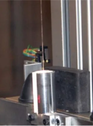
To heat the rectangular stock, the conical mirror beam delivery system is replaced by a single mirror galvanometer mounted on a rigid post in front of the machine. This machine setup is shown in Fig.7. The galvanometer is driven with a signal to dither the beam across the piece of stock to achieve an even heating. Due to the extra heat loss at the edges of the stock, it is necessary for the beam to spend more time over these regions. A cylindrical polished steel heat shield, as shown in Fig.8, was designed to sit around the stock mate-rial during heating to reflect heat back at the edges, reducing
FIG. 5. (Color) Rendered drawing of the laser beam delivery for cylindrical fiber production.
the heat loss. The galvanometer is driven using an arbitrary waveform generator with a trapezoidal waveform. The slop-ing edge of the trapezoid moves the heat uniformly across the slide surface, while the flat top and bottom of the trapezoid can be lengthened or shortened to alter the relative heating of the edges of the slide. The galvanometer is servo controlled and uses a low mass mirror allowing it to be used up to sev-eral kilohertz. While the actual rate of the galvanometer is much lower than this, it is necessary to have good high fre-quency response to generate both square wave and triangle shapes which have higher order mode content.
The fused silica stock is fixed into clamps that are at-tached to the upper and lower carriages. With the height of the laser beam now fixed relative to the optical table, the sil-ica stock is fed into the beam by moving the lower carriage upward. The fiber is simultaneously pulled by moving the up-per carriage at a higher speed than the lower carriage. Again it
[image:5.612.140.471.52.286.2] [image:5.612.53.291.530.725.2] [image:5.612.371.507.568.724.2]FIG. 7. (Color) Rectangular cross-section fiber pulling machine. Ribbons are pulled from rectangular silica slides. The laser is dithered across the surface using a mirror galvanometer seen here at the front right hand side.
is simple to calculate the ratio of reduction in cross-sectional area based on the speed of the two carriages.
The heating control was found to be more critical when pulling ribbons than for cylindrical fibers. When the silica be-gins to melt and becomes less viscous, the surface tension acts to pull the fiber toward a cylindrical geometry. If the sil-ica is heated hot enough it is in fact possible to pull a cylin-drical cross-section fiber from the rectangular stock. By con-trolling the laser power it is possible to control the shape of the cross section such that a ribbon with 10:1 aspect ratio is produced.
In practice this relationship between heating and cross-sectional shape puts a constraint on the way in which rib-bon fibers can be manufactured that is not seen with cylin-drical fibers, limiting the temperature to which the silica can
FIG. 8. (Color) Photograph of a ribbon being pulled. The heating zone and stock material are enclosed in a steel heat shield to minimize heat loss from the edges.
be raised. This temperature limit in turn was seen to limit the strength of the fibers. It is thought that surface cracks in the stock material were not easily removed by pulling at lower temperatures. A further stage of laser polishing was in-troduced in order to meet the strength requirements for Ad-vanced LIGO.
By varying the speed while pulling the ribbon, it was pos-sible to produce tapered ribbons in a similar manner to the tapered cylindrical fibers.
III. FIBER PERFORMANCE
The requirements for fiber performance in the Advanced LIGO monolithic suspensions are set out in the design re-quirements document for cavity optics49 and the monolithic
stage conceptual design document.50
The thermal noise requirement for Advanced LIGO sus-pension fibers is that longitudinal displacement noise must be 1×10⁻¹⁹m/√Hz or less at 10 Hz. Assuming cancella-tion of the thermoelastic losses, this requirement can be ex-pressed as a limit on the surface loss times the thickness of lossy layer,hφsurface=1.9×10⁻¹¹. This is a convenient
pa-rameter to choose since it is independent of fiber diameter. A recent publication51presenting measurements of the mechan-ical dissipation in cylindrmechan-ical fibers produced using this ma-chine shows an average value ofhφsurface=5×10⁻¹²m. This
value is comparable to values for gas pulled fibers29 of
ap-proximatelyhφsurface=5.9×10⁻¹²m and meets the require-ment for Advanced LIGO.
Fibers with dimensions suitable for Advanced LIGO were pulled using the machine based at MIT and were de-structively strength tested. The fibers were produced using a polishing technique that will be described in a future publica-tion, and had their diameters measured along their length to calculate the stress. The average breaking stress of the fibers was 4.4 GPa. Even the weakest fiber measured would provide a safety margin of three times the working load for either the Virgo or LIGO upgrades.
The requirement for vertical stiffness of 2.8% sets a tol-erance on fiber dimensions. In practice this is most easily checked by measurement of the vertical bounce mode of the fiber when loaded. Measurement of the bounce mode of sets of fibers, each loaded with a 1 kg mass, gave a spread of bounce frequencies at the 0.8% level for fibers produced in the same batch, well within the requirements for Advanced LIGO. Assuming that the weight of the test mass is evenly distributed on all four fibers, the length of the fibers needs to be within±0.6 mm of each other to keep the violin modes grouped to within 1 Hz. With fiber lengths varying at the level of 0.3 mm, this requirement should easily be met.
The final requirement is on the position of the fiber flex-ure point. The tolerance required here is approximately±0.1 mm in horizontal and 1 mm in vertical. The horizontal re-quirement comes from the static pitch which can be adjusted over a range of 20 Mrad, with the test mass having a pitch compliance of 0.154 rad/N m calculated using a model of the quad suspension.37 Since this adjustment range must also
[image:6.612.54.295.51.240.2] [image:6.612.98.252.506.715.2]of this adjustment range, corresponding to 0.1 mm in flexure position. The 1 mm tolerance on the vertical position of the flexure point comes from a requirement that the frequency of the first pitch mode of the suspension be above the first longi-tudinal mode. These tolerances are met by using jigs to hold and move the fibers precisely during welding.
IV. WELDING SYSTEMS
To reduce friction in the joints of the mirror suspensions, fused silica fibers are typically welded to fused silica attach-ment blocks that are hydroxide-catalysis bonded to the sides of the optic.17–19 The suspensions for GEO600 were welded
by hand using a hydrogen–oxygen torch. Again there are ad-vantages to moving to using a laser which offers a more re-producible process.
Two methods of CO2laser welding were developed. The
first was developed to weld smaller parts that could be placed close to the machine, preferably on the optical bench. The cylindrical fiber pulling machine has a modular design that allows it to be switched to become a welding system by re-placement of one section of the machine.
The second scheme was developed to give localized beam delivery when welding larger suspensions that are not on the optical bench. This allows the beam to be delivered to specific weld locations on the Advanced LIGO suspension structure with the beam being enclosed when it is not on the bench.
Both systems use a 130 W CO2laser which sets a
practi-cal limit to the size of piece that can be welded. It was found that welds could easily penetrate to a depth of around 3 mm using this laser.
A. Welding to structures on the optical bench
The design of the fiber pulling machine incorporates the ability for it to be used as a robotic welding system. The sys-tem was designed to perform welds to structures located close to or on the optics bench. It is capable of delivering the beam over an area of approximately 1 m2 in order to reach all the
weld locations, but also gives fine control at the submillimeter level to perform fine welds.
The upper conical mirror of the fiber pulling machine, as shown in Fig.4, is replaced by a double galvanometer head giving a fine x–y delivery of the beam using a joystick control. The galvanometers are mounted on the horizontal ballscrew which in turn is mounted on the vertical ballscrew unit. These give the galvanometer head a wide range motion of 1 m hor-izontally and 1.2 m vertically, and again are joystick con-trolled. The laser is then rerouted using a flipper mirror to travel vertically up the side of the machine and along the hori-zontal arm to the galvanometers, from where it can be directed to the weld location. Each of the three fiber pulling machines is equipped with this system. For practical reasons the hori-zontal ballscrew unit can be removed from the machine when not in use, for example, when using the alternative welding system to build suspensions.
FIG. 9. (Color) The welding system consists of a CO2 laser delivered through an articulated arm, ZnSe output telescope, and a pair of mirror gal-vanometers.
B. Welding to remote structures
When welding to structures that cannot easily be located on the optical bench, it is safer and easier to use an enclosed beam that can be delivered to different locations. A remote welding system was devised based on a commercially avail-able Zeiss articulated arm, as shown in Fig.9. This arm con-tains gold coated mirrors mounted at 45◦in each joint. At each of these joints, the arm is constrained to rotate only about the optical axis along which the laser beam is traveling allow-ing the beam to stay centered on each mirror along the arm’s length once it has been aligned.
At the end of the arm, ZnSe lenses are used to focus the beam. The lenses form a compact telescope 10 cm in length. The separation of the lenses can be altered, allowing the power density and diameter to be varied at the welding point. A calibration chart was produced for the telescope, giving the beam diameter at the weld location as a function of lens separation.
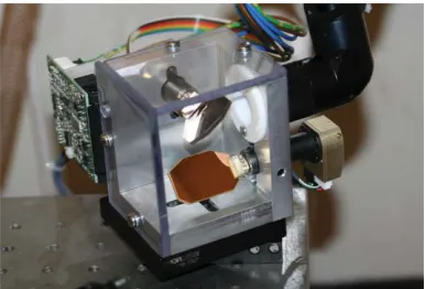
From the telescope, the beam is reflected from two mir-ror galvanometers, as shown in Fig.10, that are mounted at right angles to each other on the end of the arm. The mir-ror galvanometers are servo controlled, with the positional
[image:7.612.348.529.51.240.2] [image:7.612.342.535.592.723.2]information coming from a customLABVIEWscript. The pro-gram is preset to limit the movement of the galvanometers to keep the beam within the area of the weld so as to increase safety. The beam can then be moved over the weld using the computer cursor keys. The beam can also be dithered over the weld area by scanning the beam using a continuous wave input. Using the articulated arm, the galvanometers can be moved to predetermined locations on the suspension structure close to the ends of the fiber before fixing the position of the end of the arm, and performing the weld.
V. CONCLUSIONS
A CO2 laser-based fused silica fiber pulling machine
was developed that is capable of meeting requirements for strength, thermal noise performance, and dimensional toler-ance for the next generation of gravitational wave detector mirror suspensions. The ability to produce circular and rect-angular cross-section fibers was developed, as well as tapering along the length of the fiber. Two laser welding methods were investigated, allowing for smaller parts to be welded on the optical bench, and large suspensions such as those planned for Advanced LIGO, to be welded by delivering the beam to the weld locations using an articulated arm. The MIT-based machine has been used to build the monolithic suspension for the LASTI noise prototype and will soon be relocated to the Hanford LIGO site where it will be used to produce suspen-sion fibers for Advanced LIGO. The separate welding system for use on remote structures will be used for welding the sus-pensions close to the vacuum tanks at the Hanford and Liv-ingston LIGO sites. The machine at the Virgo site has been used to build a prototype suspension for the Virgo upgrade, and is now being used to produce the new suspensions for the interferometer at the site.
ACKNOWLEDGMENTS
The authors would like to thank Colin Craig and Stephen Craig for their work toward the construction of the laser fiber pulling machine. We would like to thank our colleagues in the GEO600 project, the Scottish Universities Physics Alliance (SUPA), and the LIGO Scientific Collaboration for their in-terest in this work. We also wish to thank the ILIAS Strega project and Leverhulme Trust for support. We are grateful for the financial support provided by the STFC and the Univer-sity of Glasgow in the UK and the NSF in the USA. The LIGO Observatories were constructed by the California In-stitute of Technology and Massachusetts InIn-stitute of Technol-ogy with funding from the NSF under cooperative agreement PHY-9210038. The LIGO Laboratory operates under cooper-ative agreement PHY-0107417.
1H. B. Callen and T. A. Welton,Phys. Rev.83, 34 (1951). 2H. B. Callen and R. F. Greene,Phys. Rev.86, 702 (1952). 3P. R. Saulson,Phys. Rev. D42, 2437 (1990).
4Y. Levin,Phys. Rev. D57, 659 (1998).
5S. Rowan, J. Hough, and D. Crooks,Phys. Lett. A347, 25 (2005). 6V. Braginsky, V. Mitrofanov, and O. Okhrimenko,Phys. Lett. A175, 82
(1993).
7V. B. Braginsky, V. P. Mitrofanov, and K. V. Tokmakov,Phys. Lett. A186, 18 (1994).
8S. Rowan, S. M. Twyford, R. Hutchins, J. Kovalik, J. E. Logan, A. C.
McLaren, N. A. Robertson, and J. Hough,Phys. Lett. A233, 303 (1997). 9A. Ageev, B. C. Palmer, A. D. Felice, S. D. Penn, and P. R. Saulson,Class.
Quantum Grav.21, 3887 (2004).
10K. Numata, K. Yamamoto, H. Ishimoto, S. Otsuka, K. Kawabe, M. Ando,
and K. Tsubono,Phys. Lett. A327, 263 (2004).
11S. D. Penn, A. Ageev, D. Busby, G. M. Harry, A. M. Gretarsson, K.
Nu-mata, and P. Willems,Phys. Lett. A352, 3 (2006).
12V. B. Braginsky, V. P. Mitrofanov, and V. I. Panov, inSystems with Small
Dissipation, edited by K. S. Thorne (University of Chicago Press, Chicago, 1986).
13Y. L. Huang and P. R. Saulson,Rev. Sci. Instrum.69, 544 (1998). 14G. Cagnoli, L. Gammaitoni, J. Kovalik, F. Marchesoni, and M. Punturo,
Phys. Lett. A255, 230 (1999).
15G. Cagnoli, L. Gammaitoni, J. Kovalik, F. Marchesoni, and M. Punturo,
Phys. Lett. A213, 245 (1996).
16B. Willke, P. Aufmuth, C. Aulbert, S. Babak, R. Balasubramanian,
B. W. Barr, S. Berukoff, S. Bose, G. Cagnoli, M. M. Casey, D. Churches, D. Clubley, C. N. Colacino, D. R. M. Crooks, C. Cutler, K. Danzmann, R. Davies, R. Dupuis, E. Elliffe, C. Fallnich, A. Freise, S. Gossler, A. Grant, H. Grote, G. Heinzel, A. Heptonstall, M. Heurs, M. Hewitson, J. Hough, O. Jennrich, K. Kawabe, K. Kotter, V. Leonhardt, H. Luck, M. Malec, P. W. McNamara, S. A. McIntosh, K. Mossavi, S. Mohanty, S. Mukherjee, S. Nagano, G. P. Newton, B. J. Owen, D. Palmer, M. A. Papa, M. V. Plissi, V. Quetschke, D. I. Robertson, N. A. Robertson, S. Rowan, A. Rudiger, B. S. Sathyaprakash, R. Schilling, B. F. Schutz, R. Senior, A. M. Sintes, K. D. Skeldon, P. Sneddon, F. Stief, K. A. Strain, I. Taylor, C. I. Torrie, A. Vecchio, H. Ward, U. Weiland, H. Welling, P. Williams, W. Winkler, G. Woan, and I. Zawischa,Class. Quantum Grav.19, 1377 (2002). 17D. Gwo, U.S. patent 6,548,176 B1 (2003).
18S. Rowan, S. M. Twyford, J. Hough, D. H. Gwo, and R. Route,Phys. Lett.
A246, 471 (1998).
19P. H. Sneddon, S. Bull, G. Cagnoli, D. R. M. Crooks, E. J. Elliffe, J. E.
Faller, M. M. Fejer, J. Hough, and S. Rowan,Class. Quantum Grav.20, 5025 (2003).
20S. Goßler, G. Cagnoli, D. R. M. Crooks, H. Lück, S. Rowan, J. R. Smith,
K. A. Strain, J. Hough, and K. Danzmann,Class. Quantum Grav.21, S923 (2004).
21B. Sorazu, K. A. Strain, I. S. Heng, and R. Kumar,Class. Quantum Grav.
27, 155017 (2010).
22N. A. Robertson, G. Cagnoli, D. R. M. Crooks, E. Elliffe, J. E. Faller,
P. Fritschel, S. Goßler, A. Grant, A. Heptonstall, J. Hough, H. Lück, R. Mittleman, M. Perreur-Lloyd, M. V. Plissi, S. Rowan, D. H. Shoemaker, P. H. Sneddon, K. A. Strain, C. I. Torrie, H. Ward, and P. Willems,Class. Quantum Grav.19, 4043 (2002).
23P. Amico, L. Bosi, L. Carbone, L. Gammaitoni, M. Punturo, F. Travasso,
and H. Vocca,Class. Quantum Grav.19, 1669 (2002).
24SOLIDWORKS3D CAD Software, Dassault Systemes SolidWorks Corp.,
Concord, Massachusetts, USA.
25A. S. Nowick and B. S. Berry,Anelastic Relaxation in Crystalline Solids
(Academic, New York, 1972). 26C. Zener,Phys. Rev.53, 90 (1938).
27G. Cagnoli and P. A. Willems,Phys. Rev. B65, 174111 (2002).
28J. Wiedersich, S. V. Adichtchev, and E. Rössler,Phys. Rev. Lett.84, 2718 (2000).
29A. M. Gretarsson and G. M. Harry, Rev. Sci. Instrum. 70, 4081 (1999).
30P. Willems, V. Sannibale, J. Weel, and V. Mitrofanov,Phys. Lett. A297, 37 (2002).
31A. Heptonstall, G. Cagnoli, J. Hough, and S. Rowan,Phys. Lett. A354, 353 (2006).
32N. A. Robertson, M. Barton, and J. Greenhalgh, LIGO Document No.
T040143, 2004, available athttps://dcc.ligo.org/.
33G. Cagnoli and C. A. Cantley, LIGO Document No. T050212, 2005,
avail-able athttps://dcc.ligo.org/.
34G. Cagnoli, J. Hough, D. DeBra, M. M. Fejer, E. Gustafson, S. Rowan, and
V. Mitrofanov,Phys. Lett. A272, 39 (2000). 35P. Willems,Phys. Lett. A300, 162 (2002).
36M. Barton, A. Heptonstall, C. Craig, A. Cumming, L. Cunningham,
37M. Barton, LIGO Document No. T1000263, 2010, available at
https://dcc.ligo.org/.
38J. D. Strong,Procedures in Experimental Physics(Prentice-Hall,
Engle-wood Cliffs, NJ, 1938).
39T. T. O’Donnell,Drawing and Working Quartz Fibers(National Academy
of Sciences—National Research Council, Washington, 1958).
40S. Rowan, R. Hutchins, A. McLaren, N. A. Robertson, S. M. Twyford, and
J. Hough,Phys. Lett. A227, 153 (1997).
41A. Cavalleri, G. Ciani, R. Dolesi, A. Heptonstall, M. Hueller, D. Nicolodi,
S. Rowan, D. Tombolato, S. Vitale, P. J. Wass, and W. J. Weber,Class. Quantum Grav.26, 094017 (2009).
42A. Cavalleri, G. Ciani, R. Dolesi, A. Heptonstall, M. Hueller, D. Nicolodi,
S. Rowan, D. Tombolato, S. Vitale, P. J. Wass, and W. J. Weber,Phys. Rev. Lett.103, 140601 (2009).
43V. P. Mitrofanov, O. I. Ponomareva, and A. A. Khorev, Zh. Tekh. Fiz.55, 765 (1985).
44V. K. Sysoev, B. P. Papchenko, and S. Y. Rusanov,Glass Ceram.61, 106 (2004).
45G. Harry, T. Corbitt, M. Freytsis, D. Ottaway, N. Mavalvala, and S. Penn,
Rev. Sci. Instrum.77, 023906 (2006).
46C. Kurkjian, J. Krause, and M. Matthewson,J. Lightwave Technol.7, 1360 (1989).
47P. Willems and M. Thattai,Phys. Lett. A253, 16 (1999).
48A. Cumming, A. Heptonstall, R. Kumar, W. Cunningham, C. Torrie,
M. Barton, K. A. Strain, J. Hough, and S. Rowan,Class. Quantum Grav.
26, 215012 (2009).
49M. Barton, N. Robertson, P. Fritschel, D. Shoemaker, and P. Willems, LIGO
Document No. T010007, 2008, available athttps://dcc.ligo.org/. 50C. A. Cantley, H. Armandula, M. Barton, G. Cagnoli, A. Cumming,
D. Crooks, E. Elliffe, R. J.S. Greenhalgh, T. Hayler, A. Heptonstall, J. Hough, R. Jones, J. O’Dell, I. Martin, M. Perreur-Lloyd1, N. A. Robert-son, J. Romie, S. Rowan, K. A. Strain, C. Torrie, and I. Wilmut, LIGO Document No. T050215, 2005, available athttps://dcc.ligo.org/. 51A. Heptonstall, M. Barton, C. Cantley, A. Cumming, G. Cagnoli, J. Hough,