Random Network Coding for Multimedia Delivery
Services in LTE/LTE-Advanced
Dejan Vukobratovi´c, Chadi Khirallah, Vladimir Stankovi´c, John Thompson
Abstract—Random Network Coding (RNC) has recently been investigated as a promising solution for reliable multimedia delivery over wireless networks. RNC possess the potential for flexible and adaptive matching of packet-level error resilience to both video content importance and variable wireless channel conditions. As the demand for massive multimedia delivery over fourth generation wireless cellular standards such as Long-Term Evolution (LTE)/LTE-Advanced (LTE-A) increases, novel video-aware transmission techniques are needed. In this paper, we investigate RNC as one such promising technique, building upon our recent work on RNC integration within the LTE/LTE-A Radio Access Network at the Multiple Access Control (MAC) layer (RNC). The paper argues that the proposed MAC-RNC solution provides fundamentally new set of opportunities for dynamic collaborative transmission, content awareness, resource allocation and unequal error protection (UEP) necessary for efficient wireless multimedia delivery in LTE/LTE-A.
Index Terms—LTE/LTE-A, Random Network Coding, Wireless Video Delivery
I. INTRODUCTION
Recent technological advances both at the user and the network side are bringing advanced multimedia delivery ser-vices over mobile cellular networks closer to reality. Indeed, today’s smartphones are powerful handheld computers with large screen sizes/resolutions while user data rates offered by fourth generation cellular interfaces such as 3GPP Long-Term Evolution (LTE)/LTE-Advanced (LTE-A) satisfy high-quality multimedia streaming demands. In recent years, several mobile multimedia delivery services have been standardized, evolved and commercially used; the most notable examples include the 3GPP Packet-Switched Service (PSS) [1], the 3GPP Multimedia Broadcast/Multicast Service (MBMS) [2] and adaptive HTTP streaming (AHS) [3][4]. However, apart from these upper layer efforts, LTE/LTE-A radio access net-work (RAN) protocols remains largely oblivious to multimedia traffic, with rare exceptions in the domain of priority-based scheduling and resource allocation [5]. This is in contrast with predictions that multimedia traffic will dominate future mobile cellular networks [6]. Thus, despite the fact that the LTE/LTE-A physical layer represents the state-of-the-art in
The work reported in this paper was part funded by the EPSRC Sensor Signal Processing Platform Grant EP/J015180/1. Dejan Vukobratovi´c was supported by a Marie Curie European Reintegration Grant FP7-PEOPLE-ERG-2010 MMCODESTREAM within the 7th EU Framework Programme.
Dejan Vukobratovi´c is with the Dept. of Power, Electronics and Communi-cation Engineering, University of Novi Sad, Novi Sad, Serbia. Chadi Khirallah and John Thompson are with the School of Engineering and Electronics, University of Edinburgh, Edinburgh, UK. Vladimir Stankovi´c is with the Dept. of Electronic and Electrical Engineering, University of Strathclyde, Glas-gow, UK. Email: [email protected], {c.khirallah,john.thompson}@ed.ac.uk, [email protected].
communications technology, novel solutions for LTE/LTE-A adaptation to multimedia services are needed [7].
Random Network Coding (RNC) has recently been de-ployed on the latest generation smartphones as a promising application layer solution for reliable multimedia delivery over wireless links [8][9]. RNC is based on random linear coding [10] and may be understood and applied both as a rateless coding solution for unicasting/multicasting of short messages (short in terms of the number of message pack-ets) [11], and as a network coding solution for throughput enhancement in multi-hop/cooperative wireless environments [12]. Unequal error protection (UEP) RNC extensions [13] in combination with sparse RNC [14] represent promising approach for a low-complexity, adaptive and content-aware packet-level error-resilience solution. Given the unique flex-ibility of RNC to efficiently bridge the upper-layer media compression/packetization and the lower-layer wireless packet transmission, in this letter, we consider RNC as a power-ful cross-layer solution for reliable multimedia delivery over LTE/LTE-A. We provide detailed performance analysis of 3GPP LTE/LTE-A multimedia delivery services, building upon our work on the MAC-RNC protocol proposed as a replace-ment for the MAC layer Hybrid Automatic Repeat reQuest (MAC-HARQ) protocol [15]. The MAC-RNC protocol pro-vides a simple and efficient RAN-wide rateless/network coding MAC sublayer designed to improve the delivery of upper-layer packets across a single or multi-hop RAN topologies such as LTE-A Heterogeneous Networks (HetNets) [16]. It is designed to increase throughput, simplify system design, support dynamic (opportunistic) collaborative data delivery or exchange in HetNets and enable multimedia content awareness within lower-layer LTE RAN protocols.
II. MAC-HARQVSMAC-RNC SOLUTIONS FOR
LTE/LTE-A
In this section, we shortly review LTE RAN protocol stack, both the version proposed in 3GPP standard [17]-[19], and the modification based on MAC-RNC proposed in [15].
A. 3GPP LTE RAN Protocol Stack: A Review
...
...
PHY TB MAC PDU
...
...
...
TB PDU
RLC PDU
MAC PDU
PHY TB PDU
1
1 8
TB
10
TTI TTI
PDCP PDU
RLC Segmentation ARQ Process
H-ARQ Process
(8 MAC PDUs inParallel)
RLC Layer IP/PDCP Layer
MAC Layer
PHY Layer RLC PDU
...
...
...
...
RLC SDU
1 Radio Frame 10ms
(a) MAC-HARQ solution.
00000000000000000000000000000000000000000000000000000000000000000000000000000000000000000000000000000000000000000000000000000000000000000000000000000000000000000000000000000000000000000000000000000000000000000000000000000000000000000000000000000000000000000000000000000000000000000000000000000000000000000000000000000000000000000000000000000000 00000000000000000000000000000000000000000000000000000000000000000000000000000000000000000000000000000000000000000000000000000000000000000000000000000000000000000000000000000000000000000000000000000000000000000000000000000000000000000000000000000000000000000000000000000000000000000000000000000000000000000000000000000000000000000000000000000000 00000000000000000000000000000000000000000000000000000000000000000000000000000000000000000000000000000000000000000000000000000000000000000000000000000000000000000000000000000000000000000000000000000000000000000000000000000000000000000000000000000000000000000000000000000000000000000000000000000000000000000000000000000000000000000000000000000000 00000000000000000000000000000000000000000000000000000000000000000000000000000000000000000000000000000000000000000000000000000000000000000000000000000000000000000000000000000000000000000000000000000000000000000000000000000000000000000000000000000000000000000000000000000000000000000000000000000000000000000000000000000000000000000000000000000000 00000000000000000000000000000000000000000000000000000000000000000000000000000000000000000000000000000000000000000000000000000000000000000000000000000000000000000000000000000000000000000000000000000000000000000000000000000000000000000000000000000000000000000000000000000000000000000000000000000000000000000000000000000000000000000000000000000000 00000000000000000000000000000000000000000000000000000000000000000000000000000000000000000000000000000000000000000000000000000000000000000000000000000000000000000000000000000000000000000000000000000000000000000000000000000000000000000000000000000000000000000000000000000000000000000000000000000000000000000000000000000000000000000000000000000000 00000000000000000000000000000000000000000000000000000000000000000000000000000000000000000000000000000000000000000000000000000000000000000000000000000000000000000000000000000000000000000000000000000000000000000000000000000000000000000000000000000000000000000000000000000000000000000000000000000000000000000000000000000000000000000000000000000000 00000000000000000000000000000000000000000000000000000000000000000000000000000000000000000000000000000000000000000000000000000000000000000000000000000000000000000000000000000000000000000000000000000000000000000000000000000000000000000000000000000000000000000000000000000000000000000000000000000000000000000000000000000000000000000000000000000000 00000000000000000000000000000000000000000000000000000000000000000000000000000000000000000000000000000000000000000000000000000000000000000000000000000000000000000000000000000000000000000000000000000000000000000000000000000000000000000000000000000000000000000000000000000000000000000000000000000000000000000000000000000000000000000000000000000000 00000000000000000000000000000000000000000000000000000000000000000000000000000000000000000000000000000000000000000000000000000000000000000000000000000000000000000000000000000000000000000000000000000000000000000000000000000000000000000000000000000000000000000000000000000000000000000000000000000000000000000000000000000000000000000000000000000000 00000000000000000000000000000000000000000000000000000000000000000000000000000000000000000000000000000000000000000000000000000000000000000000000000000000000000000000000000000000000000000000000000000000000000000000000000000000000000000000000000000000000000000000000000000000000000000000000000000000000000000000000000000000000000000000000000000000 00000000000000000000000000000000000000000000000000000000000000000000000000000000000000000000000000000000000000000000000000000000000000000000000000000000000000000000000000000000000000000000000000000000000000000000000000000000000000000000000000000000000000000000000000000000000000000000000000000000000000000000000000000000000000000000000000000000 00000000000000000000000000000000000000000000000000000000000000000000000000000000000000000000000000000000000000000000000000000000000000000000000000000000000000000000000000000000000000000000000000000000000000000000000000000000000000000000000000000000000000000000000000000000000000000000000000000000000000000000000000000000000000000000000000000000 00000000000000000000000000000000000000000000000000000000000000000000000000000000000000000000000000000000000000000000000000000000000000000000000000000000000000000000000000000000000000000000000000000000000000000000000000000000000000000000000000000000000000000000000000000000000000000000000000000000000000000000000000000000000000000000000000000000 00000000000000000000000000000000000000000000000000000000000000000000000000000000000000000000000000000000000000000000000000000000000000000000000000000000000000000000000000000000000000000000000000000000000000000000000000000000000000000000000000000000000000000000000000000000000000000000000000000000000000000000000000000000000000000000000000000000 00000000000000000000000000000000000000000000000000000000000000000000000000000000000000000000000000000000000000000000000000000000000000000000000000000000000000000000000000000000000000000000000000000000000000000000000000000000000000000000000000000000000000000000000000000000000000000000000000000000000000000000000000000000000000000000000000000000 00000000000000000000000000000000000000000000000000000000000000000000000000000000000000000000000000000000000000000000000000000000000000000000000000000000000000000000000000000000000000000000000000000000000000000000000000000000000000000000000000000000000000000000000000000000000000000000000000000000000000000000000000000000000000000000000000000000 00000000000000000000000000000000000000000000000000000000000000000000000000000000000000000000000000000000000000000000000000000000000000000000000000000000000000000000000000000000000000000000000000000000000000000000000000000000000000000000000000000000000000000000000000000000000000000000000000000000000000000000000000000000000000000000000000000000 00000000000000000000000000000000000000000000000000000000000000000000000000000000000000000000000000000000000000000000000000000000000000000000000000000000000000000000000000000000000000000000000000000000000000000000000000000000000000000000000000000000000000000000000000000000000000000000000000000000000000000000000000000000000000000000000000000000 00000000000000000000000000000000000000000000000000000000000000000000000000000000000000000000000000000000000000000000000000000000000000000000000000000000000000000000000000000000000000000000000000000000000000000000000000000000000000000000000000000000000000000000000000000000000000000000000000000000000000000000000000000000000000000000000000000000
Z>^h
...
Z>>ĂLJĞƌ
dϭ dϮ dϭϬ
ϭZĂĚŝŽ&ƌĂŵĞ;ϭϬŵƐͿ Z>Wh
/WͬWW>ĂLJĞƌ
1
x x2 xK
DͲZE ƐƵďͲ>ĂLJĞƌ
1
g
2
g
K
g
i
c ci+1 ci+2 ci+3 ci+4
D>ĂLJĞƌ
DWhƐ
W,z>ĂLJĞƌ
dƌĂŶƐƉŽƌƚ ůŽĐŬƐ
... ...
...
... Z>^h WWWh WWWh
ŽŶƚĞŶƚͲǁĂƌĞ
(b) MAC-RNC solution.
Fig. 1. eNB DL IP packet flow from IP to PHY layer using MAC-HARQ and MAC-RNC solution.
TABLE I
CQIVALUES AND THE CORRESPONDINGPHYPARAMETERS
(SINGLE-INPUTSINGLE-OUTPUT(SISO) CONFIGURATION).
CQI modulation code bits per SINR TBS index rate symbol (dB) (bits)
0−3 No Tx - - <−1.25 0
4 QPSK 0.3 0.6016 −0.94 384
5 QPSK 0.44 0.8770 1.09 576
6 QPSK 0.59 1.1758 2.97 768
7 16QAM 0.37 1.4766 5.31 960 8 16QAM 0.48 1.9141 6.72 1152 9 16QAM 0.6 2.4063 8.75 1536 10 64QAM 0.45 2.7305 10.47 1920 11 64QAM 0.55 3.3223 12.34 2304 12 64QAM 0.65 3.9023 14.37 2688 13 64QAM 0.75 4.5234 15.94 3072 14 64QAM 0.85 5.1152 17.81 3456 15 64QAM 0.93 5.5547 20.31 3840
(PDCP). After header compression and ciphering, PDCP en-capsulated IP packets (IP/PDCP) are delivered to the Radio Link Control (RLC) layer. The RLC layer performs segmen-tation/concatenation of IP/PDCP packets into RLC packets to fit the MAC frame size requirements, which are in turn selected to fit the physical layer (PHY) transport block (TB) size. Thus each MAC frame is allocated a single PHY TB for transmission over the eNB/UE interface. For unicast services, reliable MAC frame delivery over eNB/UE link is supported by the MAC-HARQ mechanism. If HARQ retransmissions fail, and if the RLC-layer Acknowledged Mode (AM) is used, an additional RLC-level ARQ mechanism is used to guarantee reliable RLC packet delivery [18].
The PHY TB is a PHY layer packet mapped to a unit of PHY time-frequency resources on the wireless link called
resource block pair (RBP). One PHY RBP is equal to 1 ms
of time duration: a time slot called transmission time interval
(TTI), and 12 OFDM carriers (180 kHz) of bandwidth. The
PHY TB size (TBS) in every TTI depends on: i) the adaptive modulation/coding scheme selected by the MAC scheduler based on the channel quality indicator (CQI) reported by the
UE, and ii) the numberNRBP of PHY RBPs allocated to the
UE (see Table I, TBS column, for the caseNRBP = 6).
B. MAC Layer Random Network Coding (MAC-RNC)
The MAC-RNC solution in Fig. 1(b) is proposed as a replacement for the MAC-HARQ protocol [15]. The two solutions differ starting from the RLC layer and represent two alternatives for reliable delivery of RLC encapsulated IP/PDCP packet over the eNB/UE interface.
The standardized solution delivers PDCP/IP packet through parallel, independent and time-interleaved delivery of its dis-joint segments (MAC frames), supported by the MAC-HARQ protocol for reliable delivery (see Fig. 1(a)). The PDCP/IP packet is received once all of its RLC/MAC encapsulated segments are received by the UE [18].
In contrast, the proposed MAC-RNC scheme does not seg-ment the PDCP/IP packet. Instead, the RLC layer encapsulates the PDCP/IP packet directly into the RLC packet. This pre-serves the integrity of IP packets carrying video content data units (e.g., H.264/AVC Network Adaptation Layer - NAL units [20]). In case the larger RLC packets are desirable by the MAC layer, the RLC layer concatenates multiple PDCP/IP packets into a single RLC packet (Fig. 1(b)). At the MAC layer, RLC message is processed by the MAC-RNC sublayer: it is divided
into K equal-length source symbols from which a stream of
RNC-encoded symbols is produced. We assume systematic RNC approach, where the source symbols are transmitted first, followed by a rateless stream of encoded symbols representing random linear combination over GF(256) [15]. An appropriate number of equal-length encoded symbols are grouped into a MAC frame to fit the upcoming PHY TBS reported by the MAC scheduler. The MAC frame is encapsulated into the PHY TB and transmitted without HARQ retransmissions. From each correctly received PHY TB at the UE, the set of encoded packets is extracted and delivered to the progressive GE decoder at the MAC-RNC decoding sublayer. We assume RNC coding coefficients are recovered by using common seed of the random number generator (see [15] for details). As soon
asK linearly independent encoded packets are received from
the stream of MAC frames, the UE MAC entity feeds back a single ACK message finalizing the RLC packet delivery.
The key MAC-RNC design issue is to select appropriate
symbol size so that: i) the source message length K ∼100
tightly fit the variable size PHY TBS. The PHY TBS grows proportionally to the PHY RBP allocation and the CQI value
reported by the UE. In [15], a flexible symbol size of L =
4·NRBP bytes is proposed that results in encapsulation of
2 to 20encoded symbols per MAC frame (depending on the
reported CQI value). Based on theNRBP allocation to the UE, the RLC layer will concatenate sufficient number of incoming
IP/PDCP packets to match K∼100source symbols [8][15].
Finally, we note that similar RNC-based schemes have been recently considered for integration in IEEE 802.16 WiMAX technology [22][23].
III. MAC-RNC SOLUTION FORMULTIMEDIADELIVERY
SERVICES OVERLTE/LTE-A
This section explores possible impacts of MAC-RNC in-tegration within LTE/LTE-A E-UTRAN on the performance of major multimedia delivery services currently used in LTE/LTA. The study is based on realistic LTE/LTA E-UTRAN data transmission modeling overlaid by simulation of transmission of compressed video sequences for unicast and multicast/broadcast 3GPP multimedia delivery services.
A. System Model for Multimedia Delivery Services
We consider mobile IP-based video delivery services where IP data streams deliver video content to the UE(s). Each IP video stream is allocated a set of time-frequency resources at the eNB/UE radio-interface, represented by a set of PHY RBPs over a time-sequence of TTI slots.
For unicast video services, based on the reported channel conditions (CQI values) for the allocated resources, the eNB applies an appropriate coding and modulation scheme over the PHY TBs scheduled for upcoming TTIs (see Table I, modulation and code rate columns). In contrast, in the current 3GPP MBMS, the eNB applies a fixed PHY transmission scheme targeting global cellular coverage irrespective of the individual UE channel conditions.
We consider an LTE/LTE-A system model consisting of a
macro-cellular network with 19 macro-cells arranged in two
tiers around a central eNB. For a UE placed at a distance
d from the eNB, the average signal-to-interference-and-noise
ratio (SINR) at the UE is [17]:
SIN R(d) =PT X+GT X+GRX−
−NRX−I−S(d)−P L(d)−P N L, (1)
where PT X is the eNB transmission power (per cell sector);
GT X andGRXare the eNB and the UE antenna gains
(includ-ing 3GPP defined horizontal and vertical antenna patterns);
I is the intra-cell interference power from all the interfering
eNBs at the UE location; P N L is the wall penetration loss
for signals received at indoor UEs; and S and P L are the
shadowing loss and the path loss in dB measured using shadowing variances and path loss models defined in Table II following [17].
After an average SINR is obtained at the location of a UE using (1), the time-dynamics of the fading effect is modeled using the Finite-State Markov Chain (FSMC) channel model [24]. However, our model is slightly changed compared to
TABLE II
LTE/LTE-APARAMETERS AND SYSTEM ASSUMPTIONS
Parameter Value
Inter site distance (ISD) 500 m (3GPP Case 1) Traffic model Downlink full buffer
Duplexing mode FDD
System bandwidth 2 x 40 MHz (LTE-A) eMBMS service allocation 25%
Subcarrier spacing 7.5 kHz OFDMA useful symbol duration 0.133 ms Number of OFDMA symbols per frame 6 per subframe Number of RBPs per TTI 100 RBPs MBMS control overhead 10% Transmission scheme SISO
Frame duration 10 ms
Carrier frequency 2.0GHz
System layout multi-cell (19 macro-cells)
Pathloss eNB-UE 3GPP model
Penetration loss (PNL) 20dB
Shadowing Log normal std dev:8dB
Terminal speed 3km/h
Max Tx power eNB:46dBm/sector Max Antenna gain eNB:14dBi, UE:0dBi Antenna height eNB:25m, UE:1.5m
Noise figure UE:7dB
Max. HARQ retransmissions 3
[24]: the division of SINR values into the set of states is for LTE/LTE-A naturally provided by the CQI intervals in Table I (SINR column). As a result, for each UE, the model provides an evolution of reported channel quality CQI values (states) over a sequence of TTIs. Furthermore, for each CQI state, we divide the corresponding SINR interval into equidistant SINR values (substates) to precisely model block error rates (BLER) of each transmitted PHY TB. BLERs of different substates are independently obtained using a PHY layer LTE/LTE-A simulator [25]. Overall, the described model is able to provide realistic data for PHY TB level simulations: i) CQI values, and ii) PHY TB BLERs (with or without HARQ mechanism), over a sequence of TTIs at any UE.
We have implemented the link-level LTE simulator using both MAC-HARQ and MAC-RNC schemes. The obtained traces of MAC PDU/PHY TB transmissions correspond very well to realistic link-level LTE predictions [19]. The details are however omitted due to space constraints and readers interested in details are referred to [15].
B. MAC-RNC for Unicast Services
In this section, we investigate the impact of replacing MAC-HARQ with the MAC-RNC protocol for unicast video delivery
services. We consider downlink video delivery of 30s of
repeated H.264/AVC [20] compressedForemanCIF (352x288)
sequence of length 300 frames, encoded at 30 frames per
second into the group of pictures (GOP) of size 16 frames.
The compressed video is packetized into fixed size H.264/AVC NAL units to match the usual IP maximum transmission unit
size of 1500 bytes. The 3GPP PSS service with ideal rate
200 220 240 260 280 300 320 340 360 380 400 0.5
1 1.5
x 106
eNB−UE distance [m]
Data Rate [Mbps]
200 220 240 260 280 300 320 340 360 380 400 34
36 38 40 42
eNB−UE distance [m]
Y−PSNR [dB]
MAC−RNC MAC−HARQ
[image:4.612.330.542.50.219.2]MAC−HARQ MAC−RNC
Fig. 2. Average rate and PSNR of the UE located in the eNB-UE distance intervald= [200,400]m in unicast macro-cellular scenario.
5 10 15 20 25 30
0.6 0.7 0.8 0.9 1
time [s]
Data Rate [Mbps]
MAC−RNC MAC−HARQ
Fig. 3. MAC-RNC vs MAC-HARQ rate averaged over5s buffering delay for30s of streaming to the UE atd= 300m.
stream switching after each GOP. The receiver playout buffer collects the video packets received over the last5seconds. For details about the 3GPP PSS streaming mechanism, we refer the interested reader to [1]. Within LTE RAN protocols, RLC unacknowledged mode (UM) that does not use RLC ARQ is applied; we assume TCP retransmissions at the transport layer.
The pedestrian UE (v = 3km/h) is placed at distance d
from the central eNB in an indoor urban propagation model, along the radial line that represents the symmetry axis of one of its sectors (the remaining eNBs serve as interferers). The LTE Category 1 UE is assumed with a resource allocation
of 6 PHY RBPs (1.4MHz). This provides for a peak data
rate of around4Mbps in our single-input single-output (SISO) LTE setup. However, the source video data rate is limited
to 1.6Mbps for the lowest QP value applied. In Fig. 2, we
present the average rate and Y-PSNR of the UE located in
the interval d = [200,400]m, i.e., towards the cell edge.
The MAC-RNC consistently outperforms the MAC-HARQ,
though with modest improvements of∼50kbps and∼0.75dB
towards the cell edge. Fig. 3 shows similar behaviour for data rates averaged over a5s buffering delay (typical for streaming applications) for a single simulation run of30s duration. Both the MAC-HARQ and MAC-RNC schemes are applied over
the same channel trace and the UE is located at d = 300m
from the eNB.
[image:4.612.60.291.55.192.2]The MAC-HARQ scheme is in general very efficient, thus the slightly better MAC-RNC rates confirm its strong potential. In particular, at the cell edge (and for high user mobility [15]), the MAC-RNC performance advantage increases, as detailed in [15]. Overall, in the traditional macro-cellular setup
Fig. 4. 3GPP MBMS architecture with MAC-RNC enabled E-UTRAN.
and for unicast video delivery services, integration of the MAC-RNC solution comes at no performance costs but with significant conceptual and implementation simplicity relative to the standardized MAC-HARQ protocol.
Finally, we note that for unicast streaming services, application-layer forward error correction (AL-FEC) solutions are usually not considered. Next, we consider video multi-cast/broadcast services where reliability is typically enhanced using AL-FEC solutions such as DF Raptor codes [21].
C. MAC-RNC for Multicast/Broadcast Services
The enhanced MBMS (eMBMS) standard is introduced in Release 8 [17] and proposes two transmission schemes: the single-cell (SC-eMBMS) and the single frequency network (SFN-eMBMS) transmission. The former allows user feedback on channel conditions and dynamic selection of the modulation and coding (MC) mode most suitable for the group of served UEs. The advantage of this scheme is dynamic adaptation to the current distribution of users in the cell including cell switch-off in the cells with no active users. The latter repre-sents a coordinated effort of macro eNBs to cover the network with the same physical signal, where a fixed MC scheme adapted to match the worst-case edge-user requirements is applied. SFN-eMBMS results in increased achievable rates at the cell edge. In contrast to SC-eMBMS, SFN-eMBMS is fixed and designed in advance and does not depend on the user distribution over the cells [26].
[image:4.612.60.293.240.332.2]50 75 100 125 150 175 200 10
15 20 25 30 35 40 45
eNB−UE distance [m]
Y− PSNR [dB]
[image:5.612.64.287.53.162.2]SVC: MC=[4,8,12,15], NRB=[5,2,2,3] SVC: MC=[4,8,12,15], NRB=[4,2,2,4] AVC1: MC=4, NRB=12, R=730kbps AVC2: MC=4, NRB=12, R=980kbps
Fig. 5. MAC-RNC-based 3GPP eMBMS performance.
TABLE III
PARAMETERS OFH.264 AVCANDSVC “FOREMAN” SEQUENCE
Codec:Layers Bit Rate[kbps] Y-PSNR[dB]
AVC 1 732.20 38.31
AVC 2 980.68 39.20
SVC:BL 161.20 29.45
SVC:BL+EL1 298.28 32.30
SVC:BL+EL1+EL2 561.86 34.52 SVC:BL+EL1+EL2+EL3 1150.50 38.41
PHY TBs are multicasted/broadcasted over allocated set of PHY PRBs using a fixed MC scheme resulting in the constant number of RNC-encoded symbols per PHY TB.
In current eMBMS proposals, low-rate QPSK-based MC schemes are usually selected to ensure high service coverage and reliability. However, this results in serious under utilization of UEs with favourable channel conditions. For this reason, flexible multi-rate eMBMS realizations are recently considered [27]. In this case, the available resources (PHY RBs) are split into sub-groups and different MC schemes are applied over data transmitted within different sub-groups. Multi-rate eMBMS works particularly well in combination with scalable video coders, where the base layer is assigned resources that use the most robust MC scheme, while higher layers are assigned resources using more efficient MC schemes.
In the following, we consider a MAC-RNC-based
multi-rate eMBMS scenario where a scalable video codedForeman
CIF (352x288) sequence is encoded using H.264/SVC [28]
at 30 frames per second with GOPs of size 16 frames into
L = 4 layers (base layer and three enhancement layers)
and transmitted over the set of NRBP = 6 PHY RBPs.
Each video layer represents a stream of IP packets of 1500
bytes length. At the eNB, the IP packets of different layers undergo the sequence of processing from PDCP to PHY layer (including the MAC-RNC sublayer), as described in Section
II-B. At the PHY, the PHY TBs corresponding to the i
-th layer are assigned -the MC scheme M Ci and allocated
NRB(i) PHY RBs (∑iNRB(i) =NRB). Different assignments of
M Ci andN
(i)
RB pairs lead to different eMBMS performance.
In Fig. 5 the performance of two ad-hoc selected multi-rate schemes are presented and compared to two single-rate cases
that apply Foreman CIF (352x288) sequence encoded using
H.264/AVC at two different rates. For comparison, the data rate and Y-PSNR of both AVC and a layered SVC version, averaged over the frames of the first GOP in the sequence, are given in Table III. The figure demonstrates significantly
200 220 240 260 280 300 320 340 360 380 400 0.5
1 1.5
x 106
eNB−UE distance [m]
Data Rate [bps]
200 220 240 260 280 300 320 340 360 380 400 34
36 38 40 42
eNB−UE distance [m]
Y−PSNR [dB]
Macro Micro Coordinated
Macro Micro PSNR cooperation
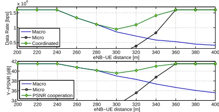
Fig. 6. Average rate and PSNR of the UE located in the eNB-UE distance intervald= [200,400]m in cooperative HetNets scenario.
better performance of the multi-rate eMBMS combined with the SVC stream as compared to the single-rate AVC-based solution (the performance loss close to the eNB is due to antenna tilt angle). The optimized resource allocation and MC assignment for the MAC-RNC-based multi-rate eMBMS is part of our ongoing work [29]. However, it is worth noting that the MAC-RNC is particularly suitable for multi-rate eMBMS solutions as it can be tightly integrated with the resource allocation and MC scheduling process residing at the MAC-scheduler, thus providing for jointly optimized solution. This is considerably harder to achieve using AL-FEC independently of the underlying LTE/LTE-A E-UTRAN protocols.
D. MAC-RNC for Collaborative Delivery over HetNets
In this subsection, we continue the unicast example from Section III-B. Within the E-UTRAN, an additional micro eNB
is introduced at the distance d= 400m from the macro eNB
(Fig. 4). We consider the same H.264/AVC video sequence
“Foreman” delivered to the UE that moves along the radial
line starting from the macro eNB and going towards the micro eNB. The stream of IP packets delivering the source sequence is forwarded from the macro eNB via the X2 interface to the micro eNB, and is synchronously processed by its own MAC-RNC sublayer to produce an independent stream of encoded packets from the same sequence of RLC packets. Note that the delay of∼1ms across the X2 interface, which is a requirement for Coordinated Multi-Point (CoMP) transmission, is sufficient for synchronized RLC PDU delivery from multiple points. Fig. 6 illustrates the data rates and PSNR values of reproduced video sequence at the UE as a function of the distancedfrom the macro eNB for cases where the UE connects to either
macro or micro eNB, or both. From d = 280 to d= 360m,
the UE may opportunistically connect to both access points in order to maintain high video quality, supported by
intra-RAN MAC-RNC coordination. From d = 360m onward,
the UE can be offloaded to the micro eNB which provides favourable channel conditions for full quality video, while releasing macro eNB resources.
IV. ADVANTAGES OFMAC-RNCFORMULTIMEDIA
DELIVERYSERVICES INLTE/LTE-A
[image:5.612.328.552.55.170.2]1) The MAC-RNC introduces redundancy only across the E-UTRAN links, using less network resources than AL-FEC that introduces end-to-end redundancy (Fig. 4).
2) The MAC-RNC that uses large field size (e.g., GF(28)) performs very close to the optimal short-length rateless codes. Given the assumption that the (progressive) GE decoding implemented within the MAC hardware should invert small
GF(28) matrices with negligible delay, the feedback delay
should be of the order of the PHY TB decoding time (∼4ms).
Thus the amount of redundancy introduced by the MAC-RNC with (almost) instantaneous feedback is close to the minimum required for variable wireless channel conditions.
3) The MAC-RNC reduces the number of feedback mes-sages to a single ACK per RLC packet while the MAC-HARQ protocol requires a (N)ACK message per MAC frame.
4) MAC-RNC coded packets may be collaboratively ex-changed by collocated UEs or forwarded by small cells (micro/femto/pico) or relay nodes in LTE-A HetNets to im-prove the media delivery process [30][31]. The “path diversity approach” for short-length RNC-coded lower-layer messages is an attractive alternative to the “time-diversity approach” for long AL-FEC coded upper-layer messages.
5) The UE may occasionally feedback the number of received linearly independent encoded packets (i.e., “received rank”) [32]. This could help the MAC scheduler to optimally allocate PHY RBs on upcoming TTIs to different UEs in order to ideally match the number of remaining coded packets required by each UE to the available system resources.
6) In the MAC-RNC framework, the RLC layer manipulates directly the IP encapsulated video packets. Thus, during RLC encapsulation, the RLC layer may exploit content-awareness that could be enabled by minimal additional cross-layer in-teraction with the application layer video coding process. For example, RLC messages may be organized into unequal importance blocks, which may be further matched by UEP version of the MAC-RNC sublayer.
V. CONCLUSIONS
In this letter, we investigated the impact of the LTE E-UTRAN-wide rateless/network coding MAC-RNC solution in-troduced in [15] on the flexibility and efficiency of multimedia delivery services over LTE/LTE-A. We demonstrated its strong potential to offer new opportunities for LTE/LTE-A E-UTRAN adaptation to packetized multimedia delivery including content awareness, UEP, close to optimal rateless delivery, novel resource allocation strategies and network coded cooperation.
REFERENCES
[1] ETSI TS 26.234 v10.2.0 (Rel. 10), UMTS-Transparent End-to-End Packet-Switched Streaming Service (PSS); Protocols and Codecs, 2011. [2] ETSI TS 26.346 v10.1.0 (Rel. 10), UMTS-Multimedia
Broad-cast/Multicast Service (MBMS); Protocols and Codecs, 2011.
[3] ETSI TS 26.247 v11.0.0 (Rel. 11), Transparent end-to-end Packet-switched Streaming Service (PSS); Progressive Download and Dynamic Adaptive Streaming over HTTP (3GP-DASH), 2012.
[4] F. Gabin, M. Kampmann, T. Lohmar, and C. Priddle: “3GPP Mobile Multimedia Streaming Standards,” IEEE Signal Proc. Magazine, Vol. 27(6), pp. 134–138, 2010.
[5] L. Haiyan, S. Ci, D. Wu, J. Wu, and H. Tang: “Quality-Driven Cross-Layer Optimized Video Delivery over LTE,”IEEE Comm. Magazine,Vol. 48(2), pp. 102–109, 2010.
[6] http://ciscovni.com/vni forecast/index.htm
[7] O. Oyman, J. Foerster, Y.-J. Tcha, and S.-C. Lee: “Toward Enhanced Mobile Video Services over WiMAX and LTE,”IEEE Comm. Magazine,
Vol. 48(8), pp. 68–76, 2010.
[8] H. Shojania, B. Li. “Random Network Coding on the iPhone: Fact or Fiction?,”ACM NOSSDAV 2009,Williamsburg, USA, June 2009. [9] P. Vingelmann, F.H.P. Fitzek, M.V. Pedersen, J. Heide and H. Charaf,
“Synchronized Multimedia Streaming on the iPhone Platform with Net-work Coding,”IEEE CCNC 2011,Las Vegas, USA, January 2011. [10] P. A. Chou, Y. Wu, and K. Jain, “Practical network coding,”Allerton
Conference 2003,Monticello, IL, USA, October 2003.
[11] G. Liva, E. Paolini, M. Chiani: “Performance vs Overhead for Fountain Codes over GFq,”IEEE Comm. Lett., Vol. 14(2), pp. 178–180, 2010.
[12] P.A. Chou and Y. Wu: “Network Coding for the Internet and Wireless Networks,”IEEE Signal Proc. Magazine,Vol. 24(5), pp, 77-85, 2007. [13] D. Vukobratovi´c, and V. Stankovi´c: “Unequal Error Protection Random
Linear Coding Strategies for Erasure Channels,”IEEE Trans.
Communi-cations, Vol. 60(5), pp. 1243–1252, May 2012.
[14] B. Schotsch, R. Lupoaie, and P. Vary: “The Performance of Low-Density Random Linear Fountain Codes over Higher Order Galois Fields under Maximum Likelihood Decoding,”Allerton 2011,USA, Sept. 2011. [15] C. Khirallah, D. Vukobratovi´c, and J. Thompson: “Performance
Eval-uation and Energy Efficiency of Random Network Coding in LTE-Advanced,”IEEE Trans. Wireless Comms,Vol. 11(12), pp. 4275-4285, December 2012.
[16] A. Khandekar, N. Bhushan, J. Tingfang, V. Vanghi: “LTE-Advanced: Heterogeneous Networks,” European Wireless EW 2010,pp. 978–982, Lucca, Italy, April 2010.
[17] 3GPP TR 36.913 V8.0.1 (Release 8), Requirements for further advance-ments for E-UTRA, March 2009.
[18] H. Holma and A. Toskala, LTE for UMTS : Evolution to LTE-Advanced, Second Edition, Wiley, 2011.
[19] A. Larmo, M. Lindstrom, M. Meyer, G. Pelletier, J. Torsner, H. Wie-mann: “The LTE Link-Layer Design,”IEEE Comms. Mag., Vol. 47(4), pp: 52-59, April 2009.
[20] T. Wiegand, G. J. Sullivan, G. Bjontegaard, and A. Luthra: “Overview of the H. 264/AVC video coding standard,”IEEE Trans. Circ. and Syst.
for Video Tech.Vol. 13(7), pp. 560–576, July 2003.
[21] T. Stockhammer, A. Shokrollahi, M. Watson, M. Luby, and T. Gasiba, “Application Layer Forward Error Correction for mobile multimedia broadcasting,” in Handbook of Mobile Broadcasting: DVB-H, DMB,
ISDB-T and Media Flo,CRC Press, pp. 239–280, 2008.
[22] J. Jin, B. Li, and T. Kong, “Is Random Network Coding Helpful in WiMAX?,”IEEE INFOCOM2008,Phoenix, AZ, USA, April 2008. [23] S. Teerapittayanon, Fouli, K.,M. M´edard, Montpetit, M.-J., Shi, X.,
Seskar, I., and Gosain, A., “Network Coding as a WiMAX Link Reli-ability Mechanism,” MACOM 2012, Maynooth, Ireland, Nov. 2012. [24] Q. Zhang, S. Kassam: “Finite-State Markov Model for Rayleigh Fading
Channels,”IEEE Trans. Comm.,Vol. 47(11), pp. 1688-1692, Nov. 1999. [25] http://www.nt.tuwien.ac.at/ltesimulator/
[26] M. Gruber and D. Zeler, “Multimedia Broadcast Multicast Service: New Transmission Scheme and Related Challenges,”IEEE Comm. Magazine,
Vol. 49(12), pp. 176-181, Dec. 2011.
[27] D. Munaretto, D. Jurca, and J. Widmer, “A resource allocation frame-work for scalable video broadcast in cellular netframe-works,”Springer Mobile
Networks and Applications,16(6), Dec. 2011.
[28] H. Schwarz, D. Marpe, and T. Wiegand, “Overview of the Scalable Video Coding Extension of the H.264/AVC Standard,”IEEE Trans. Circ.
and Syst. for Video Tech., vol. 17, pp. 1103–1120, September 2007.
[29] A. Tassi, C. Khirallah, D. Vukobratovic, F. Chiti, J. Thompson, and R. Fantacci: “Reliable Rate-Optimized Video Multicasting Services over LTE/LTE-A,”IEEE ICC 2013,Budapest, Hungary, June 2013. [30] X. Liu, G. Cheung, and C-N. Chuah, “Structured Network Coding and
Cooperative Wireless Ad-Hoc Peer-to-Peer Repair for WWAN Video Broadcast,”IEEE Trans. Multimedia,Vol. 11(4), pp. 730–741, 2009. [31] H.Seferoglu, L.Keller, B.Cici, A.Le and A. Markopoulou: “Cooperative
Video Streaming on Smartphones,”Allerton 2011,USA, Sept. 2011. [32] C. Fragouli, D. Lun, M. Medard, P. Pakzad: “Network Coding with
![Fig. 2.Average rate and PSNR of the UE located in the eNB-UE distanceinterval d = [200, 400]m in unicast macro-cellular scenario.](https://thumb-us.123doks.com/thumbv2/123dok_us/1652374.118778/4.612.60.293.240.332/average-psnr-located-distanceinterval-unicast-macro-cellular-scenario.webp)