7Institute for Theoretical Physics I, Ruhr University, Bochum D-44780, Germany 8
Institute of Applied Physics and Computational Mathematics, Beijing 100094, P. R. China
(Dated: April 13, 2014)
It is demonstrated experimentally that the presence of a long-pulse laser created backplasma on the target backside can focus the relativistic electrons produced by short-pulse laser interaction with the front of a solid target. Comparison to that without the backplasma, the number density of the fast electrons is increased by one order of magnitude and their divergence angle is reduced five fold. The effect can be attributed to the absence of the backside sheath electric field and the collimation effect of the megagauss baroclinic magnetic field there. Such a scheme could be of considerable benefit to fast ignition inertial fusion.
PACS numbers: 52.25Fi, 52.40.Mj, 52.27.Kk
Energetic electron (EE) bunches are useful for fast ig-nition in inertial fusion [1–4], realization of high energy density states [5], compact particle accelerators [7] and novel radiation sources [8], as well as in medical therapy [6]. Fast ignition, for example, demands electron ener-gy deposition at the kilojoule level inside the fuel pel-let core [1]. EE bunches produced in intense short-pulse laser-solid target interaction can have fairly high number (1014), charge (10µC), and energy (several tens joules)
[9, 10]. However, they also have a large divergence angle θd (∼30◦−50◦) and therefore are hardly applicable. It is thus essential to reduce the spatial spread of the EEs for practical applications.
Collimation of the EEs by the intense magnetic fields induced by their return currents has been proposed [11] and investigated extensively for different target designs [12, 13]. Using a prepulse to produce an azimuthal mag-netic field can also reduce the fast-electron divergence and increase the electron current density [14, 15]. On the other hand, due to the ubiquitous presence of orthogo-nal density and temperature gradients, multi-megagauss magnetic fields are easily generated baroclinically in the expanding plasma created by a long-pulse laser interact-ing with a target [16–18]. The baroclinic magnetic field (BMF) is given by∂tB=∇Te× ∇ne/nee, wheretis the time, B is the magnetic field, e, ne and Te are electron charge, density and temperature, respectively. The BMF is on a much longer timescale (few hundred ps) than that (few tens fs) of the EEs generated by intense short laser pulses.
In this Letter, we show that in the presence of a
magne-tized plasma pre-generated by a long-pulse laser imping-ing the backside of the target, the intrinsically divergent EEs that have passed through the target can be collimat-ed by the toroidal BMF. The backside plasma also allows the EEs to propagate more stably and suppresses the for-mation of the target normal sheath electric field there by partially neutralizing the less energetic hot electrons from the target front. As a result, a tight EE bunch with high energy and charge densities can be produced. The pro-posed process is schematically illustrated and discussed in Fig. 1(a).
To bend the trajectory of a fast electron of speedv at an angle θd with respect to the axial (z) direction, the magnetic field should satisfy [14]
BϕLr≥ γvme
e S, (1)
where me is electron mass, Lr is the scale length of the transverse (r-direction) magnetic field, γ = (1 − v2/c2)−1/2is the Lorentz factor, and S= 1−cos (θ
d/2). For a fast electron generated at the front side of the tar-get by the main laser pulse of intensityI0and wavelength
λ0, the factorγvis determined by the corresponding
pon-deromotive force [17]. Accordingly, the condition for de-flecting the divergent electron towards the axial direction can be written as [14]
BϕLr≥ mec
e
√
1 + I0λ
2 0
1.38×10¹⁸Wcm−2µm2S, (2)
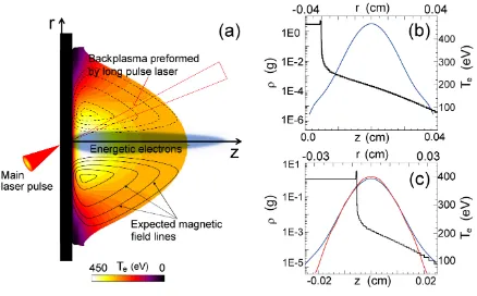
namic simulations of the interaction of a long-pulse laser with the backside of a planar Al target. The contours (thin black closed curves) depict the expected toroidal baroclinic mag-netic field, which is peaked around the edge of the laser focal spot and decreases to zero on the axis (r = 0) and at large distances from the focal spot. The EEs (blue region) created and accelerated by the targetfront laser are focused into a nar-row bunch by the strong magnetic field. The hydrodynamic simulation results for the backplasma electron density (black) along thez axis, and temperature (blue) along ther at the position of 0.01 cm away from rear surface of the target, are shown in (b) for the Al target with flat backside, and (c) for two plastic targets with different backside curvatures (blue: infinite, and red: 2.5 mm).
We use the radiative hydrodynamics code MULTI2D [20] to simulate the laser-excited plasma expansion and magnetic field generation at the target backside. In ac-cordance with the experimental parameters, a 2 J p -polarized 1.053µm 400 ps long laser pulse is focused on a 50 µm-thick Al target with a∼ 300 µm spot diame-ter. Fig. 1(b) shows that the electron density gradient is mainly in the axial direction, as expected. Thus, the axial temperature gradient does not contribute to the BMF generation. The magnitude of the BMF is then roughly given byB0∼Tet/lnlT, whereln andlT are the scalelengths of the density and temperature, respective-ly. For Te ∼ 400 eV, ln ∼ 10 µm, and lT ∼ 150 µm (estimated from Fig. 1(b)), we find that the magnetic field attains 1 MG in 400 ps. For 200 µm-thick plastic targets with different targetback curvatures, our simula-tions show almost no difference in the axial profiles of the plasma density. On the other hand, the radial tem-perature gradient increases with the curvature since the plasma is transversely better confined, as shown in Fig. 1(c). Accordingly, with a BMF ∼ 1 MG in the back-plasma of Lr ∼ 150 µm, the collimation condition (2) is readily satisfied for EEs driven by a I0λ20 = 5×10¹⁸
Wcm−2µm2main laser pulse and exiting the target back
withθd∼50◦.
Collimation of the EEs in the intense laser interaction
FIG. 2: (Color online.) Experimental setup (a). Observed an-gular distribution of electrons over 0.4 MeV for planar Al tar-get with (b) and without (c) preformed plasma on the back-side. The p-polarized main laser pulse defining the angular direction (0◦,0◦) is incident obliquely at a 20◦ angle on the front surface of the target (such that the target normal is in the (20◦,0◦) direction. (d) Number of> 0.4MeV electrons along the grey dashed lines in the panels (b) and (c).
at the target front are tested for both planar Al target-s and platarget-stic targettarget-s with concave back target-surfacetarget-s on the GEKKO Module II laser system at the Institute of Laser Engineering, Osaka University. The experimental set-up is shown in Fig. 2(a). After a 400 ps time delay for preplasma formation at the back surface by a long-pulse laser, EEs are generated at the flat target front surface at an 20◦ incident angle by a p-polarized 10J 1.053 µm 0.6 ps short-pulse laser. The laser pulse is focused by an f/3.8 off-axis parabolic mirror into a 20µm diameter spot with peak intensity∼ 5×10¹⁸ Wcm−2. To probe
the energy-resolved angular distribution of the EEs along the axis of the main laser, a sandwich detector is placed
∼ 4cm away from the targetback. It consists of four layers of photo-stimulated-luminescence (PSL) imaging plates (IPs) with in-between copper filters for detecting 0.4 MeV, 3 MeV, 6 MeV, and 10 MeV electrons. A ra-diochromic film (RCF) layer and a CR-39 layer in front of the IPs are used to monitor the angular distribution of energetic protons. A 10µm thick Al foil is placed in front of the detectors to shield them from the target de-bris. The entire detector system is wrapped with black tapes and Al foils to block stray light. Tests showed that the small number of protons from target normal sheath acceleration can be completely stopped from arriving at the IPs by the RCF and CR-39 layers.
The angular distribution of the EEs behind a plain Al target without a preformed backplasma is shown in Fig. 2(b). We see that the electrons are of low density (8×10⁸)
[image:2.595.325.550.52.234.2] [image:2.595.66.285.58.194.2]FIG. 3: (Color online.) Experimental angular distributions of energetic electrons over 0.4 MeV for different cylindrical target back curvatures: (a) infinite (or planar), (b) 5.0 mm, and (c) 2.5 mm, for 200µm×(5×5 mm2) plastic targets. The
curvature axes in (b) and (c) are perpendicular and parallel, respectively, to the laser polarization. (d) Electron number (obtained from the sandwich detector using photo stimulated luminescence) along the dashed lines in Figs. 2(b), 2(c), 3(a), 3(b), and 3(c), denoted by 2b, 2c, 3a, 3b, and 3c, respectively.
more than 50◦around the laser axis at 0◦. Fig. 2(c) shows that, in the presence of a performed plasma behind the target, the electrons are much more uniform and of much higher density (1.2×10⁹). They are also much better collimated, with the average angular spread reduced to
∼ 30◦. It should be mentioned that despite their near axial direction and narrow spread, the mean direction of the EEs varies somewhat from shot to shot, which can be attributed to uncertainties in the configuration (which determines the focusing direction) of the self-generated magnetic field.
In order to see in more detail the effect of the backplas-ma and the self-generated backplas-magnetic field, we have also considered plastic targets with different concave back sur-faces. As discussed, the latter determines the backplas-ma density and temperature as well as their gradients, and therefore also the self-generated BMF. The results are shown in Fig. 3. One can see that as the curvature radius is reduced from infinite (a) to 5 mm (b) to 2.5 m-m(c), the spatial spread of the EEs becomes smaller and their number density higher. Similar to that for the flat Al target, the deviation of the EEs from the exact axial direction of the main laser is due to uncertainty in the configuration of the baroclinic magnetic field.
For comparison, Fig. 3(d) shows the electron number along the dashed lines for the five cases in Figs. 2(b) and 2(c) and 3(a) - 3(c). We see that the electrons behind the curved target backs are much better collimated. Their number is also more than one order of magnitude high-er than that behind the flatback targets. These results
FIG. 4: (Color online.) Results from 2D PIC simulations at t = 80 laser periods from the laser impact: magnetic field distribution (left column), distribution of >1 MV energet-ic electrons (center column), and electron density atx= 30 µm (right column), forB0 = 0 MG (top row),B0 = 5 MG
(center row), andB0 = 10 MG (bottom row). The 5 µ
m-thick solid-density (20nc, wherenc= 1.1×10²¹/cm3) target
is at 5< x[µm]<10. Note that the magnetic fields associ-ated with the laser-target interaction and energetic-electron filamentation are relatively much stronger and localized than the prescribed megagauss model baroclinic magnetic fields, appearing as large blue and red shaded regions in (d) and (g).
represent a significant improvement over that of the ex-iting experiments [20]. In fact, Figs. 3(a) and 3(c) show that the divergence of the EEs is reduced from about θd ∼ 30◦ for the flatback target to about θd ∼ 10◦ for the curveback targets. Moreover, the number density in the center region is increased fivefold. We note that if all the EEs in the original 30◦divergence angle were focused into the 10◦ divergence angle, the density enhancement factor would be∼ 9.5, which is larger than the experi-mental value∼5.0. The discrepancy can be attributed to filamentation [22, 23] of the fast EEs as they propa-gate in the underdense region of the backplasma, since some electrons are scattered away from the EE bunch, as can be seen in Figs. 3(b) and 3(c).
[image:3.595.326.552.50.338.2] [image:3.595.64.290.50.232.2](appearing only as red and blue colored shades in Figs. 4(d) and 4(g)) behind the target. However, the former fields are not directly of our interest here.
In Fig. 4 we can see that filamentation of the EEs oc-curs as they exit the rear side of the target, and in the absence of the BMF the filaments, together with their induced magnetic fields, are highly divergent. AsB0
in-creases, the electron filaments, or the electron jets as a w-hole, become better collimated and focused, even though they appear to be locally unstable to kink or sausage type instabilities and tend to breakup and then coalesce the originally thin filaments, as can be seen in Fig. 4, right column, for the line profiles of the EE density atx= 30 µm. We can also see that, because of improved focusing, the peak EE number density is enhanced by a factor of about 4 as B0 increases from 0 to 10 MG. Except for
the precise location (unpredictable in the experiments) of the peaks, these simulation results agree qualitatively well with that (Fig. 3(d)) from the experiments.
In summary, focusing of relativistic laser generated EEs from the front of a solid target by the BMF in a backplasma created at the target backside by a long pulse laser is demonstrated experimentally and by PIC simulations. The EEs, originally with large divergence angle (θd ∼50◦), are collimated into a tight bunch with θd ∼ 10◦ as they propagate in the backplasma. The focusing and collimation are shown be effected by the strong BMF generated by the nonparallel density and temperature gradients in the backplasma. The estimat-ed condition for collimation and the results from the PIC simulations for the process agree reasonably well with that from our experiments. The proposed scheme pro-vides a simple and effective way for collimating a large number of initially highly divergent EEs, such that an electron bunch of high energy and charge densities can be produced.
This work is supported by the National Research Program of China (2013CBA01504), the Nation-al NaturNation-al Science Foundation of China (11175253, 91230205, 11275269, 11205194, 11247007, and 11374262, 11220101002), the Research Program of NUDT,
ITER-[3] R. Kodama, P. A. Norreys, K. Mima, A. E. Dangor, R. G. Evans, H. Fujita, Y. Kitagawa, K. Krushelnick, T. Miyakoshi, N. Miyanaga, T. Norimatsu, S. J. Rose, T. Shozaki, K. Shigemori, A. Sunahara, M. Tampo, K. A. Tanaka, Y. Toyama, T. Yamanaka, and M. Zepf, Nature
412, 798 (2001).
[4] R. Kodama, H. Shiraga, K. Shigemori, Y. Toyama, S. Fujioka, H. Azechi, H. Fujita, H. Habara, T. Hall, Y. Izawa, T. Jitsuno, Y. Kitagawa, K. M. Krushelnick, K. L. Lancaster, K. Mima, K. Nagai, M. Nakai, H. Nishimura, T. Norimatsu, P. A. Norreys, S. Sakabe, K. A. Tanaka, A. Youssef, M. Zepf, and T. Yamanaka, Nature418, 933 (2002).
[5] R. Kodama, Y. Sentoku, Z. L. Chen, G. R. Kumar, S. P. Hatchett, Y. Toyama, T. E. Cowan, R. R Freeman, J. Fuchs, Y. Izawa, M. H. Key, Y. Kitagawa, K. Kon-do, T. Matsuoka, H. Nakamura, M. Nakatsutsumi, P. A. Norreys, T. Norimatsu, R. A. Snavely, R. B. Stephens, M. Tampo, K. A. Tanaka, and T. Yabuuchi, Nature432, 1005 (2004).
[6] S.V Bulanov, T.Zh Esirkepov, V.S Khoroshkov, A.V Kuznetsov, and F. Pegoraro, Phys. Lett. A 299, 240 (2002).
[7] H. B. Zhuo, Z. L. Chen, W. Yu, Z. M. Sheng, M. Y. Yu, Z. Jin, and R. Kodama, Phys. Rev. Lett. 105, 065003 (2010).
[8] Z. Jin, Z. L. Chen, H. B. Zhuo, A. Kon, M. Nakatsutsumi, H. B. Wang, B. H. Zhang, Y. Q. Gu, Y. C. Wu, B. Zhu, L. Wang, M. Y. Yu, Z. M. Sheng, and R. Kodama, Phys. Rev. Lett.107, 265003 (2011).
[9] J. S. Green, V. M. Ovchinnikov, R. G. Evans, K. U. Akli, H. Azechi, F. N. Beg, C. Bellei, R. R. Freeman, H. Habara, R. Heathcote, M. H. Key, J. A. King, K. L. Lancaster, N. C. Lopes, T. Ma, A. J. MacKinnon, K. Markey, A. McPhee, Z. Najmudin, P. Nilson, R. Onofrei, R. Stephens, K. Takeda, K. A. Tanaka, W. Theobald, T. Tanimoto, J. Waugh, L. Van Woerkom, N. C. Woolsey, M. Zepf, J. R. Davies, and P. A. Norreys, Phys. Rev. Lett.100, 015003 (2008).
[10] K. L. Lancaster, J. S. Green, D. S. Hey, K. U. Akli, J. R. Davies, R. J. Clarke, R. R. Freeman, H. Habara, M. H. Key, R. Kodama, K. Krushelnick, C. D. Murphy, M. Nakatsutsumi, P. Simpson, R. Stephens, C. Stoeckl, T. Yabuuchi, M. Zepf, and P. A. Norreys, Phys. Rev. lett
98, 125002 (2007).
[16] J. A. Stamper, K. Papadopoulos, R. N. Sudan, S. O. Dean, and E. A. McLean, Phys. Rev. Lett. 26, 1012 (1971).
[17] O. Willi, P. T. Rumsby, and C. Duncan, Opt. Commun.
37, 40 (1981).
[18] M. Borghesi, A. J. MacKinnon, A. R. Bell, R. Gaillard,