DESIGN AND DEVELOPMENT OF A
COMPETITIVE
liIR£ SPLICIN6
SYSTEM
FOR
TH£
AUTOMOTIV£
WIRE
HARNESS INDUSTRY
A thesis presented in partial fulfilment of the requirements for the
award of
M.Tech
In Manufacturing And Industrial Technology
Department of Production Technology, Massey
University, Palmerston North, New Zealand
ABSTRACT
The work presented in this thesis is aimed at developing a very comprehensive system of manufacturing wire splices for automobile wire harnesses. Ultrasonic welding is increasingly being used in various industrial applications. Lack of a scientific data-base of its properties when applied to wire splicing is a major reason for lack of proper usage by the wiring harness industry and its subsequent acceptance by the end user. This thesis presents various experiments conducted to develop tensile strengths and electrical resistances of various types of ultrasonically welded wire splices. Crimping technology was evaluated for its mechanical strengths and electrical properties by conducting various experiments to make it possible for the industl)' to compare it with other alternative splicing technologies. The results are then compared with ultrasonic welding.
The next stage of this thesis discusses the economic feasibility of ultrasonic wire splicing. In order to find the number of ultrasonic welding machines required to meet a particular level of demand, which is a prerequisite for establishing the economic feasibility, a virtual model of the process and the manufacturing cell has been prepared and this model was used to study the dynamics of demand and the number of required machines. Simulation in manufacturing-problem-solving is being used very widely by researchers. Proper understanding and visualisation of the future of the factory and understanding and answering various questions related to the adoption of new technology, is another major reason why companies shy away from adopting ultrasonic welding systems. An advanced simulation tool namely QUEST was used to model the wire splice manufacturing cell of Alcatel and simulation studies were conducted to foresee how the production dynamics would be if ultrasonic welding machines were incorporated in place of crimping machines and various what if scenarios were developed and some vital production related questions were answered.
Material handling is a major bottleneck in any wmng harness manufacturing environment. Some conceptual designs are presented on automating the task of feeding wires to ultrasonic welding machines and transferring the wire assemblies from welding stations to different work stations, currently being done manually. A wire palletising
system was designed to improve the productivity. ·
Acknowledgments
My deep sense of gratitude and apprec1at10n to Dr. Saeid Nahavandi, academic supervisor of this thesis, for his valuable contribution. Besides being the academic supervisor of this project, he was also my personal mentor. It would not have been possible for me to have completed this project without his drive, direction and personal motivation. His technical contributions to the project have made this project very meaningful to the Industrial collaborator and the funding bodies. He has been with me right through the project advising me at every possible opportunity. My close family join me in thanking Dr. Nahavandi for all the personal help extended to us during our stay in Palmerston North and later on in the completion of the thesis after moving to Auckland.
Graeme Wild of Alcatel New Zealand, has contributed enormously to the successful completion of this project. Without his consistent help, it would not have been possible to complete the project. His help and contributions are highly appreciated and I sincerely thank him.
I would like to acknowledge the sincere interest shown by Bryant O'Neill of Alcatel New Zealand, without which the project would not have completed meaningfully. His direction and technical contributions are highly appreciated. My sincere thanks to him.
I thank all the above three individuals for their time, efforts and interest in this project. I thank them for everything they have done personally and otherwise.
I am very grateful to the Department of Producti.on Technology, Massey University for the financial assistance and the resources provided for my M.Tech programme. I am very thankful to the Foundation for Research, Science and Technology for the financial assistance provided through the Graduate Research in Industry Fellowship programme.
My sincere thanks to Dr. Ted Smith, Phil Collins, Farshad Nourozi and Dr. Ibrahim Al-Bahaldy, for their advice and technical assistance.
. ·. . .
. I would like to express my thanks to Adam Waldron, who has helped me in conducting many experiments, through his B.Tech final year project.
I would like to thank all the engineering staff at Alcatel, Masterton, for their help. I acknowledge, especially, the help provided by Dave Smith.
I acknowledge my fellow students' help, especially Ajay Talla, Siva Kankanala, Dennis Wai, Venkat Ananthula and Mathew Jolly. Other students like Tammi Tan, Nigel Russell, Jeoff Foot, Ravi Dixit, Naeem Jan, Murali Guntur, Dilip Chirala, Paul Solomon, Nigel Yee, Venkat Karla, Kamaljit Singh, Mathew Harris and many others have helped me on many occasions. I thank every one for their help.
I very sincerely acknowledge the love, affection and help extended by my parents
Krishna and Savithri. It wouldn't have been possible for me to have come to New Zealand and complete this project without their guidance and help.
I thank my little daughter Chandana for being very patient and quiet throughout my
thesis preparation.
Contents
ABSTRACT ·- - - 2
1. INTRODUCTION TO THE THESIS AND OBJECTIVES OF THE RESEARCH PROJECT-10 1.1 lNTIWDUCTION TO THE WIRlNG HARNESS INDUSTRY ---10
1.1.1 The wiring harness manufacturing process 11 1.2 WIRE SPLICING ---13
1. 3 OBJECTIVES OF THE PROJECT---13
1. 4 lNDUSTRlAL COLLABORATION --- 14
1. 5 PREVIEW OF THE THESIS --- 14
2. WIRE SPLICING FOR AUTOMOTIVE WIRING HARNESSES- SOME FUNDAMENTAL COMP A RISO NS ---17
2.1 ME1HODS OF MANUFACTURJNG THE WIRE SPLICES ---17
2.1.1 Crimpi11g 17 2.1.2 Resistance w e l d i n g - - - - 18
2.1. 3 Ultrasonic welding---19
2.2 ULTRASONIC WELDING-DEFINITION AND GENERAL DESCRIPTION ---22
2. 3 MECHANISM OF THE PROCESS--- 23
2.3. I Stress patterns 23 2. 4 TEMPERA TIJRE DEVELOPED IN WELD ZONE --- 24
2. 5 ENERGY DELIVERED TO THE WELD ZONE--- 25
2.6 POWER REQUIREMENTS AND WELDABILITY ---25
2. 6. I We Ida bi Ii ty of copper alloys ---2 6 2. 7 Lii'vITT A TIONS---2 6 2. 7. I Thickness 26 2. 7.2 Geometry--- 26
2. 8 APPLICATIONS IN THE WIRlNG HARNESS INDUSTRY---2 7 2.8. I Electrical connectio11s--- 27
2. 8. 2 Encapsulation ---2 7 2. 9 PROCESS VARIABLES---27
2.9. I Ultrasonic power---2 7 2.9.2 Clampingforce--- 28
2.9. 3 Welding time or speed 28 2.9.-1 Frequency adjustments 28 2.9.5 Interaction of welding variables 28 2.10 ADV ANT AGES AND DISADVANTAGES ---29
3. BENCHMARKING THE CRIMPING TECHNOLOGY---32
3. l DESIGN CONSIDERATIONS --:---~---3 2 3.1.1 The joint . 32 3.1.2 Fero/es· 33 3.1.3 Wires 33 3.2 STRENG1H OF THE J O I N T S - - - 3 3 3.2.J Mechanical aspects 34 3.2. l.l Types ofloads the joint is subjected to---34
3.2.1.2 Modes offailure of the ferruled joints--- 35
3.2.2 Electrical aspects 35 3.2.2. l Modes of electrical failure --- 35
3.3.l Sample preparation for testing 37 3. 3. l. l Length of wire strands: --- 3 7
3.3. l.2 Amount of insulation sheath to be stripped off on either sides of the wires--- 38
3. 3. 2 Findings from the trial experiments 38 3.3.2. l Gripping---38
3. 4 STIJDY OF MECHANICAL PROPERTIES---39 3. 4.1 Objectives of the experiments 39 3.4.2 Theory of the experiments 39 3.4.3 Apparatus used in the experiment 40 3 .4. 3. l Machine settings --- 41
3.4.4 Standards used in the experiment--- 41
3.4.5 Test procedure adopted---- - -------------- 41
3.4.6 Experimental results 41 3. 5 STIJDY OF ELEClRICAL PROPERTIES ---42
3.5. J Objectives of the experiments 42 3. 5. 2 Theory of the experiments
---
---
--
----
---
---
---4
2 3.5.3 Apparatus used in the experiment 42 3. 5.4 Standards used 4 2 3.5.5 Procedure used 42 3.5 .5 .l Repeatability of the experimental conditions---433.5.6 Experimental results- 43 3 .6 DISCUSSION AND ANALYSTS OF RESULTS--- - - - 4 3 3.6. 1 Tensile strength as a variation of joint cross-sectional area 43 3.6.2 Electrical resistance as a variation of joint cross-sectional area---16
3.6.3 Tensile strength and electrical resistance when the crimp height is varied 46 4. ULTRASONIC WELDING OF COPPER WIRE SPLICES ---53
4. l UL TRASONlC WELDING ---53
4. 2 TECHNICAL FACTORS INVOLVED IN TI IE STUDY ---53
4. 3 EXPERIMENT AL DESIGN AND STUDY ---54
-1.3. 1 Sample preparation for testing--- 55
4. 4 STUDY OF MECHANICAL PROPERTIES---5 5 -1..1. 1 Objectives of the experiments 55 4. 4. 2 Theory of the experiments
-
---55
-1.4.3 Apparatus used in the experiment 56 4. 4.3. l Machine settings ---56
4. 4. 4 Standards used in the experiment 56 4.4.5 Test procedure adopted 56 -I. 4. 6 Experimental results-------- 56
4. 5 STUDY OF ELECTRICAL PROPERTIES --- - - - -57
5. I. I Comparison of failure loads 63
5.1.2 Comparison of tensile strengths---6-1
5.2 ELEC1RICAL PROPER11ES ---65
5.2.1 Compariso11 ofresisla11ce offered by i11dividual cross-sectional samples---65
5 .3 DIMENSIONAilGEOMETRICAL PROPERTIES--- 6 7 5.3.l Failure modes under tensile loads 68 5.3.1.1 Modes of failure of crimped connections--- - - - --- 68
5.3. J .2 Failure modes of ultrasonic connections --- 7 J 6. IMPLEMENTATION OF ULTRASONIC WELDING- CONSIDERATION OF SOME PRODUCTION DYNAMICS - - - 76
6. 1 SIMULATION STIJDY ---7 6 6.1.1 Objectives of the study--- - - - -76
6.1.2 Selection of Queuing Event Simulatio11 Tool (QUEST)!Features of QUEST 77 6.2 SIMULATION s·nmy APPROACH--- 78
6.2. l Experimental Procedure 79 6.2.2 Problem definition 80 6. 2. 3 Data collection and definition of plan of action for solution ---80
6.2.4 Verification of data--- ---82
6.2.5 Model -1 -Curre11I mcnmfacturingfacilities with crimping machines 82 6.2.6 Simulation of specific commercial order--- ---83
6. 2. 7 Modification of the model made until the model reached a satisfactory condition of exactly mimicking the existing mcn111facturi11gfacilities - - - - - - 8 3 6.2.8 Model-2 -Proposed manufacturing facilities with ultrasonic welding machines 8-1 6. 2. 9 Simulation of specific commercial production order 8./ 6.2.10 Defi11itio11 of steady state and its boundaries
---
-
---
-
----8./
6. 2.11 Modification of model data - - - - 85
6.2.12 Pe1jormance indicators--- 86
6.2.12.1 Throughput time--- 86 6.2.12.2 Average buffer-length--- 86 6.2.12.3 Average Residence time --- 86
6.2.12.4 Maximum Waiting time --- 86
6. 3 RES UL TS---8 7 6.4 DISCUSSION OF RESULTS ---87
6 . ./.1 Throughput time - 8 7 6 . ./.2 Average buffer length ---~------88 6 . ./. 3 Average reside11ce times 89 6.4 . ./Maximum waiting t i m e - - - - - 90
6. 5 FURTIIER WORK ---90
6. 6 RECOMJ'\.1ENDA TIONS---91
6. 7 COST BENEFIT ANALYSIS --- 91
7. IMPLEMENTATION OF ULTRASONIC WELDING - CONSIDERATION OF SOME AUTOMATION ASPECT 95 7.1 OBJECTIVES OF THE STIJDY--- . - - - 9 5 7.2 OPERATIONS---97
7.3 PROBLEMS ASSOCIATED WITIIlN THE CURRENT SYSTEM 97 7. 4 PROPOSED HANDLING SYSTEM ---98
7. 5 CONCEPTIJAL DESIGNS--- 98
7.5.1 Wire pal/etiser 98 7 .6 CONVEYOR FOR PALLET MOVEMENT --- 101
7. 7 POSSIBLE ADV ANf AGES OF THE PROPOSED SYSTEM - - - 101
CONCLUSIONS 104
BIBLIOGRAPHY 106
1.
INTRODUCTION
TO
THE
THESIS
AND
OBJECTIVES OF THE RESEARCH PROJECT
Introduction
This chapter gives an overview of the current state of affairs of the wiring harness industry. After having established the back-ground of this research, an introduction is given to the current methods of manufacturing wiring harnesses. This research was carried out for Alcatel New Zealand Limited, the industrial collaborator for this activity.
1.1 Introduction to the wiring harness industry
Electrical wiring harness can be visualised as a kind of nervous system of many electrical systems in which it finds its place, with the mantle of reliably and efficiently transmitting the power falling on it. There are over 160 manufacturers of
wire harnesses and fabricated lead wires for passenger auto, truck and other
commercial and industrial vehicle applications in the world today [1]. There are many other major industries including white goods, brown goods, office/electronic data processing, control and industrial electronics, aerospace and others accounting for a multi billion dollar market world \vide.
With today's advanced automotive control systems, manufacturers of electrical harnesses for vehicle use are faced with even more stringent requirements for reliable connections in their automotive harnesses, with the other industries the case being no different and far more demanding in some industries like aerospace. IncreasLng demands for on-board sensors and microprocessor controls create a need to achieve flawless wire terminations capable of reliably transmitting low-voltage signals. Even the slightest variation in resistance across a circuit will create havoc. In addition to the quality control by the various industries, there is an increasing emphasis on overall weight reduction of vehides. A typical wiring harness assembly amounting to about 100 lbs, is a major area for considering weight reductions [l].
Furthermore, the manufacturing of cable harnesses and networks has, using traditional methods , been an extremely costly, labour intensive and monotonous process. Methods used to construct cable harnesses have necessitated long lead times, large series and a substantial amount of tied up capital. The cost of producing and installing cable harness represents a large proportion of the total manufacturing cost of any electrical system. For example, the cost associated with cables in a modem car. represent the second largest item, after the engine but before the bodywork [2].
harnesses.
It is high time for the New Zealand wiring harness industry to look at not only improving productivity but to drastically reduce the cost of manufacturing to compete in new markets. Besides the cost, a better quality and appearance to the product is a major thrust for the industry's success in the future.
1.1.1 The wiring harness manufacturing process
The most common method of manufacture, being adopted currently by the majority of the industry, is presented below.
The different operations involved in the manufacture of the wiring harness could be easily understood by looking at typical operations identified as following:
0
6
-~
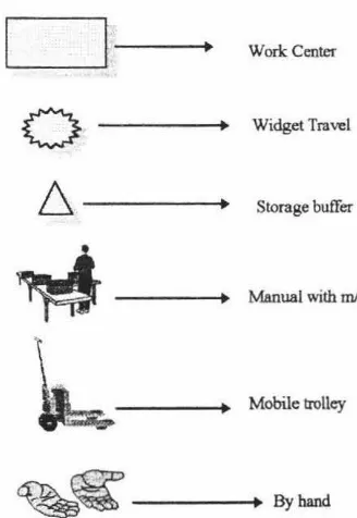
l.-Work Center
Widget Travel
Storage buffer
Manual with role
Mobile trolley
[image:12.555.233.397.357.595.2]~~
--
Byhand
Figure 1-1, Legend to the system description
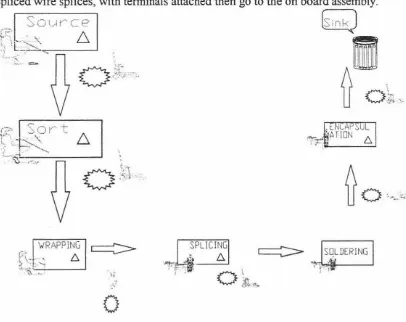
The system flow chart described below, uses the legend of various operations in the above Figure.
• Sorting is where, the wires are grouped on the information available from their
route cards and sorting decides where the wires would go next.
• Wrapping is where the wires are individually wrapped to conform to the drawing
of a specific joint that the wires are supposed to form.
• The next operation is where the wires are spliced before they go for joint encapsulation, where the joints are wrapped with insulation.
Wires coming from the storage facilities are cut to the desired lengths and stripped, ie., the insulation sheath at the wire ends are removed. This is made on one machine ie., the cutting and stripping is done in single stroke on one machine. The insulation at the wire ends is removed to facilitate the placement of other electrical terminals. This piece, known as "lead" goes further in the series of operations to get joined with other leads, then called J-lead, or may as a single lead go downstream.
In the next step of operations the electrical terminals are attached to the leads or
J-leads by crimping machines . The other possible operations on these leads could be of sleeving or connector assembly.
Some cables need to be joined or spliced together to form a joint, known in the industry jargon as "internal join". This could be a down stream operation after the termination, sleeving or it could be a direct downstream from the cut and strip. These spliced wire splices, with terminals attached then go to the on board assembly.
Sourc
e
fu
in
k.)
~
~
:_;__'
6
i
v ..,,..
o
.~t.·.
.
/\
U
o
~
~
,,.
VRAPPING
f~> -... .
'
b. ~ "i'-.-. _ _ __.0
SPLICING
b.
JENCAPSOL
I
[image:13.556.42.448.394.716.2]~ ATION b.
1.2 Wire splicing
Wiring harnesses typically contain several splice junctions of multiple wires. The number of splice junctions (in other terms called wire splices) coming in a wiring
harness vary typically with the size and design of the harness. Nevertheless,
irrespective of the number of wire splices, they are like nodal points prone to mechanical, electrical and chemical failures [6]. The overall reliability of the wiring
harness, undoubtedly, depends on the reliability of the wire splices.
There are three major methods [3] of making the splices; the cnmp method,
resistance welding and ultrasonic welding, explained in section 2.1.
1.3 Objectives of the project
The objectives set out for this project, which was sponsored by The Foundation For
Research, Science and Technology (FRST), Government of New Zealand, under the Graduate Research in Industry Fellowship (GRJF) [45], were:
• Evaluate the crimping technology, currently being used by many wiring harness
manufacturers, to manufacture the wire splices. This was to be done by quantifying
the electrical and mechanical properties.
• Study other alternative techniques of producing the wire splices and identify the one which is technically and otherwise superior among all the alternative
techniques.
• Evaluate the identified alternative technique for its electrical and mechanical
strengths, when used for wire splicing.
• Compare the crimping technique with the alternative technique on electrical and
mechanical strengths and weaknesses.
• Help the industry in adopting the technology in the right technical form and help them in implementing the technology, to make it successful. Implementation of the technology is again divided into two sections:
1. Study the effect of the new technology on the production dynamics of the industry. Specifically on the factors like how the new technology would cope with the fluctuations in demand and other important production related factors. This was envisaged to be made by developing simulation models of the future plant,
industry.
2. Study the manufacturing ·aspects of the technology and come up with some
solutions to some of the material handling problems. This was to be made by
identifying the problems currently being faced and then come up with some
conceptual solutions in terms of automatic part presentation systems and part
transfer systems and produce a conceptual design.
1.4 Industrial collaboration
This project is made in industrial collaboration with Alcatel New Zealand Limited, a
leading automotive wiring harness manufacturer in New Zealand.
Alea tel is one of the world's largest manufacturer and supplier of telecommunications
equipment. Alcatel New Zealand is a major supplier to Telecom, providing locally
designed and manufactured telephones and other sophisticated hardware and software
products. Submarine optical fibre cable systems, printed circuit boards and wiring
harnesses for the automobile industry are among the other products manufactured at
the Alcatel's manufacturing plants in Masterton and Upperhutt [4].
This project was based at the Masterton plant which is concerned solely with the
processing of electric cables into wiring harnesses for the automobile industry. The
majority of these harnesses are manufactured for domestically assembled cars and
commercial vehicles.
1.5 Preview of the thesis
In this section a brief overview of what is being presented in various chapters is
discussed.
Chapter-2, presents the fundamental introductory discussion of different types of wire splicing techniques and a relative comparison is made between the three known types, viz., crimping, resistance welding and ultrasonic welding.
In Chapter-3 an attempt is made to bench mark the crimping technology, which is by
far most widely used for making crimped wire connections. Experiments, which have been carried-out to quantify the mechanical and electrical strengths, are discussed and the results are presented.
Chapter-4, discusses the technique of making wire connections with ultrasonic welding. Quantification of the electrical and mechanical strengths have been made in this chapter.
ultrasonically welded connections. Electrical and mechanical properties are
compared, besides a comparison of other factors such as the splice volume,
appearance, modes of failure etc., is also made.
Economic feasibility of ultrasonic welding is discussed in chapter-6. A virtual model has been presented as a tool to study the dynamics of production and an attempt is made to use this to establish of economic feasibility.
How ultrasonic wire splicing could be implemented in an industrial environment,
where crimping is the current method of splicing, is discussed in chapter-7.