Lucy Bull, Eric J. Palmiere, Richard P. Thackray, Ian W. Burgess and Buick
Davison
Reprinted from
Journal of
Structural Fire
Engineering
Volume 6 · Number 3 · September 2015
Tensile Behaviour of Galvanised
Grade 8.8 Bolt Assemblies in Fire
Lucy Bull*a, Eric J. Palmiereb, Richard P. Thackrayb, Ian W. Burgessc andBuick Davisonc
aTinsley Bridge Group, formerly Lucy Johnson, Department of Materials Science and Engineering,
The University of Sheffield, UK
bDepartment of Materials Science and Engineering, The University of Sheffield, UK cDepartment of Civil and Structural Engineering, The University of Sheffield, UK
ABSTRACT
In structural fire engineering, the importance of bolt assemblies is often overlooked. Connection design uses the temperature-dependent bolt strength-reduction factors prescribed in Eurocode 3, despite the existence of two distinct failure modes under tension; necking of the bolt shank, and thread-stripping. While literature exists to predict failure modes at ambient temperature, there is no method for failure mode prediction for elevated temperatures where ductility is critical to avoid collapse. Galvanised M20 structural bolt assemblies and bolt material from a single batch have been tested under tension at a range of temperatures and strain-rates typical of those experienced in fire. Turned-down bolt test data produced stress-strain curves characteristic of different microstructures at ambient temperature, despite a tempered-martensitic microstructure being specified in the standards. The failure modes of bolt assemblies were found to be dependent on the as-received microstructure at ambient temperature. At elevated temperatures, however, only thread-stripping was observed.
Keywords:Bolt assemblies, ductile and brittle failure, thread stripping, microstructure
1. INTRODUCTION
This paper examines the tensile behaviour of bolt material, in the form of turned-down bolts, and bolt assemblies, at a range of temperatures and strain-rates. A single batch of galvanised M20 structural bolting assemblies, in accordance with BS EN 15048 [1], were chosen, as they are commonly used in UK construction. The bolts were Grade 8.8, while the pairing nuts were of Property Class 10. The bolt assemblies were donated by a UK distributor; which had imported the components, carried out quality assurance testing and applied its own manufacturers mark. This is common practice in the UK, where all structural bolts are currently imported due to the high cost of raw materials [2]. According to ISO 898-1 “A distributor who distributes fasteners that are marked with his (or her) own identification mark shall be considered to be the manufacturer” [3], which makes the original overseas manufacturer untraceable. The strength reduction factors provided in Table D.1 of Eurocode 3 [4] came directly from the results of testing carried out during the 1990s on bolt assemblies manufactured in the UK [5, 6]. At the time at which this research was carried out ‘structural’ bolting assemblies did not exist. All nuts and bolts could be purchased individually and interchangeably. Quality assurance testing, therefore, did not include the mechanical testing of the assembly as a whole. Geometrical differences also exist between the bolts tested by Kirby [5, 6] and those discussed in this paper. Kirby tested assemblies of looser thread tolerance class combinations, known as 7H8g, as specified in BS 4190 [7]. However, the assemblies tested in this paper are of the tighter tolerance class 6AZ6g, as specified in ISO 965-5 [8] and ISO 4032 [9]. The equivalent tight tolerance class for uncoated assemblies is 6H6g, as specified in ISO 4017 [10] for fully-threaded bolts or ISO 4014 [11] for partially-threaded bolts, and ISO 4032 [9] for nuts.
2. BACKGROUND
Two failure modes exist under pure tension; bolt necking and thread-stripping. Whilst necking failures involve localised necking in the bolt shank, thread-stripping involves heavy deformation of one or both thread sets, with the nut eventually pulling off the end of the bolt shank. Thread-stripping is often considered to be a “brittle” failure mode due to the rapid reduction in load capacity at the onset of failure. A simplistic assumption is that the failure mode depends on thread engagement length and the relative strengths of the mating threads. A detailed model exists for the prediction of failure mode at ambient temperature [12], which suggests that, when the thread engagement length is long and mating thread strengths are comparable, bolt breakage is most likely. When the strength of one thread set is greater than the other, and the length of thread engagement is short, thread-stripping will occur in the weaker thread set. This model does not account for elevated temperatures, or for different rates of strain.
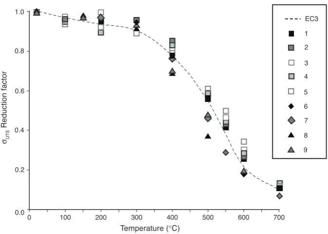
A number of bolt assembly tests have previously been carried out at elevated temperatures under steady-state conditions, in order to evaluate and compare the performance of different bolt assemblies in fire [5, 13-15]. These have been on assemblies of different geometrical tolerances, diameters, steel grades, forming methods (hot and cold) and finishes, as detailed in Table 1. The test methods employed by the different authors, and their resulting ultimate tensile capacities and failure modes, are shown in Table 2. Some assemblies failed in a single failure mode, while others failed in a combination of modes.
Table 1. Summary of the processing and geometrical tolerances of bolt assemblies tested at elevated temperatures in previously published work [5, 13-15]
Assembly Bolt Nut
d Property
Author Ref. (mm) Tolerance Code Grade Formed* Finish Code Class Formed* Finish
1 20 8g7H 4190 8.8 CF SC 4190 8 HF SC
2 20 8g7H 4190 8.8 CF SC 4190 8 CF G
Kirby [5] 3 20 8g7H 4190 8.8 CF SC 4190 8 HF SC
4 20 8g7H 4190 8.8 CF SC 4190 8 CF G
5 20 8g7H 4190 8.8 HF SC 4190 8 HF SC
González [13,14] 6 16 6g6AZ 14399-4 10.9 CF G 14399-4 10 - G 7 16 6g6AZ 14399-4 10.9 CF G 14399-4 10 - G
Hu [15] 8 20 - 4190 8.8 - - - 10 -
-9 20 - ISO 4014 8.8 - - - 10 -
-*Where CF =cold formed, HF =hot formed, SC =self-colour and G =hot dip galvanised
Table 2. Summary of the ultimate load capacities obtained from steady-state tensile tests at a range of temperatures in previously published work [5, 13-15]
Heating Holding Fu (kN) at Temperature (°C)
Strain rate time Failure Author Ref. rate (min−1) (°C/min) (min) 20 100 150 200 300 400 500 550 600 700 Mode**
1 226 216 - 215 217 178 126 94 59 24 N
2 198 191 - 177 190 168 118 86 54 23 S
[5] 3 0.001-0.003 5-10 15 206 201 - 206 203 168 122 96 62 27 N
4 189 180 - 168 176 158 112 85 54 25 S
5 232 217 - 215 206 183 144 116 80 28 C
6 266 - - 254 252 210 123 78 47 19 C
[13, 14] 7 0.0001-0.005 - 30 264 - - 256 245 203 121 76 50 18 C
[15] 8 0.0001* 2-2.5 15 202 - 198 - 187 140 75 - 39 - N
9 239 - 232 - 225 168 115 - 48 - N
*Assuming a 30mm gauge length
Kirby tested at constant strain-rate of 0.001-0.003min−1up to 5% proof stress before increasing the rate
to 0.01min−1up to rupture [5], while González tested at 0.01min−1up to 2% proof stress, and then to
0.025min−1to rupture [13]. This means that ultimate load capacities obtained in these tests may be
disproportionately high if strain rate was increased before the ultimate load capacity was reached. Test methods and strain-rates were not specified by Hu, therefore, his strain-rate was estimated assuming a gauge length of 30mm, and based on the specified test velocity of 0.003mm/min.
The general trend observed was for necking failures to occur at higher ultimate tensile strengths than stripping failures for Grade 8.8 bolts, while Grade 10.9 bolts failed at higher ultimate load capacities by a combination of thread-stripping, necking and liquid metal embrittlement. Assemblies 6 and 7 were temperature-dependent, so that a combination of necking and thread-stripping occurred up to 420°C, liquid metal embrittlement from 420-650°C, and pure stripping above 650°C. Assembly 5 failed by a combination of necking and thread-stripping at all temperatures, with both failure modes occurring at similar ultimate load capacities.
The ultimate load capacities recorded at elevated temperature have been normalised with respect to ambient temperature, and compared to the strength reduction factors given in Eurocode 3 (Figure 1). The Eurocodes suggest reduction factors less severe than those calculated from published ultimate load capacities (or those taken from published graphs) most significantly at temperatures greater than 300°C.
3. EXPERIMENTAL METHODS
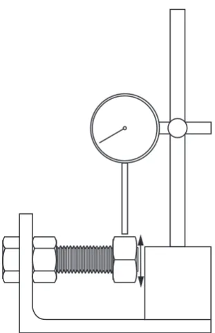
Uniaxial tensile testing was carried out on turned-down bolts as well as bolt assemblies, to determine material behaviour in the bolt across a range of temperatures and strain-rates. Reducing the cross-sectional area of the bolt shank allowed thread deformation effects to be removed. An Instron test machine capable of applying tensile forces up to 1000kN was used with grips originally made for the bolt assembly testing carried out by Hu [15]. These grips have central holes which can accommodate an M20 bolt. For a bolt assembly the bolt passes through both holes and a nut is secured to the end of the bolt shank. The top grip travelled at a constant velocity while the bottom grip held the bolt head stationary. The same set-up was used for turned-down bolts; however, for these tests, the specimen was screwed into two internally-threaded extenders, held in place between the two grips. The test setup and turned-down bolt geometry are shown in Figure 2.
1.0 0.8 0.6 0.4 0.2 0.0
0 100
σUTS
Reduction factor
200 300 400
Temperature (°C)
[image:4.595.137.474.109.349.2]500 600 700 9 8 7 6 5 4 3 2 1 EC3
A large wrap-around convection furnace was used to heat the samples and hold them at constant temperature during testing. Heating times to specimen temperatures of 550-700°C were of the order of 3-6 hours, which meant that thermal gradients were within 1°C at temperatures greater than 550°C. In order to determine where to place the thermocouples, and to measure thermal gradients within the test piece, an unloaded specimen was heated until the furnace reached 700°C. The results are shown in Figure 3 for five thermocouple locations. As a result of these tests it was decided that temperature would be measured from a thermocouple in the bottom shoulder of the specimen, where it could remain
R6 (b)
(a)
R3.5
20 35
Figure 2. (a) Apparatus used for turned-down bolt tests and (b) turned-down bolt geometry.
700 600 500 400 300 200 100 0
T
e
mperature (
°
C)
0 2000 4000 6000
Time (s)
8000 10000 12000 14000 16000
Fumace 5 4 3 2 1
1
[image:5.595.132.453.106.307.2]2 3 4 5
[image:5.595.132.448.374.585.2]stationary throughout the test without affecting the material within the gauge length. No holding time was required once the temperature had stabilised, due to the small thermal gradients which existed.
Structural members are typically only stressed within their elastic range; in which case strain is independent of strain-rate. During fire, however, structural members, including bolt assemblies, typically undergo significant plastic deformation which usually occurs at a high rate of strain [16]. It was therefore decided that three strain-rates would be considered, in addition to four temperatures for turned-down bolts and three temperatures for bolt assemblies. Each temperature and strain-rate combination was tested once for turned-down bolt tests, with at least three repeats tested per combination for bolt assemblies.
3.1. Test Temperatures
Test temperatures of 20, 550, 620 and 700°C were chosen due to current guidelines produced by the Association for Specialist Fire Protection (ASFP) in the ‘Yellow Book’ [17] which prescribe 550°C and 620°C as the limiting steel temperatures for columns and beams respectively. Fire protection thicknesses should be specified so that these temperatures are not exceeded in structural members. The highest temperature of 700°C was chosen as the maximum temperature which unprotected connections are likely to reach in fire.
3.2. Strain-rate
A limiting rate of deflection of L2/9000d (mm/min) at the mid-span of a simply supported beam
subjected to an evenly distributed load is prescribed in BS 476-20 [18]. This is approximately equivalent to a maximum strain-rate of 0.0005min−1. This value is conservative, however, in order to
ensure the safety of the fire test procedure. The slowest strain-rate chosen for the study was therefore 0.002min−1, which is comparable to the 0.001-0.003min−1 used by Kirby [5]. The strain-rate was
maintained up to rupture, unlike the previous material tests carried out by Kirby [5] and González [14] who respectively increased their strain-rates once the stress level was above the 5% and 2% proof stress. Since the flow behaviour is known to be strain-rate dependent, it was decided that a constant rate would provide more accurate ultimate tensile strength and total strain data. Two faster strain-rates were also chosen, since the strain-rate increases during heavy plastic deformation.
Testing was carried out at a constant velocity, where velocity =gauge length/engineering strain-rate, based on a gauge length of 20mm for turned-down bolts and 62mm for bolt assemblies.
3.3. Thread Tolerance Measurement
Since the tolerance between the nut and bolt threads is thought to influence the failure mode, a simple test was carried out prior to testing each assembly, in order to determine the minimum clearance between the nut and bolt threads (Figure 4). Each bolt specimen was slotted through a hole in a right-angle steel section and a nut was then tightened mechanically, using an impact driver, against the steel section so that the bolt was firmly held in place. The nut to be tested was then tightened by hand to a position approximately one thread pitch (2.5mm) from the end of the bolt shank with a flat face at the top. A dial gauge was attached to the steel section, using a magnetic base to eliminate the displacement of the steel-angle, and the maximum and minimum readings were noted as the nut was moved up and down by hand. The differences between these readings were halved in order to give the thread tolerance for each assembly tested (Table 3).
3.4. Data Acquisition
length were marked with glass beads attached to the surface with fire cement. The silhouettes of these beads were clearly visible against the back of the furnace. Displacement was calculated for both beads so that the bottom reading could be subtracted from the top to cancel any tripod movement. The gauge length and cross-sectional diameter were measured three times per specimen prior to testing, and an average taken to allow accurate strain and stress calculations.
For the bolt assembly tests, two spacers were machined from stainless steel, and were respectively placed under the bottom surface of the nut and above the bolt head. These spacers had a slot cut from their front sides to allow the threads to be visible at both ends of the bolt shank, for strain calculation in the case of necking failure under tension. The test velocity was calculated based on the 62mm distance between the centres of these two spacers, when less than one bolt thread pitch was visible above the top surface of the nut. However, in the case of thread-stripping failure where deformation occurred outside the gauge length, the displacement and force readings were adequate, and any area of high contrast on the nut and bolt head could be used for the elongation calculation. Elongation was calculated from the images using GeoPIV, a Matlab module normally used in Geotechnical measurement of strains in soil.
3.5. Post-processing
[image:7.595.213.369.107.348.2]At the start of testing, the rate of loading was slow due to initial adjustments of the position of the test piece and the test rig itself. This effect was removed by calculating the gradient between 1/4 and 3/4 of the UTS, extrapolating this gradient backward to zero force and zeroing displacement (Figure 5).
Table 3. Measured thread clearances (in mm) for each bolt assembly tested
T 0.002min−1 0.01min−1 0.02min−1
(°C) a b c d a b c d a b c d
20 0.229 0.000 0.025 0.127 0.254 0.102 0.178 0.025 0.102 0.000 0.152 0.178 550 0.051 0.178 0.025 - 0.025 0.102 0.127 0.279 0.229 0.152 0.000 0.127 700 0.000 0.127 0.152 - 0.178 0.152 0.000 0.000 0.178 0.254 0.152
[image:7.595.85.498.415.476.2]4. RESULTS
4.1. Turned-down Bolt Testing
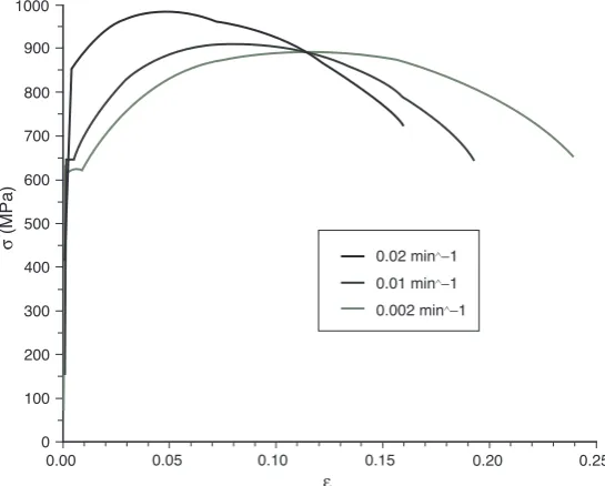
The first three tests were performed at ambient temperature, at all three strain-rates, and the resulting stress-strain curves are shown in Figure 6. In these curves, and in subsequent results, the terms stress and strain refer to true stress σ = s(1 + e)and logarithmic strain ε = ln(1 + e) where e =engineering strain (ΔL/L) and s =engineering stress (F/A).
Displacement Force
Fu 3/4Fu
[image:8.595.180.426.112.306.2]1/4Fu
Figure 5. Removal of initial adjustments upon loading.
1000 900 800 700 600 500 400 300 200 100 0
σ
(MPa)
0.00 0.05 0.10 0.15 0.20 0.25
ε
0.02 min∧−
1 0.01 min∧
−1
0.002 min∧−1
Figure 6. Ambient-temperature results for three specimens tested at 0.02, 0.01 and 0.002min−1
[image:8.595.168.441.462.681.2]The nominal tensile strength prescribed in ISO 898-1 of 800MPa is shown in Figure 6 by a dotted line, and it can be seen that all three data sets exceed this value. Typically strength is a function of deformation rate, with higher strain-rates producing higher strength and reduced ductility. Although this effect is seen in Figure 6, the shapes of the curves are very different from one another. The fastest strain-rate produced the smooth transition from elastic to plastic behaviour which is characteristic of a martensitic microstructure, while the medium and slowest rates produced a yield plateau at a significantly lower yield point, characteristic of pearlite and bainite microstructures [19]. This is surprising, as ISO 898-1 specifies that quenched and tempered M20 Grade 8.8 bolts should contain at least 90% tempered martensite at their centres. Since all three bolts were taken from the same batch, they can be assumed to have similar chemical compositions, and the variations in microstructure are therefore attributable to differences in cooling rates during heat treatment. A faster cooling rate leads to transformation from austenite (present at temperatures above around 730°C) to a harder, more brittle, martensite phase, while slower cooling allows for the diffusion of carbon atoms and transformation to pearlite and/or bainite. A transverse section was cut through the threaded section of each specimen, and the average of fourteen hardness readings across each cross-section was calculated to confirm the presence of different microstructures. The average values for the 0.02, 0.01 and 0.002min−1rates were
313.1, 262.4 and 268.4HV respectively. However the lowest readings obtained for the two slower strain-rates fell below the minimum limit of 255HV given by ISO 898-1.
In order to ensure consistent results and to provide worst-case mechanical properties it was decided to repeat these three tests. The subsequent three specimens were machined from bolts for which the centre of the underside of the bolt head had Vickers Hardness values of 250.1, 241.8, and 247.1HV, which are lower than the specified minimum and indicated a non-martensitic microstructure. The results of these tests were far more consistent, with all three specimens exhibiting a yield plateau at between 600-650MPa (Figure 7(a)). At ambient temperature the effect of strain-rate is negligible for those used in this research; however, at elevated temperatures both strength and ductility were observed to be strain-rate dependent, most significantly so at 550°C (Figure 7(b)).
The elevated-temperature ultimate tensile strength values were normalised with respect to the ambient-temperature test results for each strain-rate. Results can be seen from Figure 8 to be well below the bolt strength reduction factors prescribed in Eurocode 3, most markedly so for the slowest strain rate. This may be due to the slow heating and long test times in this study allowing greater recovery of the bolt material than was possible in Kirby’s tests, which were heated at 5-10°C/min with the strain-rate being increased to 0.01min−1to rupture beyond 5% proof stress. This may also be due to difference
1000
800
600
400
200
0
250
200
150
100
50
0
250
200
150
100
50
0
250
200
150
100
50
0
0.00 0.05 0.10 0.15 0.20 0.25
0.00 0.10 0.20 0.30 0.40 0.50 0.60
0.00 0.10 0.20 0.30 0.40 0.50 0.60
0.00 0.10 0.20 0.30 0.40 0.50 0.60 0.02min∧−1
0.01min∧−1
0.002min∧−1
σ
(MP
a
)
σ
(MP
a
)
σ
(MP
a)
σ
(MP
a)
ε
ε
ε
ε (a)
(b)
(c)
[image:10.595.208.403.114.666.2](d)
4.2. Bolt Assembly Tests
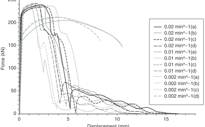
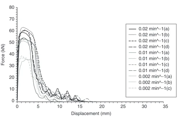
At ambient temperature both failure modes were observed (Figure 9). While the majority of these tests resulted in thread stripping, three failed due to necking of the bolt shank and produced dissimilar force-displacement curves. In previous literature necking failures are reported as tending to occur at loads greater than or equivalent to those for thread-stripping (Table 2). It was surprising, therefore, to see that necking occurred at significantly lower loads in this study (Figure 9). For those assemblies which failed through thread-stripping, there was little strain-rate effect on either the ultimate tensile force or total elongation. This behaviour appeared to be a result of the same microstructural variations observed in Figure 6, with some results producing significantly lower values of strength than expected. Vickers hardness testing was carried out on the undersides of all of the bolt heads, and the averages taken from
1.0
0.9
0.8
0.7
0.6
0.5
0.4
0.3
0.2
0.1
0.0
0 100 200 300 400 500 600 700
0.02min^−1 0.01min^−1 0.002min^−1 EN 1993−1−2 σUTS
Reduction
factor
[image:11.595.124.457.110.310.2]Temperature(°C)
Figure 8. Ultimate tensile strength reduction factors for turned-down bolt tests at 0.002, 0.01 and 0.02 min−1.
250
200
150
100
50
0
0 5 10 15
Displacement (mm)
F
orce (kN)
[image:11.595.127.464.502.710.2]0.02 min^−1(a) 0.02 min^−1(b) 0.02 min^−1(c) 0.02 min^−1(d) 0.01 min^−1(a) 0.01 min^−1(b) 0.01 min^−1(c) 0.01 min^−1(d) 0.002 min^−1(a) 0.002 min^−1(b) 0.002 min^−1(c) 0.002 min^−1(d)
the three readings taken at the bolt centres. The three bolts which failed due to necking produced the lowest readings, of 245.7, 249.9 and 248.3HV for 0.01a, 0.002b and 0.002d respectively, all of which fell below the minimum specified in ISO 898-1, and were comparable to the values measured previously for bolts containing pearlitic and/ or bainitic microstructures. From these observations it is clear that, for those assemblies which contained soft, ductile material, necking was the more likely failure mechanism. Those which contained hard, brittle material were more likely to fail through thread-stripping at higher loads.
Despite the existence of material-dependent failure modes at ambient temperature, all ultimate load capacities were greater than the specified minimum of 203kN, prescribed in ISO 898-1, and at ambient temperature ductility is less important than strength in standard applications, due to the very small beam deflections which are permissible. The ultimate load capacities of those assemblies which failed through thread-stripping were in the region 230-242kN with an average of 236kN, and are significantly higher than any of the load capacities obtained, either through necking or thread-stripping, by Kirby (Table 2).
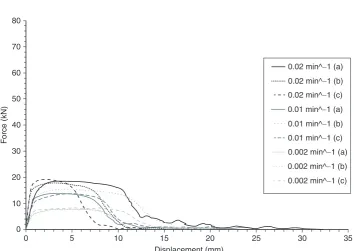
At elevated temperatures ductility becomes far more critical in bolt assemblies which must continue to transfer loads effectively from beams to columns during thermal expansion and subsequent sagging of beams during the growth of a fire. The results of elevated-temperature testing show again that the effect of strain-rate is most pronounced at elevated temperatures, with higher strain-rates producing higher ultimate load capacities in all cases. Ductility was not affected by strain-rate, however, because all assemblies failed through thread-stripping at approximately 5mm extension at 550°C (Figure 10) and 7.5-10mm for 700°C (Figure 11). In these tests, temperatures far exceeded the tempering temperature used during heat treatment, and therefore any variations in microstructure at ambient temperature become less significant after further tempering to 550 or 700°C. The softening of the bulk material seems to have been outweighed by the softening of the threads and subsequent increase in thread deformation. Alternatively, since all bolts were galvanised, there is a marked increase in effective thread clearance above the melting point of the zinc coating. The thickness of the zinc layer should be less than 98µm [20], but this gives a significant increase in clearance compared with the measured clearances in Table 3.
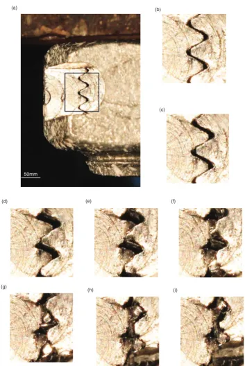
In order to investigate the mechanism of thread-stripping a section was milled out of a nut and bolt to reveal the thread interface (Figure 12(a)). This was then tested under displacement control at ambient temperature, at the same velocity used for the bolt assemblies tested at 0.02min−1. In this
case, the nut was positioned below the bottom of the lower grip and the bolt head above the upper
80
70
60
50
40
30
20
10
0
0 5 10 15 20 25 30 35
Displacement (mm)
F
orce (kN)
[image:12.595.156.464.105.308.2]0.02 min^−1(a) 0.02 min^−1(b) 0.02 min^−1(c) 0.02 min^−1(d) 0.01 min^−1(a) 0.01 min^−1(b) 0.01 min^−1(c) 0.01 min^−1(d) 0.002 min^−1(a) 0.002 min^−1(b) 0.002 min^−1(c)
80
70
60
50
40
30
20
10
0
0 5
F
orce (kN)
10 15 20
Displacement (mm)
25 30
0.02 min^−1 (a)
0.02 min^−1 (b)
0.02 min^−1 (c)
0.01 min^−1 (a)
0.01 min^−1 (b)
0.01 min^−1 (c)
0.002 min^−1 (a)
0.002 min^−1 (b)
0.002 min^−1 (c)
[image:13.595.114.469.97.348.2]35
Figure 11. Results of tensile tests on bolt assemblies at 700°C and three strain-rates.
grip, so that the nut remained stationary. The thread deformations observed explain the peaks which follow the sudden initial drop in load capacity. At the start of loading, the threads make contact (Figure 12(b-c)), and begin to plastically deform and work harden (Figure 12(d-e)). Work hardening relates to the increase in strength caused by an increase in both dislocation density and dislocation interactions during plastic deformation, and the rate of work hardening is most rapid at ambient temperature. The effect of work hardening can be clearly seen in Figure 9, as the slope between yield and ultimate tensile capacity. Within this region of the graph dislocations interact with one another, and other defects in the crystal lattice which impedes further dislocation motion. During plastic deformation, the number of dislocations also multiplies, leading to a greater number of dislocation interactions and increased strengthening. At the onset of thread-stripping, sufficient plastic deformation has occurred for the threads to slide over each other (Figure 12(f-g)). All of the threads which were previously engaged are now heavily deformed, and therefore, the force drops abruptly. Material which has sheared from a thread tip is then pushed up against the flank of the next thread, where plastic deformation and work hardening leads to a slight increase in force (Figure 12(h-i)). As any thread moves over the second adjacent thread, there is another drop in force; these fluctuations in force continue, with the force reducing slightly each time until the nut has completely pulled off the bolt shank.
Figure 12. (a) Specimen tested with section milled to reveal thread interface and (b-i) images taken at different stages of the thread-stripping process.
(c) (b)
(d) (e) (f)
(g)
(h) (i)
(a)
[image:14.595.128.482.106.635.2]5. DISCUSSION
This research has highlighted the importance of tight controls during the manufacture and heat treatment of the components of bolt assemblies in ensuring consistent microstructural properties within the same batch. The failure mode, in the case of this batch of bolts, depends on the microstructure at ambient temperature, with tempered martensite leading to thread-stripping, and bainite and pearlite leading to necking at significantly lower force levels. To ensure transformation to martensite during heat treatment, all bolts in a batch must be quenched rapidly. Since all bolts tested in this study were from a single batch it is likely that those containing weaker microstructures were at the centre of the batch during quenching, and cooled less rapidly due to the temperatures of the bolts surrounding them. Although different microstructures were present, the average hardness values and tensile strengths of three turned-down bolt specimens containing different microstructures were above their specified minima. Therefore, a more stringent testing procedure may be required to ensure the correct microstructure. In order to ensure necking failure of assemblies containing tempered martensite a higher tempering temperature or a longer tempering time would improve ductility at the expense of strength.
In bolt assembly tests only thread-stripping failure was observed at elevated temperatures. One possible reason for this is that zinc has a low melting point, therefore, the effective clearance between threads at 550°C and 700°C is significantly greater than at ambient temperature. Failure mode and strength, however, have been found to have no correlation with clearance in this study.
6. CONCLUSION
At ambient temperature the failure mode of bolt assemblies is dependent on the microstructure. However at elevated temperatures, when ductility is more critical, all assemblies failed through thread-stripping. Thread clearance was not found to influence the failure mode or ultimate capacity in this case; further research is clearly required to determine why all assemblies failed in this way. The results of testing carried out on turned-down bolts has provided accurate material data which will be used in a finite element model to attempt to improve understanding of this. Such a finite element model will
250
200
150
100
50
0
0 0.05
FUTS
(kN)
0.1
Thread clearance (mm)
0.15 0.2 0.25 0.3
20 0.02 min-1
20 0.01 min-1
20 0.002 min-1
550 0.02 min-1
550 0.01 min-1
550 0.002 min-1
700 0.02 min-1
700 0.01 min-1
[image:15.595.114.470.106.337.2]700 0.002 min-1
allow the influence of effects which cannot be tested mechanically to be investigated such as; the effects of the number of threads in contact, relative thread strengths, and thread tolerance, in addition to temperature and strain-rate.
ACKNOWLEDGEMENTS
This research was funded by the Engineering and Physical Sciences Research Council (EPSRC) through the Advanced Metallic Systems Centre for Doctoral Training (CDT).
REFERENCES
[1] BSEN15048-1, Non-preloaded structural bolting assemblies - Part 1: General requirements.
British Standards Institution, 2007.
[2] Moore, D., Private Communication, BCSA, 2010: Sheffield.
[3] BSENISO898-1, Mechanical properties of fasteners made of carbon steel and alloy steel - Part 1: Bolts, screws and studs with specified property classes - Coarse thread and fine pitch thread (ISO 898-1: 2013). British Standards Institution, 2013.
[4] BSEN1993-1-2, Design of steel structures, Part 1-2: General rules - Structural fire design. British Standards Institution, 2005.
[5] Kirby, B. R., The Behaviour of High-Strength Grade 8.8 Bolts in Fire.Journal of Constructional Steel Research, 1995. 33(1–2): p. 3–38.
[6] Kirby, B. R., The Behaviour of High Strength 8.8 Bolts in Fire, British Steel Technical Lab report, Swinden Laboratories, 1992.
[7] BS4190, Specification for ISO metric black hexagon bolts, screws and nuts. British Standards Institution, 1967.
[8] BSISO965-5, ISO general purpose metric screw threads - Tolerances - Part 5: Limits of sizes for internal screw threads to mate with hot-dip galvanized external screw threads with maximum size of tolerance position h before galvanizing. British Standards Institution, 1998.
[9] BSENISO4032, Hexagon regular nuts (style 1) - Product grades A and B. British Standards Institution, 2012.
[10] BSENISO4017, Hexagon head screws - Product grades A and B. British Standards Institution, 2011.
[11] BSENISO4014, Hexagon head bolts - Product grades A and B (ISO 4014:2011). British Standards Institution, 2011.
[12] Alexander, E. M. Analysis and Design of Threaded Assemblies. International Automotive Engineering Congress and Exposition. 1977, Ref. No 770420. Detroit.
[13] Gonzalez, F. and Lange, J. Behaviour of Galvanized High Strength Grade 10.9 Bolts under Fire Conditions. Sixth International Conference Structure in Fire (SiF ‘10). 2010. Michigan State University.
[14] Gonzalez, F., Untersuchungen zum Material- und Tragverhalten von Schrauben der Festigkeitsklasse 10.9 wahrend und nach einem Brand, Veroffentlichung des Institutes fur Stahlbau und Werkstoffmechanik 2011, Technischen Universitat Darmstadt: Darmstadt.
[15] Hu, Y., Davison, J. B., Burgess, I. W., and Plank, R. J. Comparative study of the behaviour of BS 4190 and BS EN ISO 4014 bolts in fire. The 3rd International Conference on Steel and Composite Structures. 2007. Manchester.
[16] Zener, C. and Hollomon, J. H., Effect of Strain Rate Upon Plastic Flow of Steel. Journal of Applied Physics, 1944. 15(1): p. 22–32.
[17] ASFP, Yellow Book: Fire Protection for Structural Steel in Buildings, 4th Edition, 2010. [18] BS476-20, Fire tests on building materials and structures - Part 20: Method for determination of the
[19] Dieter, G. E., Mechanical Metallurgy. SI Metric Edition 1988: McGraw-Hill.