UNIVERSITI TEKNIKAL MALAYSIA MELAKA
NO LOAD LOSS CALCULATION OF 90MVA 132/33kV POWER
TRANSFORMER
This report is submitted in accordance with the requirement of Universiti Teknikal Malaysia Melaka (UTeM) for
Bachelor‟s Degree of Electrical Engineering Technology (Industrial Power) with Honours
by
ANDDY CHIA KOK LIK B071210135
920331-10-5133
UNIVERSITI TEKNIKAL MALAYSIA MELAKA
BORANG PENGESAHAN STATUS LAPORAN PROJEK SARJANA MUDA
TAJUK: No Load Loss Calculation of 90MVA 132/33kV Power Transformer
SESI PENGAJIAN: 2015/16 Semester 2
Saya ANDDY CHIA KOK LIK
mengaku membenarkan Laporan PSM ini disimpan di Perpustakaan Universiti Teknikal Malaysia Melaka (UTeM) dengan syarat-syarat kegunaan seperti berikut:
1. Laporan PSM adalah hak milik Universiti Teknikal Malaysia Melaka dan penulis. 2. Perpustakaan Universiti Teknikal Malaysia Melaka dibenarkan membuat salinan
untuk tujuan pengajian sahaja dengan izin penulis.
3. Perpustakaan dibenarkan membuat salinan laporan PSM ini sebagai bahan pertukaran antara institusi pengajian tinggi.
4. **Sila tandakan ( )
SULIT
TERHAD
TIDAK TERHAD
(Mengandungi maklumat yang berdarjah keselamatan
atau kepentingan Malaysia sebagaimana yang termaktub
dalam AKTA RAHSIA RASMI 1972)
(Mengandungi maklumat TERHAD yang telah ditentukan
oleh organisasi/badan di mana penyelidikan dijalankan)
Alamat Tetap:
NO11, JALAN 7, TAMAN HIEW PIOW 43500 SMENYIH,
SELANGOR DARUL EHSAN
Tarikh: 1 December 2015__________
Disahkan oleh:
Cop Rasmi:
Tarikh: _______________________
DECLARATION
I hereby, declare that this thesis entitled “No Load Loss Calculation of 90MVA 132/33kV Power Transformer” is the result of my own research except as cited in references.
Signature : ………
APPROVAL
This report is submitted to the Faculty of Engineering Technology of UTeM as one of the requirements for the award of Bachelor‟s Degree of Electrical Engineering Technology (Industrial Power) with Honours. The following are the members of supervisory committee:
iv
ABSTRACT
v
ABSTRAK
vi
DEDICATIONS
vii
ACKNOWLEDGEMENT
First and foremost, I would like to thank my project supervisor Mr Zulkifli bin Ibrahim and Mdm. Halyani binti Mohd Yassim who trusted in me and continuously supporting me in every aspect while writing of this report. Without their guidance and dedicated involvement in every step throughout the process, this paper will not be accomplished. I have many people to thanks for listening and having to tolerate with me over past three years. I cannot begin to express my gratitude for their friendship.
viii
TABLE OF CONTENTS
DECLARATION ... i
APPROVAL ... iii
ABSTRACT ... iv
ABSTRAK ... v
DEDICATIONS ... vi
ACKNOWLEDGEMENT ... vii
TABLE OF CONTENTS ... viii
LIST OF TABLES ... xi
LIST OF FIGURES ... xii
CHAPTER 1: INTRODUCTION ... 1
1.1 Introduction ... 1
1.2 Problem Statement ... 2
1.3 Objectives ... 3
1.4 Working Scope ... 3
CHAPTER 2: LITERATURE REVIEW ... 4
2.1 Introduction ... 4
2.2 Power Transformer ... 4
2.3 Core ... 6
2.3.1 Core Construction ... 7
2.3.2 Core Lamination ... 7
2.3.3 Core Material ... 8
2.3.4 Core Type ... 10
2.4 Core Losses ... 11
2.4.1 B-H Curve ... 11
2.4.2 Hysteresis ... 12
ix
2.4.4 Eddy Current ... 14
2.5 Software ... 15
2.5.1 FEM and FEA ... 16
2.5.2 Ansys Maxwell ... 16
CHAPTER 3: METHODOLOGY ... 18
3.1 Introduction ... 18
3.2 1st Milestone ... 20
3.3 2nd Milestone ... 21
3.3.1 Construction Core ... 23
3.3.2 Assign Parameter ... 23
3.3.3 Create Report ... 25
3.3.4 Evaluation and Comparison of Result ... 25
3.4 3rd Milestone ... 26
3.5 4th Milestone ... 27
CHAPTER 4: RESULTS AND DISCUSSION ... 28
4.1 Introduction ... 28
4.2 Expected Result ... 28
4.3 Transformer Design... 28
4.4 Low Voltage Winding and Core Analysis ... 31
4.4.1 Stop Time and Time Step ... 33
4.4.2 Current ... 34
4.4.3 Input Voltage ... 35
4.4.4 Core Loss ... 36
4.4.5 Core Mass ... 36
4.4.6 B-H Curve and Plot ... 37
4.4.7 Mesh ... 39
x
4.6 Core Improvement... 41
4.6.1 Core Height ... 41
4.6.2 Core Loss at Different Height ... 42
4.6.3 Current and Input Voltage ... 43
4.7 Limitation ... 45
CHAPTER 5: CONCLUSION AND RECOMMENDATIONS ... 46
5.1 Introduction ... 46
5.2 Conclusion ... 46
5.3 Recommendation and Future Work ... 46
REFERENCES ... 48
xi
LIST OF TABLES
Table 4.1: Parameter for the transformer core ... 31
Table 4.2: Parameter for the transformer low voltage winding ... 32
Table 4.3: Time steps for the simulation ... 34
Table 4.4: Value of B and H ... 38
Table 4.5: The mesh statistics of the core and windings ... 40
Table 4.6: Core loss at different distance between yokes ... 43
xii
LIST OF FIGURES
Figure 2.1: Power transformer rating of 40MVA is under maintenance ... 6
Figure 2.2: Number of core laminations against transformer rating ... 8
Figure 2.3: Different type crystalline structure ... 9
Figure 2.4: Type of core in power transformer ... 10
Figure 2.5: The B-H curve for ferromagnetic material ... 12
Figure 2.6: Hysteresis curve of ferromagnetic material ... 13
Figure 2.7: Individual lamination sheet; local coordinate system (α, ); parallel and perpendicular magnetic field strength and corresponding eddy current distributions and ... 15
Figure 2.8: The model of transformer is designed by using FEM software ... 16
Figure 2.9: Mesh map of coils in high frequency ... 17
Figure 3.1: The flowchart of the milestone for the project ... 18
Figure 3.2: The flowchart of the project ... 19
Figure 3.3: Flowchart for 1st milestone ... 21
Figure 3.4: Flowchart for 2nd milestone ... 22
Figure 3.5: Designation and analyzation of core losses by using ANSYS Maxwell . 22 Figure 3.6: Flowchart for constructing core ... 23
Figure 3.7: Flowchart for assigned parameter ... 24
Figure 3.8: Flowchart for report creation ... 25
Figure 3.9: Flowchart for 3rd milestone ... 26
Figure 4.1: Construction of core and windings using ANSYS ... 29
Figure 4.2: Parameter of the windings ... 30
Figure 4.3: Dimension of core in 2D drawing ... 30
Figure 4.4: Low voltage windings and core ... 32
Figure 4.5: Start time, stop time and time step for simulation ... 33
Figure 4.6: Current of winding1, winding 2 and winding 3 ... 35
Figure 4.7: Input voltage into winding 1, winding 2 and winding 3 ... 35
Figure 4.8: Core loss graph ... 36
Figure 4.9: Mass density of the core ... 37
Figure 4.10: B-H loop ... 38
xiii
Figure 4.12: Meshing of the core... 39
Figure 4.13: Distance between yoke in a core ... 42
Figure 4.14: Distance between yokes versus core losses graph ... 43
Figure 4.15: Graph of current at different distance between yokes ... 44
xiv LIST OF ABBREVATIONS, SYMBOLS AND NOMENCLATURES
FEM = Finite Element Method FEA = Finite Element Analysis CGRO = Cold Rolled Grained-Oriented
MVA = Mega Volt Ampere
kVA = Kilo Volt Ampere
B = Magnetic Flux Density
H = Magnetization Force
EMF = Electromotive Force
3D = 3 Dimensional
1
CHAPTER 1
INTRODUCTION
1.1 Introduction
Transformer is an omnipresent device which can be categorised into step-up as well as step-down transformer. Step-up transformer is where the transformer increases the voltage from the primary winding to secondary winding where the primary winding turns are lesser than secondary winding turns. Once the voltage being stepped up eventually the current will decreases and this results the amount of eddy current loss is lowered. As a result, the transformer can perform better in transferring the power in long distance due to its higher transmission efficiency. Conversely, the step-down transformer was designed oppositely from the step-up transformer.
According to Olivares-Galván et al. (2009), the preeminent losses of the transformer can be categorized into 3 types which are tank losses due to high-current bushings, losses in transformer core joints and stray losses in the transformer tank. Those aforementioned losses might cause degradation of the transformer and lower its efficiency. In this project, losses in transformer core were studied.
2 Generally, there are two types of core losses includes hysteresis and eddy current losses. Hysteresis can be defined as the time-based dependence of a system‟s output on the current and past input. Meanwhile eddy currents are circular electric currents that being induced within conductor by altering the magnetic field in conductor. Both types of these losses will be explained in chapter 2.
In this project, Finite Element Method (ANSYS MAXWELL) was used to collect and plot the data that are related to the core losses as well as to design and analyse a 2D and 3D transformer. The results obtained were studied in order to improve the efficiency of the transformer by minimizing the amount of losses.
1.2 Problem Statement
3
1.3 Objectives
i. To obtain data of losses and magnetic plot of transformer using FEM
ii. To identify method to minimize losses in the transformer core
1.4 Working Scope
In order to achieve the stated objectives, several work scopes had been identified. The work scopes are listed as below:
i. Translate the design parameter or dimension into FEM simulation model
ii. Calculate no-load losses
iii. Plot the magnetic field (B) of the core
iv. Compare the simulated result with actual result
4
CHAPTER 2
LITERATURE REVIEW
2.1 Introduction
This chapter focuses on power transformer, transformer core, core losses, and Finite Element Method. Power transformer is used to step up or step down voltage in transmission system and distribution system where the working principle of power transformer is similar to normal transformer. Transformer core which usually experience loss is an important element to be studied in order to ensure the efficiency of the power transformer is maintained. Besides, Finite Element Method was used throughout this project.
2.2 Power Transformer
Power transformer is defined as the transformer which rated 500kVA and above. Generally, power transformer is installed in a transmission system or in a distribution system. This type of transformer can be further categorised into 3 groups which are small, medium and large power transformer. Small power transformer has the range between 500kVA until 7500kVA meanwhile medium power transformer has the range between 7500kVA and 100MVA. As for the large power transformer, its rate is above 100MVA. In addition, the specification of the power transformer is selected according to its respective application. Generally, power transformer in a transmission system is responsible to step up the voltage whereas it is used to step down the voltage in a distribution system.
5 step up transformer has more windings in the secondary coil compared to primary coil whereas for a step down transformer is vice versa.
Besides that, transformer oil has two vital functions in power transformer where it is responsible to provide insulation as well as to cool the core and windings in the same time. Generally, the oil used in the power transformer is in the form of hydrocarbon mineral oil. The purpose of tap changer in the transformer is to vary the output voltage according to the condition of the load. The tap changer will switch in order to provide a higher voltage during the peak load. However, in a sophisticated transformer, the tap changer is an automatic type.
The function of the conservator is to store the transformer oil and it is located above the transformer. The oil level is approximately in the middle of the tank which allows the expansion and contraction of oil. Transformer breather is a container which filled with silica gel. It absorbs the moisture from the air that enters into the tank. This is to prevent the moisture to cause fault towards the transformer. Cooling tubes is one of the important parts in the transformer because it functions to cool the transformer oil. Certain cooling tubes are installed with pump in order to circulate the oil.
6 Figure 2.1: Power transformer rating of 40MVA is under maintenance
Source: Purwadi et al. (2011)
2.3 Core
Core is used to hold the windings in the transformer besides than giving a low reluctance path to the flow of the magnetic flux. Materials used and geometry of the core are crucial properties in order to optimize the function of the power transformer. The transformer can be inefficient due to poor or inappropriate design even it is made from best materials. According to Marketos et al. (2012), factors such as type of steel used, core geometry and stacking configurations are important in no-load loss calculation in the transformer
7 2.3.1 Core Construction
Core construction is the way of how the core is being build up. Generally, there are two types of construction which are the stacked core construction as well as the wound core construction. The main difference between both constructions is the number of gaps or joints of the core. Wound core has less or no joints in the core. As a result, the carried flux by the core almost uninterrupted by the gaps. In addition, wound core is very common being used in smaller distribution transformer. Besides that, the drawbacks of this wound core is more costly and required certain techniques to do windings. In contrast, the stacked core construction consists of many joints in it which can result a poor magnetic characteristic. Different T-joints configuration in core such 23 degrees, 45 degrees, 60 degrees and 90 degrees affect the efficiency of the transformer core loss as explained by Haidar and Al-Dabbagh (2013). However, this type of construction is predominating in larger transformer.
2.3.2 Core Lamination
8 versatility. The flux in the mentioned type is in the direction of the rolling in all legs of these cores.
Figure 2.2: Number of core laminations against transformer rating Source: Olivares-Galvan, Georgilakis et al.(2013)
2.3.3 Core Material
Materials that are used to build power transformer core must in the form of magnetic material. Few examples of magnetic materials are soft iron, carbonyl iron, ferrite and others. However the mentioned materials are more suitable for small size transformer and electronic transformer but not power transformer. Normally, power transformer uses Cold Rolled Grain-oriented with steels or amorphous metal to build its core.
Iron is not suitable for power transformer because it has low saturation of flux density especially when in high temperature as described by Du et al. (2010). As a result, Cold Rolled Grain-oriented (CRGO) steel or amorphous is used to make the power transformer core. This is because steel is an alloy that comprises of iron and carbon. The CRGO steel is specially processed in order to develop a special grain orientation in the
178 183
217
256
294 294
139 148
165
213 230
261
104 119
148 152
200
170
5 10 15 25 37.5 50
Numbe
r of
laminations
Transformer rating (kVA)
N. of laminations of M2
N. of laminations of M3
9 steel and this CRGO steel also produces certain magnetic properties such as low core loss and higher permeability.
Furthermore, silicon is also another element that can be added to this steel in order to improve its physical properties. Important parameters for the physical properties of silicon steels include resistivity, saturation induction, magneto-crystalline anisotropy, the magnetostriction and the Curie temperature. According to Ashbahani et al. (2011), an efficient and economical electrical transformer needs a high permeability and low core loss and this can be found in silicon alloys which normally consists of 3% of silicon level. Besides, addition of silicon can increase the resistivity and permeability, decrease the hysteresis loss, and virtually eliminated aging.
[image:24.595.302.473.482.646.2]Besides that, an amorphous metal is also known as metallic glass or glassy metal. They are typical alloy of iron with Boron, Silicon and Phosphorus. Amorphous steel is hardened during its metallurgical process. As a result, the amorphous steel has a non-crystalline structure which gives higher resistivity compared to non-crystalline structure. Besides that, the mentioned metal is soft magnetic material which has low coercivity and core loss as well as high permeability. According to Yurekten et al. (2013), the core loss in amorphous oriented core is 25-30% lesser than the CRGO silicon steel type and this can improve the efficiency to the transformer. Thus, CRGO is built with amorphous oriented.
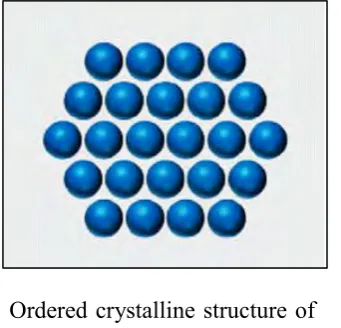
Figure 2.3: Different type crystalline structure Source: Ramanan and Carlen (2012)
Disordered crystalline structure