This is a repository copy of
Method of analysis for 2-D lumped element filter networks
.
White Rose Research Online URL for this paper:
http://eprints.whiterose.ac.uk/88312/
Version: Accepted Version
Proceedings Paper:
Hunter, IC, Rhodes, J, Snyder, RV et al. (1 more author) (2015) Method of analysis for 2-D
lumped element filter networks. In: IEEE MTT S International Microwave Symposium
Digest. IEEE MTT S International Microwave Symposium, 17-22 May 2015, Phoenix,
Arizona, USA. Institute of Electrical and Electronics Engineers (IEEE) . ISBN
978-1-4799-8275-2
https://doi.org/10.1109/MWSYM.2015.7166851
[email protected] https://eprints.whiterose.ac.uk/
Reuse
Unless indicated otherwise, fulltext items are protected by copyright with all rights reserved. The copyright exception in section 29 of the Copyright, Designs and Patents Act 1988 allows the making of a single copy solely for the purpose of non-commercial research or private study within the limits of fair dealing. The publisher or other rights-holder may allow further reproduction and re-use of this version - refer to the White Rose Research Online record for this item. Where records identify the publisher as the copyright holder, users can verify any specific terms of use on the publisher’s website.
Takedown
If you consider content in White Rose Research Online to be in breach of UK law, please notify us by
Analysis of Two-Dimensional 2-D Filter Networks
Ian C. Hunter, John D. Rhodes, Meng Meng
Institute of Microwaves and Photonics, School of Electronic and Electrical Engineering, University of
Leeds, Leeds LS2 9JT, UK
Abstract — A method for the analysis of 2-D lumped element filter networks is presented. The method is based on the general
telegrapher’s equations of multi-wire transmission lines. In the discussion of multi-wire line, it supports multi-mode propagations. A 2-D lumped element network is equivalent to a set of sub-networks that are combiner at the input and output. While the combiners are generated according to the eigenvector of the characteristic matrix of the 2-D network, each of the sub-network is a lowpass sub-network that supports a single mode propagation whose propagation constant corresponding to a eigenvalue of the characteristic matrix. This method can be applied to the analysis of metamaterials and can be used for the design of waffle-iron filters.
Index Terms — Metamaterial, Waffle-iron filter
I. INTRODUCTION
The problem of multi-mode propagation in a 2-D network was introduced in [1] as a method of interpreting the origination of negative refraction. The method of analysis is based on the discussion of wave propagation in multi-wire line that is presented in [2]. First, a 2-D lumped element network is derived from the multi-wire line structure and it is shown that it supports multi-mode of propagations [3]. Then method of analysis is given for 2D networks with N by M nodes and it is shown that the network is equivalent to a combination of N sub-networks. Each of the sub-networks is a M degree lowpass network that supports a single mode of propagation. While these single modes are independent of each other, they are combined at the input and output by 2-N port combiners. Finally, the method of analysis is applied to waffle-iron filters as discussed in [4] and [5] and is verified by its EM simulations..
It is thus shown that for a general non-uniform 2D structure that can be modelled by a lumped element network, there are always multiple mode of propagation. Single mode of propagation used in much of the discussion of metamaterial occurs only with a specific arrangement of input voltages or when the inductance matrix is the inverse of the capacitance matrix.
II. MULTIMODE PROPAGATIONS
The method of analysis for 2-D filters begins with the discussion of multi-mode propagation in N-wire line as introduced in [2].
A. The analysis of N-wire line structure
A transverse field component E(z-vt) satisfies the wave equation everywhere in the transverse plane even after the
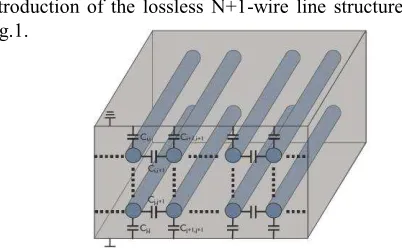
[image:2.612.324.525.147.271.2]introduction of the lossless N+1-wire line structure shown in Fig.1.
Fig. 1. Illustration of the N-wire line with coupling capacitance.
Assuming there is a ground conductor then the voltages on each of the remaining N wires can be calculated from a line integral along any path to each of the conductors producing a unique set of voltages Vr for r=1 to n. Since the E field has the solution E(z-vt) everywhere in the cross sectional plane then each voltage has the same argument and hence the voltage column vector is [V(z-vt)]. Let the current flow on each conductor be described by the vector [I]. The loss of charge on the wires over an incremental length dz is given in (1a) where [C] is the capacitance matrix with the necessary and sufficient conditions on realisability being that [C] is hyperdominant i.e. all off diagonal terms are negative and the sum of all rows and columns are non-negative. In the limit, (1a) is equivalent to (1b).
Q z
C V (1a)
C V zQ
(1b)
Using the definition of current, (1b) is equivalent to the differential equation in (2a) which gives the loss of current along the lines. A new matrix which can be called an inductance matrix [3] which is defined with respect to loss of voltage along the lines as in (2b).
t V C z I
(2a)
t I L z V
(2b)
Eliminating [I] and [V] in (2a) and (2b), we obtain (3) since [V] and [I] have the argument (z-vt).
''
'' ' ' ''
2 2
I L C I
V C L V
Assuming there is a single mode of propagation in the N-wire line metamaterial, (3) is expressed in (4a). For a solution we have (4b).
2 1
'' 0 V C L (4a)
1 21
C
L
(4b)
We can now define characteristic impedance and admittance matrices as in (5).
Y C L Z (5)
For propagation along the z axis of the form e- z, then we have (6).
V 2
LCV2
(6)
In general the propagation constants are the eigenvalues of the equation as in (7a) and (7b).
Z Y2
1 0 (7a)
2 0F (7b)
Thus for a single mode of propagation, [Z] = [Y]-1 apart from a scalar multiplier. In general this is not the case and F is a complex multi-valued function with N solutions for all connected by branch points of the square root variety. The modes must all exist simultaneously with N positive solutions representing forward waves and N negative solutions representing waves travelling in the opposite direction.
B. 3rd order network analysis
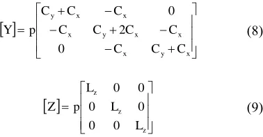
[image:3.612.362.551.54.153.2]Consider the simplest structure where the transverse network is an array of three capacitors to ground with coupling constrained to adjacent capacitors. And the series elements form an array of coupled inductors as in Fig.2. The network in has 3 nodes in the transversal plane and infinity sections cascading along the z direction. The vertical capacitances Cy represent the couplings to ground. The horizontal capacitances Cx represent the couplings between adjacent nodes. The inductance along z direction represents self inductance of the wire. The admittance and impedance matrices of a basic section are given in (8) and (9).
Fig. 2. Circuit model of the metamaterial with 3 transversal nodes.
x y x x x y x x x y C C C C C C C C C C p Y 0 2 0 (8)
z z z L L L p Z 0 0 0 0 0 0 (9)When Cx=1, Cy=2 and Lz=2, The eigenvalues of the characteristic matrix [Y][Z] are 4p2, 6p2 and 10p2 which corresponding to propagating constant of ±2p , ±√6p and
±√10p for the three existing modes. The normalized eigenvectors are given in (10).
6 1 2 1 3 1 6 2 0 3 1 6 1 2 1 3 1 V (10)For sinusoidal wave, the eigenvectors represent the input voltage at the three nodes which will excite the eigenmode with corresponding eigenvalues. The first eigenvector represents equal voltages at the three input nodes. This case is equivalent to an even mode excitation, so that a even mode analysis can be applied as shown in Fig. 3a providing the equivalent circuit with propagation constant of ±2p. The second eigenvector represents a zero voltage at the second node and the equivalent circuit is shown in Fig. 3b. The propagation constant of this mode is ±2p. For the third eigenvector, as in Fig. 3c, the voltage across Cy is V0 and the voltage across Cx is 3V0 which provides an equivalent capacitance of 3Cx. As a result, the propagation constant is
±√10p.
(a)
(b)
[image:3.612.349.559.476.651.2](c)
III. WAFFLE-IRON FILTER
Waffle-iron was invented by S.B. Cohn in 1950s [4] and developed by Leo Young in 1960s [5]. It is a waveguide lowpass filter which has a wide stop band. Due to the effect of cut-off frequency of waveguide, the filter exhibits a bandpass characteristic. The design is developed from ridged waveguide filter and has the advantage of little spurious mode in the stop band.
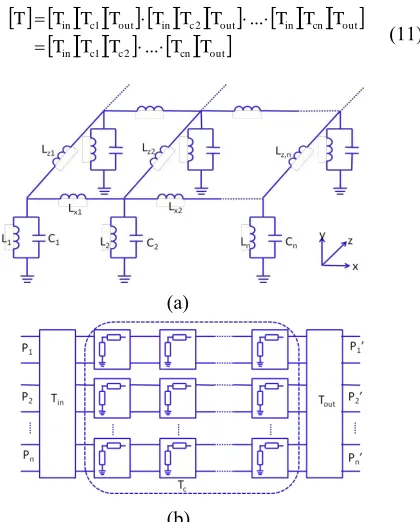
The circuit model of waffle-iron filter is shown in Fig.4a. It consists of bandpass resonators similar to those of combline filters that extend in 2 dimensional. It has N resonators along x-axis connected by inductance Lx and has M blocks along z-axis connected by inductance Lz. When the circuit elements have uniform values, its characteristic matrix [Y][Z] is symmetric. The transfer matrix can be block diagonalized and is equivalent to a network consisting of N branches combined at the input and output by 2N-port combiners. The transfer matrices of the combiners are Tin and Tout as in (11). Because each of the Tci matrix is block diagonalized, each branch supports the propagation of one mode and the equivalent circuit is shown in Fig.4b.
in c c cn outout cn in out c in out c in
T T T T T
T T T T T T T T T T
...
...
2 1
2 1
(11)
(a)
[image:4.612.312.545.261.511.2](b)
Fig. 4. Illustration of the network of 2-D waffle-iron filter (a) and its equivalence (b).
The example is a waffle-iron filter with 5 sections in x direction and 10 sections in z direction. For a five section waffle iron filter with the illustrated configuration, its eigenvectors are listed below and the values of the eigenvectors are independent of the values assigned to the elements of the network. The values of the eigenvector represent to five sinusoidal waves which correspond to the five initial modes of a rectangular waveguide.
V1= -0.1954, -0.5117, -0.6325, -0.5117, -0.1954 V2= -0.3717, -0.6015, 0, 0.6015, 0.3717 V3= -0.5117, -0.1954, 0.6325, -0.1954, -0.5117 V4= -0.6015, 0.3717, 0, -0.3717, 0.6015 V5= 0.4472, -0.4472, 0.4472, -0.4472, 0.4472
When the input voltage is the same as a set of eigenvector, there should be only one corresponding mode propagating in the network. The S21 of these five modes are compared in Fig.5. Each of these five modes has a passband and a different center frequency.
An EM model of a waffle iron filter with five section in the transversal plane and ten sections in the longitudinal plane is simulated in HFSS. There are five propagating mode in this structure. The transfer functions of the first and fifth mode are shown as green lines in figures below. As the five propagating modes have little interaction with each other, the response of the EM simulation is quite similar to that of a circuit model.
Fig. 5. Illustration of the equivalence of 2-D waffle-iron filter.
Fig. 6. Simulated S parameter of the first and fifth mode
VII.CONCLUSION
In this paper, method of analysis is given for the multi-mode propagation in multi-wire lines. 2-D network consisting of lumped elements are studied which shows that this kind of network supports multi-mode of propagation. Waffle-iron filters are examples of these 2-D networks and simulations results are given and compared with circuit analysis.
REFERENCES
[1] I.C.Hunter, A.I.Abunjaileh, J.D.Rhodes, R.V. Snyder, M.Meng,
“Propagation and Negative Refraction”, IEEE Microwave
Magazine, Vol.13, No.5, July/Aug 2012, pp. 58-65.
0 0.5 1 1.5 2 2.5 3
-250 -200 -150 -100 -50 0
Normalized frequency
S2
1
(
d
B
)
Mode 1 Mode 2 Mode 3 Mode 4 Mode 5
1 1.5 2 2.5 3 3.5 4
-180 -160 -140 -120 -100 -80 -60 -40 -20 0
Frequency (GHz)
S2
1
(
d
B
)
[image:4.612.70.280.315.576.2][2] J.O.Scanlan, “Theory of Microwave Coupled Line
Networks”Proc IEEE, Vol. 68, No. 2, Feb.1980 pp.209-232. [3] J.D Rhodes “General Constraints on Propagation Characteristics
of Electromagnetic Waves in Uniform Inhomogeneous
Waveguides” Proc. IEE, Vol.118, No.7, July 1971.
[4] Cohn, S. B., Jones, E. M. T., Shimizu, J. K., Schiffman, B. M.,
and Coale, F. S., ‘Research on design criterialfor microwave filters’, Final report, June 1957, Project 1331, Stanford
Research Institute