Abstract: The network on chip is the key component of the achieving the high performance required by the system designed on the single chip. The mesh and torus topologies have found there places in various system on chips. Still there is an exploration for the better topologies, which can help in reducing the latency of the packet delivered from one core to another core on the chip. In this paper, a new variant of Torus topology has been proposed and the performance of the network is being evaluated on simulator using various synthetic traffics. On comparing the average latency of the cubic torus with other five topologies, it has been observed that the cubic torus has the least latency in comparison to the other existing topologies.
Index Terms: Topology, Network on Chip, Interconnection Networks
I. INTRODUCTION
Network-on-Chips (NoCs) have provided the reliable, fast and energy efficient solution for designing the multi core architecture and executing there application [1]. However there are some challenges while designing the Network on chip base architecture. These challenges can be broadly classified in to classes i) the layout on the chip, that is how the various intellectual properties are place on chip to form a topology and ii) the routing mechanism and flow control mechanism used for communicating the data effectively [2]. The topologies are the base of the every routing algorithm to work, if the topology is unable to support the desired resources required for the particular task then it is not possible to get the performance, as the routing algorithm is only responsible for effective utilization of the underlying network. In the earlier version of systems the 2D NoC were used and contains the several disadvantages like large amount of wire delay that is proportional to the length of wire. The length of wire depends upon the number of nodes are increasing in the row. Second major issue with the 2D NoC is that they have huge amount of heat dissipation[3]. It has studied by the various researchers that the amount of heat dissipated and wire length are greatly reduced in the case of 3D NoC[4–6]. The main advantage of using 3 dimensional topologies is the availability of 3D integrated chip (IC) and combines it with NoC. In 3D IC multiple layers are connected to each other using the miniature links in the third dimension.
Revised Manuscript Received on April 18, 2019.
Akash Punhani, Department of Computer Science and Engineering, Amity University/ ASET, Noida, India
Neetu Faujdar, Department of Computer Science and Engineering, Amity University/ ASET, Noida, India
Sunil Kumar, Department of Computer Science and Engineering, Amity University/ ASET, Noida, India
.
The most popular technique used of vertical connection is, Through-Silicon-Vias (TSVs) is the popular used due to it is highly energy efficient and high provides high throughput [7]. The most popular topologies in the interconnection network are mesh/torus connected. This motivated us to design the topology from the mesh topology which has been involved various super computer configurations like Illiac IV, CM-2, Intel Paragon [8], Seitz’s Cosmic Cube[9, 10]. The performance of the topology is analyzed using the two types of properties in the initial study of the topology the four basic physical properties of the topology used to get the estimate of the performance in comparison to the popular known topologies. The four topological properties that are used in the study are:
1.. Degree: It is the measure of the number of the ports that are used to connect the links. In most of the cases, the bidirectional channels are used in the topologies to make the routing process symmetrical. As bidirectional, channels may be considered of degree 1 or degree 2, for the simplicity in our paper we have considered it as of degree 2. The higher degree of the node implies the complex hardware configuration of the router.
2.Diameter: It is shortest path between the two nodes that are located at the maximum geographical distance in the topology. Large diameter implies that the packet has to spend more time on the communication channel. Therefore, the latency of the network will increase.
3.Bisection width: This describes the number of channel that must be removed from the topology such that the topology gets divides into two sub topologies that are having equal number of nodes but are disconnected from each other. Higher the bisection width the are more alternate path at the time of congestion. Higher bisection width also induces the fault tolerance in the network.
4.Edge length: It is defined as the length of the channels as there are possibility of having long channels just like in torus topologies. Nevertheless, this introduces the non-uniform delays in the network. Another major drawback of long links is that they affects the scalability of the network
Another type of the analysis of the network is based upon the simulation of the network using the simulator and gets the performance measures on the parameters under consideration. The most popular performance measures used for the network analysis are:
1.Throughput: It is the measure of the amount of data received at the destination node.
Design and Evaluation of Cubic Torus
Network-on-Chip Architecture
2.As in the study of mesh like topologies, there are multiple source and destination, so the average of throughput of each destination node is computed to get the average throughput of the topology.
3.Latency: It is the overall time required to move from the source to destination. Again, as we have multiple number of nodes as source and destination, hence the mean value of all the latencies is estimated.
In this paper, we will discuss the details of the popular topologies like mesh, torus and there variants in the section 2. Section 3, presents the cubic torus topology and the various physical properties are discussed. In section 4, the comparison of the cubic torus is done with the five other topologies. Section 5 discusses the future perspective of work.
II. RELATED WORK
Most of the NoCs prefers the mesh topology, due to the facts the topology is simple to design. It has been identified that the topology is based on the tile based architecture[11] which states that the area required on the chip by the mesh architecture is minimum.
A. Mesh Topology
[image:2.595.311.537.100.308.2]The mesh topology is simple topology. The topology is described in the figure 1 below. From the figure, it can be observed that in the mesh topology, there are three types of nodes. The nodes have the degree with in the range of two to four. All the inner nodes are having the degree 4. The outer degree nodes have the degree 3 but the corner nodes have the degree 2. The diameter of the topology is given by the relation 2 × (n-1) for n × n topology. The bisection width of the topology is n-1.
Fig 1. Mesh of 3×3
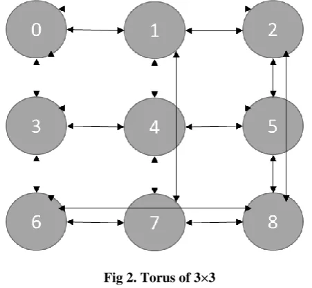
B. Torus Topology
This topology is formed by the adding the toroidal links on the corner nodes horizontally and vertically. The torus topology is described in the figure 2. The degree of each node in the torus topology is four. The main advantage of having the uniform degree and horizontal and vertical links is that it makes the topological symmetrical on the perspective of the routing algorithm. The bisection width of the topology has
[image:2.595.55.259.476.649.2]doubled. The main contain of this topology lies in the point that the edge lengths of the torodial links have increased a lot. This increase in the edge length effects the scalability of the topology.
Fig 2. Torus of 3×3
C. Modified versions of Mesh and Torus Topologies The different modifications of mesh topologies that have been suggested in past by different researchers with the efforts to reduce the diameter and average hop count. The topologies like c2 mesh, Cross Bypass (CBP)-Mesh[12], MDMIN, D-Mesh, X mesh[13], X mesh[14], X torus[15], xx torus[16] all have introduced the diagonal links to the two dimensional mesh with the objective to reduce the average internode distance. The main advantage of studying the average internode distance is that it help in getting the destination using the shortest path and consider the overall performance of the system, instead of focusing the reducing the diameter which will affect the performance of few new nodes in the system. Another idea that have been in the past is to use the evolutionary algorithms for exploring the topologies which have used the average internode distance for the adding the links to the topology.[17]
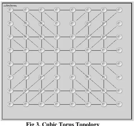
III. CUBIC TORUS TOPOLOGY
Fig 3. Cubic Torus Topology
A. Experimental Setup
[image:3.595.55.281.363.568.2]The cubic torus topology is designed on the OMNET++ [18]Simulator. Test parameters used in the testing of topology are described in Table I. The performance of the topology is tested and compared with the networks like mesh, c2 mesh and DCM topologies[19–23].
TABLE I: Test Bed Parameters Sno Parameter Value
1 Rows 8
2 Columns 8
3 Link
bandwidth
1Gbps
4 Simulation
time
2ms
5 Warm up
time
400us
6 Packet size 1024 bytes 7 Inter packet
arrival delays
(163.84,81.92,54.61, 40.96,32.77,27.31,23.41, 20.48,18.20,16.38, 13.65,11.70,10.24,9. 1,8.19,6.83,
5.85,5.12,4.55,4.09)us
The performance of the cubic torus topology is tested on the four traffic patterns that are stated below:
1.Uniform Random Traffic:
If the data packets are distributed evenly and randomly over the nodes of the topology then this type of traffic is called uniformly distributed traffic.
This can be represented by (1)
n rand
D ()% (1)
In (1) the D represents the Destination Address and n is an integer stating the total number of nodes in the topology.
2.Bit complement traffic:
In bit complement traffic, the source node address is used for the computation of the destination node address. The destination address is computed with the help (2). In (2) the
destination address is represented by D. N represents the total number of nodes in the topology and S is the id of the source node. By id we mean to refer the integer value that represents it position in the tile.
S N
D (2)
3. Neighborhood traffic:
The packets are transferred to the nodes adjacent in the topology. The neighbours can be of either horizontal, vertical or diagonal to the node in the topology. In the current scenario, the diagonal neighbours are considered for the analysis. As we are having m rows and n columns, the (3) represent the formulae, which is used for the computation of the destination address and S is the source address from which the destination address is computed.
% 1
%( )1 m S m n m
n S
D
(3)
4. Tornado traffic:
In this type of traffic, the packets are send to destination that is almost half of the nodes apart from the given node. Again, there are possibilities of the various types of neighbours that are horizontal, vertical, or diagonal relative to the given node. Again, another major problem to this traffic is that addition or subtraction of N/2 to the source address may lead to the generation of the addresses that are out of the range of the node addresses from zero to N-1. Again taking the modulus of the generated address with total number of nodes may help us to generate the traffic in the given address space. The formulation for the packet generation to the destination is given by (4). In (4), n and m represents the number of rows and columns in the topology.
) %( 2 %
2 n m
m m S m n n S
D
(4)
IV. RESULTS AND DISCUSSION
The comparison of the performance of the topology is done with the five other topologies on four different traffic patterns
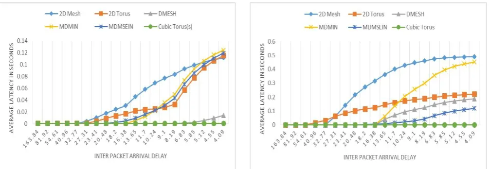
A. Uniform Traffic:
Fig 4. Average latencies of various topologoes on uniform traffic
B. Neighbour Traffic
From the figure 5 it can be observed that the proposed topology is comparable to the DMESH topology. The performance of topology is dominated basically of the diagonal links. The absence of totodial links has reduced the performance of the 2D Mesh topology. As in the study of the topology we have considered the diagonal neighbours in comparison to the horizontal and vertical neighbours.
Fig 5. Average latencies of various topologoes on neighbour traffic
C. Bit Complement
From figure 6 it can be observed MDSEIN topology has performed comparable upto the interpacket arrrival delay of 13.65 μs. However the performance of the Cubic torus is best in comparison to the the other topologies. However at the higher loads the performance of Cubic Torus has dominated in comparison to the performance of MDMSEIN topology.
Fig 6. Average latencies of various topologoes on bit complement traffic
D. Tornado traffic
[image:4.595.303.551.328.500.2]The Average latency of the packet for the cubic torus topology is again better than the existing topologies. However the performance of the DMESH topology is comaprable till the inter packet arrival delay of the 16.38 μs.
Fig 7. Average latencies of various topologoes on tornado traffic
V. CONCLUSION
[image:4.595.46.295.360.543.2]REFERENCES
1. J. Alshraiedeh and A. Kodi, “An adaptive routing algorithm to improve lifetime reliability in NoCs architecture,” in 2016 IEEE International Symposium on Defect and Fault Tolerance in VLSI and Nanotechnology Systems (DFT), 2016, pp. 127–130.
2. A. Benmessaoud Gabis, P. Bomel, and M. Sevaux, “Bi-Objective Cost Function for Adaptive Routing in Network-on-Chip,” IEEE Trans. Multi-Scale Comput. Syst., vol. 7766, no. c, pp. 1–1, 2018.
3. M. Ebrahimi, M. Daneshtalab, P. Liljeberg, J. Plosila, J. Flich, and H. Tenhunen, “Path-Based Partitioning Methods for 3D Networks-on-Chip with Minimal Adaptive Routing,” Comput. IEEE Trans., vol. 63, no. 3, pp. 718–733, 2014.
4. A. Chauhan, A. Punhani, and Nitin, “EMC2Mesh,” in 12th IEEE International Conference Electronics, Energy, Environment, Communication, Computer, Control: (E3-C3), INDICON 2015, 2016. 5. B. S. Feero and P. P. Pande, “Networks-on-Chip in a Three-Dimensional Environment: A Performance Evaluation,” IEEE Trans. Comput., vol. 58, no. 1, pp. 32–45, Jan. 2009.
6. V. F. Pavlidis and E. G. Friedman, “3-D Topologies for Networks-on-Chip,” IEEE Trans. Very Large Scale Integr. Syst., vol. 15, no. 10, pp. 1081–1090, Oct. 2007.
7. M. R. Ansari, A. Q. Ansari, and M. A. Khan, “Design and Evaluation of Binary-Tree Based Scalable 2D and 3D Network-on-Chip Architecture,” Smart Sci., vol. 5, no. 4, pp. 194–198, Oct. 2017. 8. K. Hwang, Advanced computer architecture with parallel
programming. McGraw-Hill, 1993.
9. C. L. Seitz, “The cosmic cube,” Commun. ACM, vol. 28, no. 1, pp. 22–33, Jan. 1985.
10. S. Bataineh, A. Odet‐ Allah, and R. Al‐Omari, “Reliability of mesh and torus topologies in the presence of faults,” Telecommun. Syst., vol. 10, no. 3/4, pp. 389–408, 1998.
11. W. J. Dally and B. Towles, “Route Packets, Not Wires: On-Chip Interconnection Networks,” in Proceedings of the 38th conference on Design automation - DAC ’01, 2001, pp. 684–689.
12. U. A. Gulzari, M. Sajid, S. Anjum, S. Agha, and F. S. Torres, “A New Cross-By-Pass-Torus Architecture Based on CBP-Mesh and Torus Interconnection for On-Chip Communication,” PLoS One, vol. 11, no. 12, p. e0167590, Dec. 2016.
13. X.-J. ZHU, “Xmesh: A Mesh-Like Topology for Network on Chip,” J. Softw., vol. 18, no. 9, p. 2194, 2007.
14. J. J. Kim and H. M. Choi, “XMESH interconnection network for massively parallel computers,” IEE Proc. - Comput. Digit. Tech., vol. 143, no. 6, p. 401, 1996.
15. L. Yu-hang, Z. Ming-fa, W. Jue, X. Li-min, and G. Tao, “Xtorus: An Extended Torus Topology for On-Chip Massive Data Communication,” in Parallel and Distributed Processing Symposium Workshops & PhD Forum (IPDPSW), 2012 IEEE 26th International, 2012, pp. 2061–2068.
16. Y.-H. Liu, M.-F. Zhu, L.-M. Xiao, and J. Wang, “Asymmetrical topology and entropy-based heterogeneous link for many-core massive data communication,” Cluster Comput., vol. 16, no. 4, pp. 679–691, Dec. 2013.
17. A. Punhani, P. Kumar, and N. Nitin, “Optimal extra links placement in mesh interconnection network using improved environmental adaptation method,” J. Intell. Fuzzy Syst., vol. 32, no. 32, pp. 3285–3295, 2017.
18. A. Varga, “OMNeT++,” in Modeling and Tools for Network Simulation, Springer, 2010, pp. 35–59.
19. A. Punhani, Nitin, and P. Kumar, “A modified diagonal mesh interconnection network,” 11th IEEE India Conf. Emerg. Trends Innov. Technol. INDICON 2014, vol. 7, no. 2, pp. 1042–1050, 2015. 20. A. Punhani, Nitin, and P. Kumar, “A modified diagonal mesh
interconnection network,” in 2014 Annual IEEE India Conference (INDICON), 2014, pp. 1–6.
21. L. K. Arora and Rajkumar, “C2Mesh,” in Advance Computing Conference (IACC), 2013 IEEE 3rd International, 2013, pp. 282–286. 22. A. Punhani, P. Kumar, and N. Nitin, “Routing for Center Concentrated Mesh,” Int. J. Intell. Eng. Syst., vol. 10, no. 1, pp. 86–94, Feb. 2017. 23. A. Punhani, P. Kumar, and Nitin, “Diagonal Connected T Mesh,”
Indian J. Sci. Technol., vol. 9, no. 32, pp. 1–7, Aug. 2016.
AUTHORS PROFILE
Dr. Akash Punhani, is currently working as an Assistant Professor, Grade III in Amity School of Engineering and Technology, Amity University, Noida. He has completed his Ph. D. from Jaypee University of Information Technology, Solan, H.P. from July 2013 - Aug 2018 on the topic "On improving the throughput and latency of Mesh Interconnection Networks". He has been the member of ACM since 2013. He is also the member of IETE. He has published articles in 8 Scopus and 2 SCIE indexed journals. He has also volunteered as the reviewer in various Scopus indexed conferences and Journals.
Dr. Neetu Faujdar, is currently working as an Assistant Professor, Grade I in Amity School of Engineering and Technology, Amity University, Noida. She has completed her Ph.D. from Jaypee University of Information Technology, Solan, H.P. from July 2013 - Feb 2017 on the topic "Performance Analysis of Sorting Algorithms uses GPU Computing
with CUDA Hardware". She has been the member of IAENG since2015.
.