Ames Laboratory ISC Technical Reports
Ames Laboratory
12-1953
Device for detection and identification of charged
particles from photonuclear reactions
Albert William Snyder
Iowa State CollegeD. J. Zaffarano
Iowa State CollegeFollow this and additional works at:
http://lib.dr.iastate.edu/ameslab_iscreports
Part of the
Atomic, Molecular and Optical Physics Commons,
Nuclear Commons, and the
Nuclear Engineering Commons
This Report is brought to you for free and open access by the Ames Laboratory at Iowa State University Digital Repository. It has been accepted for inclusion in Ames Laboratory ISC Technical Reports by an authorized administrator of Iowa State University Digital Repository. For more information, please [email protected].
Recommended Citation
Snyder, Albert William and Zaffarano, D. J., "Device for detection and identification of charged particles from photonuclear reactions" (1953).Ames Laboratory ISC Technical Reports. 80.
Device for detection and identification of charged particles from
photonuclear reactions
Abstract
A device is described which makes possible the determination of the energy spectrum of protons, alpha particles, or deuterons in the presence of other charged particles. Energy loss per unit path length (dE/dx) and total energy (E) are displayed in the form of voltage pulses of varying amplitudes in quadrature on an oscilloscope screen. The peaks of the pulses are intensitifed, resulting in hyperbolic loci for different types of particles. By masking the oscilloscope screen and using the moving film pulse height analysis technique developed in this laboratory, independent energy spectra may be obtained for each type of particle.
Keywords Ames Laboratory
Disciplines
Atomic, Molecular and Optical Physics | Engineering | Nuclear | Nuclear Engineering | Physics
l
'.
Ph •sicaJ .Sciet•Lt.' . .; t c:utiu).! l<oorn
UNITED STATES ATOMIC ENERGY COMMISSION
ISC-499
DEVICE FOR DETECTION AND INDENTIFICATION
OF CHARGED PARTICLES FROM PHOTONUCLEAR
REACTIONS
By
Albert William Snyder
D. J. Zaffarano
December 1953
Ames Laboratory
Iowa State College
Ames, Iowa
Information Service, 0 a k Ridge, Tennessee
Subject Category 1 PHYSICS.
Work performed under Contract No. W-7405-eng-82. F. H. Spedding: Director, Ames Laboratory
The Atomic Energy Commission makes no representation or warranty as to the accuracy or usefulness of the Information or statements contained in this report, or that the use of any information, apparatus, method or process disclosed In this report may not Infringe prlvately~wned rights. The Commission assumes no ltabtltty with respect to the use of, or for damages resulting from the use of, any information, apparatus, method or process disclosed In this report.
This report bas been reproduced directly from the best available copy.
Reproduction of this information is encouraged by the United States Atanic Energy Commission. Arrangements for your republication of this document in whole or in part should be made with the author and the organization he represents.
ISC•499
'l'ABLE OF CONTENTS
INrRODUCTION
LITERATURE AND EXPERIM:!:NTAL METHODS
EXPERIMENTAL APPAR!TUS
General Features
Vacuum
SystemMultiple-wire Proportional Counter
Scintillation Counter
Electronic Circuitry
INVESTIG,TION
Procedure
Results
Conclusions
SUMMARY
LITERATURE
CITED
3
Page
5
6
16
16
18
18
19
20
25
25
26
29
.3.3
4
DEVICE FDR DETECTION AND IDENTIFICATION OFCHARGED PARTICLES FID M PID 'ID NUCLEAR REACTIONS*
by
A. W. Snyder and D.
J.
Zaffarano
Abstract
A device is described which makes possible the determination of the
energy spectrum of protons, alpha particles, or deuterons in the presence
of other charged particles. Energy loss per unit path length (dE/dx) and
total energy (E) are displayed in the form of voltage pulses of varying
amplitudes in quadrature on an oscilloscope screen.
Thepeaks of the pulses
are intensitifed, resulting in Q7perbolic loci for different types of particles.
B,y
masking the oscilloscope screen and using the moving film pulse height
analysis technique developed in this laboratory, independent energy spectra
may be obtained for each type of particle.
A multiple wire type proportional counter and a scintillation counter
are employed in the same gas envelope.
Anenergy loss of 200 kev in the gas
counter suffices
topermit good discrimination between protons and deuterons
in the energy region 0 - 20 Mev.
ISC-499
I.llTH)DUC'l'ION
5
The development of high energy electron accelerators and the resulting availability of high energy I-rays initiated extensive study of photon induced nuclear reactions. Nuclei, excited by photon bonbardment, decay by emission of quanta or one or more heavy nuclear particles, e.g., neutrons, protrons, deuterons, and o(. -particles. Determinations of the threshold energy for a given reaction and of the reaction cross section contribute to the understanding of nuclear structure. The threshold energy and the cross section of a reaction can be determined indirectly by detecting and neasuring the extent of induced radioactivity of residual nuclei, if the residual nuclei are radioactive, or they can be determined directly by detection of the emitted quanta or particles of the reaction. In the ls:t.ter case, since many reactions compete in the deexci tation, identification of the emission is essential for assignment of the mode of deexcitation.
Photographic emulsions, cloud chambers, single counters, and coinci-dence counters have been applied to the problem of identifying heavy charged particles from nuclear reactions. Photographic emulsions and cloud chambers, while having the advantage of accurate identification and energy determination, have the disadvantage of requiring a tedious evalu-ation, which limits the statistical accuracy obtainable. Mann and Halpernl, using a single photomultiplier tube, have studied the yields of
photo-protons, identification of which was based on the detection of zinc sulphide scintillations. A recent innovation in identification was coin-cident coueter techniques. Keckt! ,p Gilbert and Rosengren.3, and Rosengren and Dualey" have reported particle identification using thallium activated sodium iodide rNai(Tl)_7 scintillation counters in coincidence. The
particle ident!ty was determined from the specific ionization detected in traversing the first of a tandem or "telescoped" pair of crystals and from the residual energy detection in the second of the crystal pair. The equivalent-energy thickness of the first scintillator restrict the low energy limit of the detectable particles, because particles falling
to
traverse the first crystal were not detected as a coincidence count. The limitations md pertinent details or the above IrBthods or particle identi-fication will be discussed in the following section.6
ISC-499
LITERATURE
.
AND EXPERIMENTAL
METHODS
The technique
cf
particle identification by determination of the rateof particle energy loss in an absorber, like that used with magnetic charged particle analyzers, depends on a quantity characteristic of the parti~le at a particulal' energy. The qua.11tity m&y be the charge-to~mass ratio of the particle as in magnetic analyzers or a more complex function like sp~cific ionbation. From the familiar Betb3 ratec.oOfcoenergy~loss
formula.:;1
-
rJE/~=
4"Jie2(ze)2fmv2
N~
(log
[(2mv'2)/IJ-
log(l_:;.82)J12
1n which e !U~d m are the electronic charge and mass·, (ze) is the charge of
the incident heavy particle, NZ is the nwri>er of electrons per unit vol\llle of the stopping material of a wmic number
Z,_j'=
v/c, and I is the nean exci1;.ation potential of the stopping material atoms» i t iS observed that(-dE/dx)
=
(-dE/dx) at the sane velocity deuterons protonsand
(-dE/dx)
=~~(-dE/dx) at the sane velocity by virtue o( -particles pro tonsof the particles' charges. Alsoa ignoring the relativistic correction term ["-log(l-:.,62.) ~2_7, wbile considering the energy inter-val 0-20 Mev, i t is
readily shown that
. ( ~dE/dx)E
=
C(Z/m)
(ze )2M log[(4mE)/(IHZM)_7
in lClich C ~ 271e2N, M is the mass of the heavy particle with energy E, and IH •
13.5
electron volts. Since tre term log C(J.unE.)/(IHZM)_7 is a slowly varying function of the .energy, a plot of ~ dE/dx as a function of E for a particleo.f
.
charge (ze) and mass M approximates an equilateral hyperbola. Particles of diffe·ring masses and/or charges yield loci which arecharac-teristic. From theoretically galculated mean rate~of=energy=loss curves by Aron, Hoffman, and Williams 1 a Cartesian coordinate plot of = dE/dx.
(~v
cm-1) versus E (Mev) for energies below the energy of minimum ioniza=tion yie;Lds curves as shown in Figure 1. It is observed that a wide separa-tion in v.alues of the characteristic rates of energy loss exists for the
common heavy particle types. Utilization of this feature 6f rate of energy loss has been .a basis used by some previous workers for particle identifi=
catio!l and. is the oasis for particle identification reported here.
Keek2 has reported high energy {above 70 l-Ev) particle identification
using tw Nai{Tl) scintillatton counters in coincidence. Unidentified particles passing through the first of
two
scintillators produced pulsesproportional in. amplitudes to their masses. Mesons~ protons~ and deuterons
of the same residual range had specific ionization in the ratio 0.4sl.Osl.3, respectively. Hence~· using a differential discriminator to select the
0.4
C\1
..
~0.3
0::
a
-'s
~0.2:E
-
)(~
PQ "t:J0.1
0
0
5
ISC-499
10
ENERGY {Mev)
15
2.0
1.5
1.0
20
1
~
LtJ
>
a:
::::>
0-~
~
:E
[image:9.552.59.494.181.550.2]8
ISC-499operating it in coincidence with the residual energy detector, particle identification was possible. The high stopping power of Nai(Tl), however, limited identification to particles which had ranges exceeding the first crystal thickness o The detectable lower energy limit of mesons, protons, and deuterons were respectively
25, 55,
and 70 MevoGilbert and Rosengren3 and Rosengren and Dudleyh have used a detector
telesc·~:pe consisting of three liquid scintillators ( terphenyl in toluene) toe xamine high energy protons (above
65
~v) from photodisintegration. Theprotons were distinguished from other particles of competitive reactions by their =dE/dx at fixed ranges. Coincidence circuitry restricted particle detection to those particles which stopped in the second counter. The
restriction of detection to particles of specified residual range permitted particle identification by pulse height analysis of the -dE/dx spectrum in
the initial counter of the triplet. It has been reported by Gilbert and ROsengren that particles of different masses ~d identical residual ranges had energy loss ratios approximating (m1;m2
)0o44
in traversing matter. Detection of high energy particle groups was accomplished by inserting absorbers in the particle path before the first detector, thereby causing the trajectory to end in the second oounter.In trn previous cases cited, the energy loss detected for particle identification is an appreciable portion of the total energy, thereby
effacing the energy spectrum, which may be desirable. The use of a variable gas pressure proportional counter, however, permits adjustment of the energy losa, thus making it possible to restrict i t to a. value such that ["E-tJx(dE/dx)_7 approximates E. Limiting the energy loss to a small fraction of the total
particle ener$Y permits detection of two discrete quantities (-dE/dx and E), characteristic of the incident particle. The sche:rre for identification as considered in this paper is to duplicate electronically the Cartesian coordinate plot of -dE/dx versus E by simultaneously displacing the static beam position of an oscilloscope along mutually perpendicular axes in
amplitudes proportional to the pulses from two detectors; one detects =dE/dx and the other detects the residual energy E. Operating the oscillo-scope with an intensity bias level sufficient to prevent screen fluorescence
an9
using z~axis intensification at the time of maximum coincident pulse heights "plots a point" on a locus characteristic of a particular- particle type and energy. Thus, d.deally, the common particles of photodisintegration can be found in loci representing types. Furth~rmore, trn energy spectrum of a particle of a given type can be examined by masking those loci which are not of interest, photographically recording the desired intensified "dot" spectrum with35
mm. film a·nd analyzing the spectrum with the Iowa State College pulse height analyzer 7 .•ISC-499
9
indicate a greater fluctuation than would be expected from fluctuations in the energy expended per ion pair formed. The collisions contributing
to
the stopping process are independent events. Hence, all particles of a particular energy and type do not lose the s arne amount of energy in penetrating the same thickness of a stopping medium. Fluctuations occur in the amount of energy lost per collision and in the nunber of collisions per unit length of path.
In
adaitiol)1 "head on" collisions between a heavy particle and a free electron may impart kinetic energies up to the maxi.J111J11 transferable energy E1 m for elastic collisions. For 10 ~v protons E 1m isapproxiiMtely 0.020 Mev. The probebili ty for imparting large kinetic inilergies to electrons manifests itself in a non-Gaussian energy loss distribution
with predominant asymmetry at tm high energies. The effect on particle identification as previously outlined is to smear the characteristic particle lociA with a possible overlapping on closely lying loci. The work of Symon:t or the review of Symon's work by Rossil2 permits calculation of the extent of the distribution asymmetry, its root mean square deviation, and the degree of overlapping of loci. Since these q ua1tities are functions of the particle type, initial kinetic energy, and the stopping
medium,
values of the exp:!rimental parameters which permit optimum experimental conditions may be calculated.Introducing a notation which is followed in this paper but which is different than that used by Symon, lk>ssi reviews the formulation of the problem of determining the probability that a particle of initial energy E0 has an energy between E and E
+
dE after traversing a thickness I inIlll.lligrans per square centimeter (mg/cm2) of material and obtains an approximate solution of the problem for thin absorbers. The approximate solution predicts a Gaussian distribution of the energy loss in tbe absorber and a distribution width
L1
(X)L}
(X)
=ftt
in which
...P
2 :J(2CI002E'#2~ (~2/2);
C =dN(Z/A)r~
=
o.15o
(Z/A)
cm2
/gram;re=-e2/(mc2), the classical electron radius;
C is dimensionally the 11area11 of electrons in one gram as "seen" by an
incident particle; and (CX) is defined as the thickness in collision units. The condition imposed for a Gaus sim distribution is that
.c1
(X) be much greater than E'lll and much smaller than tm average energy E8 and (E0 - E8 ) .Hence, the condition ls that
G
=
(2cmc
2X)/~2E
'm)
10 ISC-499
It can be shown that G is proportional to f:(ZtpM2 )/E02
_7
for nonrela-tivistic particles ha\ri:hg trajectory length t in gasses of pressure p an:latomic number
z.
Therefore, tre asymmetry of energy loss distribution is minimized for increased values of G. This corresponds to increasing the fraction of energy lost in the absorber. However~ these deductions should be verified by a comple-&l solution of thE! problem. Landau8 has solved the problem for the case of small values of G or the case of fast electrons, whi£LeSymon9 hasobtai~d
a complete solution applicable to heavy particles.Symon has calculated the probability W that a particle loses an
energy (E0 - E) in traversing a thickness X of material. The unnormalized
probabilities are plotted in units of 1/~ 0 and as a function of the quantity (Ep - E) in units of
L1
0 , where/fA
0 has the dimensions of energyand is a we1ghted ro.ot mean square deviation from the most probable energy loss (E0 - E ) • The extent of asynure try resulting from high energy loss
collisions
i~
indicated by a series of asymmetric distributions with increasing skewness and are labeled by a weighted skewness factor ;;t ~ derivablegraphically from the quantity G~ increasing values of G and decreasing values of A corresponding to diminishing skewness of the distributions.
As applied to this p:ooblem, it was desirable to determine tre distri-bution width and tre skewness of c;Losely lying energy loss spectra which may overlap. Of particular importance were the proton and deuteron spectra, the c( -particle energy loss spectrum in the interval 0-10 Mev
not being a problem to resolve. Since the skewness increases with E0 and is also functionally dependent upon the physical paraneters
z,
t,
and p of tre absorber, normalized probabilities as functions of the energy losstE-o- -
E=
E.). for protons and deuterons at 10 Mev were determined. Forreason1:tble_ accuracy, the work of Symon is limited to energy loss calculations for particles which have kinetic e~rgies greater than approximately 0.01 their rest mass erergies, i.e., greater than approximately 9o4 Mev for protons and
18.8
Mev for deuterons. Thus~ distributions for lo1£r energies were not determine d. Also, the distributions for 10 Mev deuterons may bequestioned. Comparison of the average energy loss E - Ea, calculated froro. the work of Symon, and the average energy loss~ calculated from the Bethe? formula for rate of energy loss, indicates good agreement. Since the error in calculated dl.$iributions would arise from the same source as would errors in the calculated average energy lossll it was assumed that tre cal-culated distributions of energy loss for 10 Mev deuterons were valid.
Energy loss distributim s were calculated for parameters of stopping
.,
-,:,
+
.,
0
0.05
z
<t
.,
z
lJ.J lJ.J~
0.04
~
(/) (/)
g
0.03
>-C) 0::: lJ.Jz
lJ.J_J
0.02
~
0
1-<t
lJ_
0
0.01
>-1-:J
as
~0
0 0:::a..
20
PROTONS
40
DEUTERONS
•,.- MOST PROBABLE LOSS
i -
AVERAGE LOSS
60
80
100
120
140
ENERGY LOSS (Kev)
Fig. 2 Calculated, normalized erergy loss distributions of 10 M3v protons
and deuterons, which have traversed l em of argon (2:18) at one atmospher·e of pressure.
[image:13.556.65.681.52.474.2]Ill "'C
+
~
0
.
05
z
<{ 'Ill
z
lLJ
lLJ
0.04
~
....
lLJ fl) CJ) CJ)go
.
o3
~
a:
lLJz
w0.02
_J~
0
....
<{IJ...
0
.
01
0
~
_Jffi
~0
0cr
a.
20
40
60
E P-
MOST PROBABLE LOSS
i -
AVERAGE LOSS
PROTONS
DEUTERONS
80
100
1
20
140
ENERGY LOSS (Kev)
Fig.
3
Calculated, normalized energy loss distributions of 10 Mev protonsand deuterons, which have traversed 1 em of krypton (Z=36) at one
atmosphere of pressure.
1
6
0
[image:14.556.38.631.55.485.2]"
'0+
"
0z
<t"
z
IJJ [image:15.552.54.645.42.468.2]~0
.
02
...
IJJ CD (/) (/)g
~ (!) 0: IJJz
IJJ_J
0.01
~
0...
<t LL 0 ~t::
_Jffi
<t CD0
40
0:
a_
DEUTERONS
EP -
MOST PROBABLE LOSS
i
-
AVERAGE LOSS
80
120
160
200
240
280
ENERGY LOSS (Kev)
Fig.
4
Calculated, normalized energy loss distributions of 10 Mev protonsand deuterons, which have traversed l em of argon (~18) at two atmospheres of pressure.
..,
~
+
..,
0
z
<(..,
z
LLJ LLJ ~
t:i
0.02
m
(/)
(/)
g
~
a:
UJ
z
LLJ...1
r?
0.01
0
...
<(
LL
0
>-...
:J
~
m
~
0
a.
40
80
E,..
MOST PROBABLE
LOSS
E -
AVERAGE
LOSS
PROTONS
120
160
200
240
280
ENERGY LOSS
(Kev)
Fig.
5
Calculated, normalized energy loss distributions of 10 Mev protonsand deuterons, which have traversed l em of krypton (Z=36) at two atmospheres of pressure.
320
t='-H
~
I
ISC-499
noted on the figures by Lp' and the mean ene.cgy loss E-Ea1 noted on the
figures as
C.
a' are labeled for each distri. bution, the difference C., P - (.being roughly a measure of the deviation of the distribution from a normal
a
distribution. Figure 2 shows the degree of skewness of the proton distri-bution as compared to the much reduced effect for deuterons at the same
energy and illustrates the dependenc~2of the skewness on the dimensionless
quantity G, G being proportional to ~. The obvious effect of the proton
loss distribution asymmetry is an overlapping of the proton and deuteron distributions, thereby preventing a complete separation of the particle
types. Figure
3
1 the case of increased atomic number Z of the stoppingmaterialt:illustrates a diminishing effect of high energy loss collisions,
i.e., ~ becomes much larger than E'm• Figure
4
and Figure5
furtheremphasiz~
the effect of increased absorption. A similar trend for thedistribution width expressed as a percentage of the most probable energy loss cannot be derived in a simple functional form. However, the effect was observed by determining tre ratio of the unweighted root mean square
deviation A \1 to the most probable energy loss for the calculated
distri-butions of Figures 21
31
4,
and5.
The unweighted root mean squaredeviations are related to the weighted root ~TEan square deviations by the
skewness parameter A.. • The results clearly indicated improved
resolu-tion of the proton and deuteron loss spectra for increasing fracresolu-tions of the total energy.
The distribution width and the distribution skewness have been considered
for 10 ~v protons and deuterons. For energies below this value the effect
of skewness diminishes because of the rapidly increasing rate of energy
lo.es.
The effect is also emphasized by the dependence of G on E02. Similarly i t
is to be expectea, on the basis of increasing fractions of the total erergy
lost, that the root I1'E! an square deviation, expressed as a percentage of
e.,
1would diminish, thereby increasing the probability of separating the protonp and deuteron groups at lower energies.
The criteria for choosing a proportional counter for detection of the energy loss were a large effective counting area, maximum unifonnity of path length for all particle trajectories beginning at a point source, reasonably large counting solid angles, and thin entrant and exit windows. Conventional concentric anode and cathode proportional counters did not satisfy these criteria. A counter of interest satisfying nearly all the criteria was devel£fd at the Los Alamos Laboratories and was described by Rossi and Staub • The counter, called a multiple-wire counter because of its unique construction, is formed by mounting a number of electrically connected, parallel, and equidistant wires between two plane electrodes. Effectively, the counter functions as a bank of small proportional counters which have noncylindrical cathodes. The counter is uniform in depth, has essentially no limitation of counting area, and permits larger counting
solid angles than conventional counters. However, Rossi and Staub report
an observed variation of pulse height depending upon the particle position
ISC-499
a difference between maximum and minimum of approximately 11 per cent. It
is also reported that the spread in pulse he!.ght was of the same order of
magnitude as conventional counters. Detailed features of the counter
con-struction and its operation in conjunction with the residual energy
detector will be included in EXPERIMENTAL APPARATUS o
Selection of a scintillator for neasurement of the residual particle
energy was based on the linearity of response to heavl particles by the
available solid scintillators o Many investigators14•
9
have :reported t,heresponse of scintillators and the comparative pulse heights for different
particle types in the energy interval 0-20 Mev. All reported cases for
heavy particle response agree on the linearity of Nai(Tl) and therefore,
it was used in this investigation.
EXPERIMENTAL APPARATUS
In the design of a coincidence counter for identification of heavy
charged particles.!> which have short ranges in dense medial> it was important
to minimize the thickness of counter 1dndows and other nondetectable causes
of energy absorption. This was a criterion for the physical arrangement
chosen.
[image:18.555.39.545.41.703.2]General Features
Figure
6
is a detailed drawing of the tele seeped counters and thescattering or source chamber. The scintillation counter and the
propor-tional cou."lter were contained within the same vacuum sealed chamber and
were isolated from the sc~ttcring chamber by a mica window
(2.4
mg/~m2).A Formvar film (Oo2 mg/cm ) with an evaporated aluminum coating served a
multiple purpose as the proportional counter exit window,~~ cryst.al reflector,
and one of the cathodes for the mn.ltiple-wire proportional counter. The
other proportional count.er electrode and the entrant window to the counter
was fonned from 2.5-mesh screen (25 wires per inch),~~ after it was suspected
that neutron scattering occu:.."red if aluminum coated Formvar films were
used, Formvar having a hydrocarbon composition and emitting unwanted
protons when bombarded with neutrons. The mesh screen has approximately
a 60 per cent transmissiono Heavy charged particles3 9mi. tted from a
source or neutron bombarded hydrogenous or deu"ters.ted target,~~ were confined
to less than cne per cent of the total solid angle in which coincidences
could occur between the counters for particles passing through a defining
aperture on the Nai(Tl) crys-tal surface. The aperture defining material
was 0.025" sheet copper,~~ which has approximately a 20 Mev proton energy
cutoff. The ringj) which capped the Nai(Tl) cryst.al and defined the aperture,
also was the suppqrt for the J'ormvar - aluminum window. Error in the
detection of the particle energy loss in tre proportional counter from
diagonal traYersal o,f the counter was limited to five per cent for sauces
ISC-499 17
TO VACUUM PUMP
-KOVAR-GLASS SEAL
LUCITE
TO VACUUM PUMP
AND GAS FILLING
- -
581918 ISC-499
Prior to counter operation, the counter was evacuated to pressures less than ten microns of mercury and filled with the proper gas mixture. Operation of the scintillation counter within the vacuum system permitted use of a proportional counter window of negligible thickness and prevented moisture absorption by the normally hygroscopic Nai(Tl) crystal. No
adverse effects on the proportional counter from the presence of Nai(Tl)
in tre gas system were noted.
Vacuum System
The c a.mter chamber and tre scattering chamber were evacuated by a forepump and were isolated from each other during counter operation by a teflon-seal valve. During counting the scattering chamber was evacuated to prevent pre-counter particle energy absorption. Rough vacua and counter gas pressures were measured with a closed-end manorr:eter. The counter
vacuum, prior to gas filling, was determined with thermocouple vacuum gauge and the thermocouple circuit described by Guthrie and Wakerlingl8; vacua of less than ten microns of mercury were attainable.
Multiple-wire Proportional Counter
The specific ionization detector was of the multiple-wire type dis-cussed previously and described by Rossi and Staubl3. The counter anode consisted of a l/3211 thick stainless steel ring with a mounted grid of
equidistant (0.50 em center-to-center), parallel)) 0.003311 diameter nickel
wires and was supported midway between two one centimeter-spaced plane cathodes by three Stupakoff kovar-glass seals; two of the seals were at the ends of a common anode diameter)) and a third was at the end of a mutually perpendicular diameter. This arrangement provided adequate rr:echanical support, high voltage insulation, and a means of external
electrical access for connecting the counter high voltage and the electronic amplifiers. The vacuum~tight counter shell was forrr:ed by machining a 3~" diameter cylindrical cavity in the center of 5"x511xl" solid brass stock,
with the concentric axis of the cavity perpendicular to the larger surface. Kovar-glass seals, with their center leads lying in the plane of the anode
and mounted along the periphery of the counter, supported the anode. The cathode surface adjacent to the scattering chamber was soldered to the scat,tering chamber and was in its proper position when bolted to the
counter chamber. An 110"-ring seal was used to maintain a vacuum-tight
system. The permanent counter cathode adjacent to the scintillation counter had a central aperture through which the scintillation crystal assembly
was 1nsertedo Small diameter vents, drilled near the periphery of the
Forrnvar-aluminum window mounting rings, prevented ruptures of the film during evacuation. For the same reason additional vents were drilled in the permanently mounted electrode.
ISC-499 19
monoenergetic particles with rm1ges less than 1 em in argon gas were not available. Examination of the rate of energy loss of a nearly monoenergetic
5.16 ~v oL -particle source prevented an accurate measure of counter
response, since the spectra included the statts tical fluctuations of energy loss, previously discussed. An estimate of the resolution by examination
of the
o<:.
-particle spectrum and its rate of energy loss in argon was 10per cent at
.350
Mev.Scintillation Counter
The scintillation counter employed to detect the residual particle
energy was the type composed of a Nai(Tl) crystal scintillator and an RCA-5819
photomultiplier for detection. A 1!" dianeter, 3/1611 thick Nai(Tl)
crystal was mounted on a lt" dianH3ter, 1" long lucite light pipe, perm-anently mounted, in turn, to the photomultiplier cathode surface. Optical contact of t:15 light pipe to the photocathode surface was accomplished by entrapping 10 centistokes silicone oil between the light pipe and the tube surface. The two components were held together by pressing a l/161t square cross section metal ring over the edge of tiE light pipe and bonding the metallic ring to the photomultiplier with Araldite. The contact area be tween the ring and the light pipe was very small and should not have appreciably affected the light collecting efficiency. Optical contact between the light pipe and the Nai(Tl) crystal was made using a thin film of silicone vacuum grease and retaining the crystal in place mechanically with a small contact area on the periphery of the crystal surface. As
illustrated in Figure
6,
the entire scintillation counter head wascon-tained within a sleeve housing m.d capped with the ring mounted
Formvar-aluminumwindow previously described. Polished 0.00111 aluminum foil
surrounded the light pipe and crystal, thereby insuring good light
collect-ing efficiency. Physical contacts to the crystal and light pipe were kept to a minimum to prevent light absorption.
The position of the crystal surface was critical since the mounted
Formvar-aluminum film defined tIE counter el.e ctrode. Hence, for proper
adjustment, the photomultiplier tube was mounted in an externally threaded ring which screwed into the counter chamber as indicated in Figure 6. Vacuum sealing of the photomultiplier to the ring was accomplished by using Araldi.te or a similar bonding agent • • The threaded joint between the
tube mounting ring and the chamber was sealed using Apiezon
"Q"
sealingcompound, The chamber, sealed in this manner, was operated at 60 centimeters of mercuz·y absolute pressure for several weeks with no deviation in gas
pressure, other than that arising from room temperature fluctuations.
With a commercially packed Nai(Tl) crystal mounted on the photomultiplier used in this problem, full spE>ctrum width at half-maximum for the 0.624
Mev conversion electrons of
cs137
was 12 per cent. Franzen, Peele, and20 ISC-499
response to conversion electrons of Cs137. Their results indicate a
resolution of 12 per cent for tre 0.624 Mev ccnversion electrons as compared to approximately four per cent for 16.8 Mev protons. On the basis of
com-parative tube performances, i t was concluded that the tube chosen had adequate resolution for detection of the residual energy of heavy charged particles.
To prevent distortion of the energy spectrum, caused by moisture
absorption by the Nal(Tl) crystal surface, the crystal was polished and the
scintillation counter assembled in a dry box, flushed with helium, and desiccated with H2
so
4 and anhydrous CaSOh. Assembling ;nd sealing of the entire counter chamber in a relium atmosphere prevented possible crystal surface contamination prior to counter evacuation.Electronic Circuitry
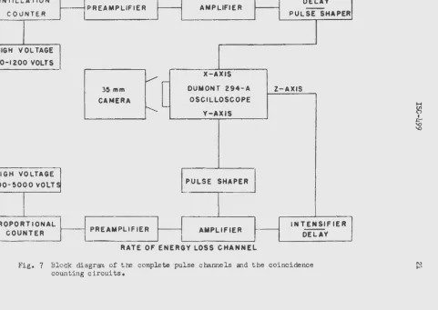
The electrcnic circuitry requirements of this problem were essentially pulse amplification, pulse shaping, pulse delaying, llld coincidence counting. Figure 7 is a block diagram of tre complete pulse·channels and the coinci-dence counting circuits. Voltage pulses arising in the two counters from traversal by a particle were amplified to 0-50 volts and shaped to satisfy the requirenents of the coincidence circuit. To improve the resolving time of the coi~1cidence circuit, total pulse duration in tre scintillation counter channel was restricted to one microsecond. With the coincidence
counting method employed, the resolving time of the coincidence circuit was approximately 0.75 microseconds. Delaying pulses from the proportional counter indicated a negligible accidental coincidence counting rate with the source activities used.
The multiple-wire proportional co.unter was operated from a 1000-5000 volt regulated power supply designed by W. A. Higinbothaml9. With gas fillings of 91 per cent argon and 3 per cent
co
2 at pressures below atwospheric pressure, operation of the counter with gas gains of 102-loJ required voltages of 1000-2000 volts. Voltage pulses from the counter
were amplified by an Atomic Instrument Company mo<.:el 205B preamplifier and
a model 204C amplifier. The preamplifier had a rise time response of 0.2
microseconds and a fixed gain of 20. The amplifier had an input time constant, adjustable step-wise, of 0.16 to 16 microseconds; a rise time,
adjustable step-wise; of 0.2 to 2 microseconds;. and a gain, depending upon
the previous adjustnents, of 1600-9000. With a ccnstant pulse height
source md a precision step-attenuator, linearity of the complete
propor-tional counter amplification channel was determined to deviate less than two per cent from absolute linearity at the higher voltages of the 0-50
volt pulse height interval. Output pulse heights were determined by
single channel pulse height analysis. The maximum limit of tre amplifier
nonlimarity was within the limits of error in determining the most
ENERGY CHANNEL
SCINTILLATION DELAY
PREAMPLIFIER AMPLIFIER
-COuNTER PULSE SHAPER
HIGH VOLTAGE
400-1200 VOLTS
V.-
X-AXIS35 mm DUMONT 294-A Z-AXIS
CAMERA OSCILLOSCOPE
..._"-Y-AXIS
HIGH VOLTAGE
PULSE SHAPER
I
1000-5000 VOLTS
-·
PROPORTIONAL INTENSIFIER
COUNTER PREAMPLIFIER
l
AMPLIFIER DELAY-
-RATE OF ENERGY LOSS CHANNEL
Fig.
7
Block diagram of tre complete pulse channels and the coincidence counting circuits.H ~
I
l="'
' 0 ' 0
1\)
[image:23.551.70.614.76.469.2]+HIGH VOLTAGE(400-1200V)
ALL47K
0.1 Meg
10\
• • ''9 '
o.ol,...td
PLATE
1
~ALL
0.05JLfd
• •
[~7 ~
-
a..
~ t-:
• •
liG
S
~
0
1-0
J:
a..
en
(X)
lO
<{
(.)
a::
CATHODE
+210V
6J4
OUTPUT
AMPHENOL 4-PIN MALE
o.os,...td
6.3V
:~
Fig. 8 Schematic diagram of photomultiplier dynode and scintillation counter cathode follower circuits.
N 1\.)
H U'l
n
I
I="
\Q
[image:24.555.25.669.63.467.2]ISC-499 23
The dynode circuit (Figure 8) of the RCA-5819 photomultiplier used in the scintillation counter was powered from a 400-1200 volt full-wave
rectified, regulated power supply. After initial warm up, stability better than 0.1 per cent was observed. Attempts to operate
tre
dynode circuit with a negative high voltage power supply, whereby it would be possible to couple directly the photomultiplier output to the preamplifier, failed, because i t was discovered that spurious pulses arose from discharges between the negative potential photocathode and the grounded sleeve which was the mounting for the scintillation counter J:e ad. Thus, the photocat:OOde was grounded, a positive high voltage supply was used, and the photomulti-plier signal was capacitively coupled to the grid circuit of a cathode follower (Figure8).
The input time constant of the grid circuit, adjust-able with the 50K potentiorreter in the grid circuit, was adjusted forapproxima.tely one microsecond total pulse duration for improved coincidence resolving tine. The
6J4
cathode follower was of convention~ design am was coupled to a pulse amplifier designed by W. A. Rhinehart of this laboratory. The linearity of t:te scintillation counter channel was deter-mined by the same method as was used to determine the linearity of the proportional counter channel. No deviations greater than two per cent were observed at the higher voltage in the 0-50 volt interval.In the section LITERATURE AND EXPERIMENTAL METHODS a method of electronically duplicating a Cartesian coordinate plot was outlined, but a more detailed explanation is desirable. Pulses arising from a particle traversing the counter telescope, after correct coincidence timing and shaping, were coupled to the horizontal and vertical plates of a Dumont 294-A oscilloscope. Coincident pulses displaced the static beam position to points along the axes pr6portional to the incident pulse amplitudes. Pulse shaping, giving the counter pulses essentially a square wave form, kept the beam position fixed during maximum pulse amplitude, a period shorter than one microsecond. A Z-axis intensifying circuit, triggered by the proportional counter pulses, intensified the maximum beam displace-ment position during this interval. The duration of the intensification was approximately 0.1 microsecond, with variations dependent upon the static beam intensity before intensification.
A pulse sha.ping circuit, which maintained pulse amplitude
propor-tionality and which quite satisfactorily shaped the pulses, is schematically shown in Figure 8a. Adjustment of the 500K p~tentiorreter determined the zero slope during maximum pulse height. Since the oscilloscope employed had a built-in delay in the Y-axis amplifier and not in the X-axis amplifier, a 0.4 microsecond delay line (Figure 8a) was introduced in the scintillation counter channel.
Data were recorded photographically using both single frames and moving film. For photographic recording of characteristic particle loci, long exposure single frames were taken with a
35
rnm.,
f3.5
DumontINPUT
Zc= 10000
...., 0.4psec. DELAY
LINE
IN 55
IN34
DELAY
I
PULSE SHAPER
IOOppf
Fig. 8a Schematic diagram of pulse shaping circuit and scintillation counter
0.4
microsecond deJa Y•OUTPUT
1\) ~
H
(/l
0
I
~
[image:26.552.24.655.78.431.2]ISC-499
25
analysis at a particular energy interval, the oscilloscope was masked, except for the desired energy interval, and an oscilloscope recording camera with moving film was used to record the intensified "dot" spectrum. Spectrum analysis was done on the Iowa State College pulse height analyzer.
The pulse shaping techniques, coincident oscilloscope pulse display, Z-axis intensification circuitry, and the method of pulse height analysis utilizing a 35 mm. f+lm record have been reported by Hunt, Rhinehart, Weber, and Zaffarano •
INVESTIGATION
The practicability of particle detection m d identification by tte method considered was determined by examination of the characteristic particle loci and the energy loss spectra at several energies. Oscillo-scope display of the characteristic loci of protons, deuterons, and
cX.-particles were Photographed for a qualitative indication of the particle separation. A definite identification of the 0(. -particle locus was found from photographing t re loci, and hence' a qum ti tative proof of the
oL
-particle separa.tion was not necessary. However, a relatively small separation of the loci of protons and deuterons was found, and qumtitative examination of the energy loss spectra for protons and deuterons wasrequired. From observation of the energy loss spectra a decision of the practicability of separating the particle groups by the method was made.
Procedure
Heavy charged particles were obtained from ."\ Pu2
39
CJt(; -particle source(5.16 Mev) and elastic scattering of 0-10.3 Mev neutrons
(Po
-Be source) in hydrogenous (acrylic plastic, Lucite
or Plexiglas) and deuterated(paraffin) materials. The ejection of protons and deutE:rons by scattering of neutrons is known as tre "knnck-on 11 process. • It can be shown for
nonrelativistic energies that protons are ejected in tht3 forv1ard direction with energies equivalent to the energies of the incident neutrons;
deutrons are ejected with energiet equal to eight-ninths the energies of the incident neutrons.~ The ~otal neutron intensity of the Po -
Be
source was estimated to be 10/ - 10 neutrons per seccnd. With this order of intensity, identifiable numbers of protons and deuterons were emitted, but pulse height analysis of the energy loss spectra in ~ given small energy interval required six hours of film recording to register 5000 - 10,000events. Low source intensities hampered extensive energy loss spectra analysis, since intensities were negligible above
5
Mev. Thus, no data were taken in the range 5-10 ~v. To take advantage of maximum counting rates, a. single target or source was placed in the scattering chamber during each run.26
ISC-499the
5.16
~V o<,-particles from Pu239. Taylor, Jentschke, Remley, Eby1and Krugerlb have measured the response of Nai(Tl) to heavy particles. From treir data, the energies of heavy particles for equivalent pulse heights can be determined. For pulse heights equivalent to those of
5.16
Mev ~-particles in Nai(Tl), protons and deuterons have 2.7 and 2.0 Mevenergies, respectively. At twice the pulse height for the same oG. -particles, protons and deuterons have energies of
5.0
and4.5
Mev, respectively.Since these values were determined grfghically and do not account for the experimental errors of T~lor, et al. , their accuracy below 10 per cent must be questioned. Thus, energy loss spectra were analyzed at 2.7+0.3 and
5.0+0.5
Mev for protons and 2.0+0.2
and4.5+0.5
Mev for deuterons.The
oC'
-particle source used for calibration was evaporated on a small diameter foil placed in contact with the freshly polished crystal of the scintillation counter when the counter was assembled.Iesults
Operating the proportional counter with an argon (97 per cent) and
CO~ (3 per cent) gas mixture at 18 em of mercury~ the o(. -particles of Pu 39 were resolved as a locus shown by the oscilloscope photograph, Figure
9.
(In the oscilloscope photographs, Figures9
through11,
the dark vertical line, arising from proportional counter pulses not in coin-cidence with the scintillation counter, defines the energy loss (-dE/dx) axis. The static beam position is at the lower left, and a line drawn perpendicular to the -dEjdx axis and through the static beam position would define the energy E axis.) A photograph (not shown), similar to Figure9
taken with protons and <X. -particles being counted at the sametime, showed a wide separation of the loci, as was expected from the wide margin between the rates of energy loss for the particle types.
The loci and energy loss spectra of protons and deuterons at the energy intervals previously mentioned were studied with an argon and
co
2 mixture at 60 em of mercury pressure. Higher gas pressures were not usedto
prevent possible rupture of the mica window isolating the counter chamber. Figures 10 and 11 are photographs of the loci of protons and deuterons, respectively, taken with identical conditions. Figure 12 is a composite of Figures 10 and 11 and indic<.1.tes an overlapping of theclosely lying loci. However, contrary to expectations from the theory of statistical fluctuations of energy loss, the deuteron locus appeared to have a greater spread than the proton spread at the same energy. Pulse analysis of the energy spectra verified the greater spread but a non-Gaussian distribution raised justifiable doubt about its cause. This point will be discussed after considering the energy loss spectra.
ISC-499
Fig.
9 Oscilloscope photograph of
charac-teristic
o<.-particle loci.
Fig. 10 Oscilloscope photograph of
characteristic proton loci.
27
Fig. 11 Oscilloscope photograph
of characteristic deuteron
loci.
[image:29.554.38.535.36.698.2]400~---~
(/) ~
z
:::>
0
(.)
0
.
110
:!:
0.010 Mev
300
l
100
0
o
10
20
30
40
50
60
PULSE
HEIGHT {ARBITRARY)
Fig. 13 Energy loss spectrum of 2. 7 Mev protons, which have traversed l
em of argon (97 per cent) and
co
2 (3 per cent) at a pressure of60 em of mercury.
(\.)
CXl
~
0
I
ti;
[image:30.556.33.632.76.469.2]ISC-499
29
2.4 - 3.0 M:lv protons. The distribution w.as Gaussian with a width at half-maxinru.m of
48
per cent. The most probable energy loss6
was determined from tre range-energy curves of Aron, Hoffman, and WilliallB to be 0.110 Mev for the median energy, 2. 7 M3v, of the energy interval. This value must be considered uncertain by a value dependent upon tre probable lossat the energy interval limits. In tre latter case, the uncertainty was 0.010 Mev. The probable error in counting is indicated for the maximum counting rate. Figure 14 is a similar energy loss spectra for the energy interval
4.
7 -5.3
Mev. The counting statistics were wo poor to decide the spectrum shape, but within the limits of probable error the distribution is Gaussian, with a width at half-maximum of55
per cent.Deuteron eD~trgy loss spectra were measured with the same counter fillings and pressures as were used for protons. Spectra were analyzed at energy intervals 1. 7 - 2.3 Mev and
4 ..
2 -4.8
Mev. Figures 15 and 16 are the results of the analysis. The skewness on the low energy side of both spectra shows a consistent irregularity, though lying nearly within the probable error. It is believed the ·irregularity and the skewness of tre distribution was caused by neutron scattering from hydrogenous material in the counter chamber. Justification for this conclusion is that the ratio of the mean pulse height of the stray counts to the mean pulse height of the true deuteron counts is roughly1. 7
in both Figures15
and 16. The ratio is in agreement with the ratio of deuteron to proton energy lo=?s determined from the work of Aron, et al. The counting statistics are not sufficient ta make a definite conclusion, but all evidenceindi-ca~s that loci spread arises from stray reactions. The mica entrmt window is bonded with 1raldite resin and conceivably was the stray source o! protons. Protons which arose near the counter window traversed the proportional counter diagonally and could have produced the observed
S:FeC-trum spread, thereby smearing the two particle loci observed photographi-cally in Figure 12. Fitting a Gaussian distribution curve
to
the undis-torted component of the deuteron energy loss spectrum showed a distribution width of the same order of magnitude as the spectra widths-observed for the proton energy losses.The plotted spectra of proton and deuteron energy losses are indivi-dually labeled with their probable error and their most probable energy loss. The fitted curves were drawn through the experi~ntal points within the limits of probable error.
Conclusions
The energy loss spectra -widths, obtained experi~ntally at 2.
7
and 5.0 Mev for protons and at 2.0 and 4.5 &v for deuterons, had a greater width than was expected from tlEoretical considerations. A theoretic~l fit of the experi~ntal data was not made since the calculations of Symon were not directly applicable at the energies considered. No asymmetry greater
20~---0.070
t
0.010
Mev
150
l
•
•
CJ)
100
t-z
~
0
(.)
50
0
o~---,o~----~2~o----~3o~----~4~o----~5o~----~s~o---7~o~~
PULSE HEIGHT (ARBITRARY)
Fig.
14
Energy loss spectrum of5
.o
Mev protons, which have traversed lem of qrgon (97 per cent) and C02 (3 per cent) at a pressure of
60 em of mercury.
w
0
H
en
0
I
~
; (/)
1-z
::)
0
0
0
0.120
:t
0.010 Mev
l
10
20
30
40
50
PULSE HEIGHT (ARBITRARY)
Fig. 15 Energy loss spectrum of 2.0 Mev deuterons, which have traversed 1
em of argon (97 per cent) and
co
2 (3 per cent) at a pressure of 60em of m=rcury.
60
H ~
l:-'0 '0
[image:33.553.38.695.57.459.2]\..t.)
400~---~
300
en
t-200
z
:::>
0
0
0. 210
t
0.030Mev
j
0---~----~---~----~---~----~~
0
10
20
30
40
50
60
PULSE
HEIGHT (ARBITRARY)
.Fig. 16 Energy loss spectrum of
4.5
fo~Ev deuterons, which have traversed lem of argon (97 per cent) and C02 (3 per cent) at a pressure of 60
em of roo rcury.
70
w
1\)
H
~
I
~
ISG-499
33
that the effect would not be detrimental to particle irentification in the interval 0-5 Mev. However, as has been shown theoretically, the effect of high energy loss collisions and the· resulting distribution asymmetry becomes more pronounced at energies near 10 M9v for the energy lost in 1 em of the stopping I~Edium employed experimentally (argon at
60
em of mercury). The distribution widths observed were exaggerated by analyzing the energy loss in a 0.5 l'.tev interval rather than in a much smaller increi~Ent. Also, limited counter resolution introduced additional width.With energy loss spectra widths of the order of
So
per cent, a.s found experizoontally, complete separation of all 0-10 Mev protons and deuterons by the method considered is not possible since the proton and deuteronspectra overlap. However, the presence of particle types can be detected by masking all but the major component of the desired particle group on the oscilloscope and photogra.phically recording the "dot" spectrum. This method, though reducing the counting efficiency, preserves the energy spectrum and the particle identification. Utilized in this
manner,
the method is practical for the detection and identification of heavy charged particles from photonuclear reactions.SUMHARY
The practicability of a method of heavy charged particle detection and identification in the energy interval 0-10 Mev for protons, deuterons, and
<X. -particles was considered. Particle identity was based on coincidence detection of a particle traversing a pair of telescoped counters. Rate of energy loss (-dE/dx), detected in a low stopping power gas-filled propor-tional counter, and energy (E), detected in a Nal(Tl) scintillation counter, were measured. Oscilloscope display on the X and Y axes of the coincident pulses of rate of energy loss and energy and Z-axis intensification at the time of maximum pulse amplitude permitted electronic duplication of the rate-of-energy-loss versus energy curves, which are characteristic of particle types. Photographs are shown of the characteristic loci of the particle types. No difficulty was encountered in ~ -p<lrticle identifica-tion, but separation of proton and deuteron loci was hindered because of statistical fluctuations in energy loss. To determine its effect on
particle identification, the statistical fluctuations in the energy losses of protons and deuterons in passing through 1 em of 97 per cent argon and
3
per cent C02 at 60 em of mercury (absolute pressure) were observed. Proton energy losses were observed at 2.7 and 5.0 Mev; deuteron energy34
ISC-499LITERATURE C !TED
1. A. K. Mann md J. Halpern, Phys. Rev. 82, 733 (1951).
2. J. C. Keck, Phys. Rev.
85,
410 (1952).3.
W.
S. Gilbert and J.W.
Rosengren, Phys. Rev. 88, 901 (1952).4.
J.
W.
Rosengren and J.M.
Dudley, Phys. Rev. 89, 603 (1953).5.
M.
S. Livingston and H. A. Bethe> Rev. MOd. Phys.2,
245 (1937).6. W. A. Aron, B. G. Hoffman, and F.
c.
Williams, Range - energy curves,Atomic Energy Commission Report AECU-663, (1952)o
1.
W. A.
Hunt,w.
Rhinehart, J. Weber, and D. J. Zaffarano, a multichannelpulse height analysis system utilizing a
35
mm. film record. AmesLaboratory Report ISC-359. 1953.
B.
L. Landau, J. Phys. (USSR)~, 201 (1944).9.
K. R. Symon, Statistical fluctuations in energy loss. UnpublishedThesis. Harvard University Library. (1948).
10.
11.
12.
P. Rothwell, Proc. Phys. Soc. (Lond.) 6LB, 911 (1951).
G. J. !go, D. D. Clark, and R. M. Eisberg, Phys. Rev.
89,
879 (1953).B. Rossi, Hi~-Energy Particles (Prentice Hall, Inc., New York, 1952),
PP• 29- •
13. B. B. Rossi and H. H. Staub, Ionization Chambers and Counters (McGraw-.
Hill,Inc., New York, 1949), pp. 97-lOO.
-14.
W. Franzen, R. W. Peele, and R. Sherr, Phys. Rev. 79, 742 (1950).15. H. B. Frey,
w.
M. Grim,w.
M. Preston, and T. S. Gray, Phys. Rev. 821372 (1951).
16.
c.
J. Taylor, W. K. Jentschke, M. E. Remley, F. S. Eby, and P. G.Kruger, Phys. Rev. 84, 1034 (1951).
17. J. G. Likely and W. Franzen, Phys. Rev. 87, 666 (1952).
18. A. Guthrie and R. K. Wakerling, Vacuum Equi}ment and Techniques