Abstract: Fuel injection system is an indispensible part of the present day automobiles. The depletion of the fuels along with continuous surge in the fuel prices has made it imperative to use fuel economically and restricting the wastage to a minimum. Contrary to the carburetor, using predefined amount of fuel irrespective of the environment, Fuel Injection System uses just the required amount of fuel based on the operating conditions as sensed by the Engine Control Module (ECM). Numerous parameters are required to be sensed by the ECM to achieve optimum efficiency of the engine. To handle the processing of such large number of parameters, a robust architecture is required. This paper presents the design and implementation of ECM utilized in Electronic Fuel Injection (EFI) system on a Field Programmable Gate Array. The ECM architecture discussed in the proposed system is computationally efficient enough to fulfill ever-increasing functionalities of the ECM. The main objective of this research is to sense the parameters required for the ECM analysis and to interpret and analyze this data and accordingly control the solenoid (actuator). The CAN controller is also deployed in an FPGA to facilitate the communication between ECM and Human Machine Interface (HMI) to indicate the parameters sensed by the sensor on the LCD. The target device (FPGA) for this work is Xilinx Spartan 3E and the design tool is Xilinx ISE 14.7 with the ECM and CAN controller being modeled in Verilog Hardware Description Language (HDL).
Index Terms: Engine Control Module (ECM), Electronic Fuel Injector (EFI), FPGA, Sensors, Solenoid, CAN Controller
I. INTRODUCTION
Few decades earlier, a vehicle was a profoundly mechanical piece of equipment consisting of an engine, a drive component, wheels, battery, alternator framework and a few controls for the lights as the main electrical parts. Initially Processing element utilized in automobiles were a small microcontroller for controlling spark plug timing, with function for this control being executed in a couple of lines of code [1]. Improvements in electronics permitted this capability to be stretched out to engine timing control, fuel injection control, and control of diesel engine, utilizing more complex and robust microcontrollers which executed code that processed data obtained from numerous sensors and accordingly controlled actuators. The widespread employment of microcontrollers in engine control systems led to the development of potent and exhaustive computational devices referred to as Engine Control Units [2].
Revised Manuscript Received on August 05, 2019
Surabhi Ghatole, School of Electronics and Telecommunication, Maharashtra Institute of Technology World Peace University (MIT-WPU), Pune , India
Harshali Zodpe, School of Electronics and Telecommunication, Maharashtra Institute of Technology World Peace University (MIT-WPU), Pune , India
Prior to the introduction of ECM; Carburetors were used for injecting fuel inside the cylinder. These were replaced by fuel injection system owing to several benefits as compared to carburetor. Some of the benefits of the fuel injectors are higher power output, greater fuel efficiency and much lower emissions.
Earlier complex calculation were commonly not required, unwavering quality progressed towards becoming a significant factor. At the point when units needed to communicate, they were connected by wires. Contemporary vehicles, requires considerably more complex calculation and dedicated system based network to deal with the complex exchange of information.
Microcontrollers with incorporated CAN interface endure an execution penalty, as the microcontroller is responsible for message transmission and receiving, other than examining inputs and driving outputs. This is a serious factor in modern systems, where latency is an issue. If independent CAN controller is utilized, there is a cost overhead as an additional IC is required, expanding the expense of the framework. Reconfigurable processing elements like Field Programmable Gate Arrays (FPGAs) can be used as the possible alternative. The re-configurability of the FPGA permits designers to manufacture customized circuits having high efficiency and low power consumption, along with having the benefit of flexibility of software system. Along with the execution support, such frameworks give a platform for realizing various circuit on same equipment with complete segregation, utilizing hard partitioning, and partial or complete reconfiguration. This additionally results in reduction in cost as well as power consumption. Besides, FPGA’s empower frameworks to be worked with ensured deterministic outcomes. This is especially significant for modern in-vehicle frameworks, where reliability is of principle significance.
In this paper, the functionality of the fuel injector which is one of the important applications of the ECU is demonstrated. FPGA is being used as a processing element for analysis with use of different sensors like temperature, Pressure and Engine speed sensor. CAN communication is established between the ECM and Human Machine Interface (HMI) for notifying the user about sensor outputs.
FPGA Based Engine Control Module for Fuel
Injection System
II. SYSTEM OVERVIEW
[image:2.595.50.274.56.253.2]A. OVERVIEW OF ENGINE CONTROL UNIT
Figure 1: Engine Control Module [3]
An Engine Control Unit (ECU) is considered as an “electronic brain” that ensures optimum performance of an engine. In order to achieve peak efficiency ECU has to directly or indirectly control various different modules or parameters. Some of the parameters that ECU controls are air/fuel ratio, ignition timing, idle speed, variable valve timing. To control above mentioned parameters ECU acquires inputs from sensors located at different positions in the vehicle. Depending on the data received from sensors ECU provides output parameters to control the actuators.Some of the most commonly used sensor inputs for ECU are air temperature sensor, coolant temperature sensor, throttle position sensor, manifold pressure sensor and engine speed sensor. Information obtained from sensors is processed and this processed signal is sent through ECU’s output to control fuel and ignition system. The processed signal informs the injectors about the quantity of fuel that needs to be injected so that required air-to-fuel ratio is achieved. It also notifies spark plug about the appropriate time to ignite the fuel for complete combustion of air-fuel mixture.
B. OVERVIEW OF FUEL INJECTOR SYSTEM
The fuel injection system used in the Compression Ignition (CI) engines is one of the most crucial elements of the vehicular engine. The performance of the fuel injector largely dictates the performance of the engine. The power output, economical consumption of fuel is all controlled by the output of the fuel injector. Fuel injector carries out the principal task of controlling and initialization of the combustion process. The infusion of fuel in the combustion engine at the end of the compression stroke leads to the atomization of the fuel into very fine droplets. Surface area of droplets of fuel is increased by atomizing it into very fine droplets, enabling complete combustion caused by efficient mixing of air and fuel. The process of atomizing the fuel is performed by forcing the fuel through a tiny orifice which is subjected to a heavy pressure. The heat transfer from the air fuel moisture and compressed air causes the vaporization of these droplets. Constant heat transfer from the compressed air to the fuel consequently increases the fuel temperature and eventually exceeds its self ignition temperature value. This initiates the process of fuel combustion owing to the spontaneous ignition of the fuel. A well designed fuel
injector assures rapid and exhaustive combustion of the fuel which is essential for the optimum utilization of the injected fuel. The injector module comprises of a needle valve, a compression spring, a nozzle and an injector body. All these components working in cohesion constitute the fuel injector.
C. DESIGN OVERVIEW OF THE PROPOSED SYSTEM
In this research Spartan 3E is used for ECM analysis which is used inside the fuel injection system. The primary reason for selecting Spartan 3E is the large number of I/O pins it provides for interfacing multiple sensors. Additional advantages associated with FPGA as compared to other architectures are high efficiency, cheap, partial or complete reconfiguration and hard partitioning of modules [4]. The proposed system takes input from three sensors namely temperature, pressure and engine speed sensor. ADC MCP3204 is used for converting analog input from sensors to digital. As this ADC used is an SPI based ADC; code for SPI is written in Verilog HDL and deployed in an FPGA to facilitate communication between the ADC interfacing board and FPGA. PWM signal is generated to control the solenoid whose duty cycle is varied in accordance with the sensed parameters.
Code for CAN controller is written in Verilog HDL and is deployed in an FPGA. CAN controller is used to establish communication between ECM and HMI. Sensor outputs indicating temperature of the intake air, fuel pressure and engine RPM values are given as input message to CAN controller.
The proposed work is developed and implemented in Xilinx ISE 14.7 Design Suite and is coded in Verilog HDL. The functionality of the design is verified in simulation using ISim simulator and is physically verified by downloading the code on a Spartan 3E FPGA.
III. METHODOLOGY
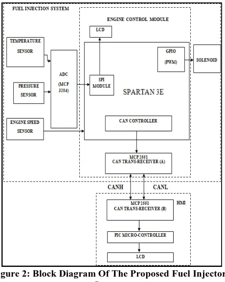
In this section the block diagram of the proposed Fuel Injector system given in Figure 2 is explained in detail.
Figure 2: Block Diagram Of The Proposed Fuel Injector System
Analog values need to be converted to digital form to be processed by FPGA. Outputs of the aforementioned sensors are analog in nature and require conversion to digital form to allow for further processing. ADC MCP 3204, a successive approximation 12-bit ADC programmed for four single ended inputs (channels) is used in our work. This ADC uses serial peripheral interface (SPI) protocol to communicate with the devices and has conversion rate of up to 100ksps and operates in the range of 2.7 volts to 5.5 volts. [7]. The SPI communication protocol is coded in Verilog HDL and deployed in an FPGA to facilitate communication between the ADC interfacing board and FPGA.
The digital output from the ADC is processed by the FPGA to generate the PWM signal which in turn controls the solenoid valve. The duty cycle or the pulse width of the PWM signal will determine the ON time of solenoid.
The FPGA also houses a 16*2 LCD module which displays the temperature and pressure values from the sensors. FPGA also acts as the master to transmit the sensor data to the slave or receiver module using the CAN communication protocol. The FPGA considered for our implementation is Xilinx Spartan 3E. The XC3S500E have 500K system gates 10476 equivalent logic cells,73k distributed RAM bit’s,360K block RAM bit’s, 232 maximum user I/O and 92 maximum differential I/O pairs [8]. The receiver node is PIC18F4520 microcontroller. The MCP2551 CAN transceiver module is used for both transmission and reception purposes.
IV. EXPERIMENTAL SETUP
Engine used for this research work was a 4 stroke single cylinder engine. It had a rated power of 5 HP at 1500 RPM. Temperature sensor was used for monitoring the temperature of the intake air. Pressure sensor was used for measuring the fuel pressure in the tank. Engine speed sensor was used for indicating the RPM value of the engine.
Specifications of the engine on which this ECM was tested are as follows:
Engine: Cummins diesel engine with D.C generator Injection timing : 280 BDC
Compression ratio : 16.5:1 Orifice diameter : 20mm Maximum H.P : 5 H.P Stroke : 110mm Bore : 80mm Type : water cooled
Maximum load of engine: 15.252 amps
V. IMPLEMENTATION RESULTS
In this section, the implementation results of the proposed system and CAN controller is presented. These implementations are simulated and verified using ISim simulator. The main module consists of several sub modules such as ADC interfacing, LCD interfacing, PWM generator and CAN controller. The functionality of the implemented CAN controller is verified in simulation using ISim simulator before deploying it in an FPGA. The CAN controller implemented is compatible with CAN 2.0B. The identifier used for assigning priority to message being sent is of 11-bit. Results obtained in simulation are shown in figure 3.
Figure 3: Simulation results of CAN controller Figure 4 shows the implementation setup of the proposed system.
[image:3.595.305.557.362.488.2] [image:3.595.308.556.543.710.2]Table 1: Relation between different ECM parameters Boost
pressure (psi)
Engine speed (RPM)
PWM (%)
5 626 20.32
13 712 22.4
18 800 26.32
21 903 32.98
27 1000 38.5
32 1200 40.8
38 1304 42.45
44 1400 42.85
58 1513 43.25
72 1600 45.65
81 1702 46.22
87 1800 46.5
93 1914 46.71
95 2002 47.98
100 2100 48.5
From the results given in table 1 shows the relation between engine speeds, boost pressure and duty cycle of PWM signal generated for solenoid operation.
The duty cycle of PWM signal is calculated using the formula:
Duty cycle = (Ton/Ton+ Toff ) x 100% (1) Where, Ton is the duration for which the signal is high and Toff is the duration for which the signal is low.
It was observed from the table that the as the engine speed increases the fuel pressure increases and hence the duty cycle of the PWM signal applied to the fuel injector increases.
Figure 5: Graphical representation of the relation between sensor output and duty cycle of PWM
The Figure 5 shows the graphical representation of PWM output with respect to Pressure and Engine speed sensor. Figure 6 shows the sensor outputs at the transmitting side of CAN network where M gives the engine speed in RPM, T gives the temperature and P represents the sensed pressure value. From figure 7 it can be seen that the LCD connected to
[image:4.595.306.550.85.245.2]microcontroller which represents the receiving end of the CAN network displays similar values of sensed parameters as displayed on the transmitting side LCD shown in Figure 6.
[image:4.595.306.547.280.443.2]Figure 6: LCD displaying the sensor output at the transmitting end of CAN network
Figure 7: LCD displaying the sensed output at the receiving end of CAN network
VI. CONCLUSION
Engine Control Module is the heart of the Engine Management System. Conventional ECMs using microcontrollers as the processing element have several drawbacks as compared to FPGAs. In this paper the implementation of Fuel injector, an application of ECM on FPGA is discussed. A robust and efficient ECM architecture cable of sensing and processing large number of parameters is proposed. From the results obtained it can be inferred that FPGA can be used as an alternative to microcontrollers for implementing the ECM to exploit additional features inherent to FPGA. CAN protocol is used to establish communication between ECM and HMI for indicating the sensor outputs.
ACKNOWLEDGMENT
[image:4.595.47.283.465.673.2]REFERENCES
1. Jonas Bereisa. Applications of Microcomputers in Automotive Electronics.Transactions on Industrial Electronics, IE-30(2):87{96, May 1983.
2. Shreejith Shanker, Enhancing Automotive Embedded
3. Systems with FPGAs, Nanyang Technological University, April 2016. 4. Ilakkiya B, Vanitha V, “A Survey on Engine Control Unit”, IJARIIE,
2016.
5. Suresh Chandra Sathapathy,Vikrant Bhateja, Amit Joshi, “ Proceedings of the international Conference on data Engineering and Communication Technology”, ICDET,2016.
6. Texas Instrument “LM35 Precision Centigrade Temperature Sensors”, LM35-Datasheet, August 1999 [Revised December 2017]
7. Interlink Electronics, “FSR 400 Series Round Force Sensing Resistor” Force sensing resistor Datasheet.
8. Microchip Technology, “2.7V 4-Channel/8-Channel 12-Bit A/D Converters with SPI Serial Interface”, MCP3204-Datasheet.
9. Logsun Systems, “FPGA SPARTEN 3E WITH UNIVERSAL
BOARD”.
10.RatanR. Tatikonda, Vinayak B. Kulkarni, “FPGA based Exhaust Gas Analysis for Automotive Vehicles” IEEE International Conference on Internet of Things and Applications (IOTA), 22-24 Jan 2016, India. 11.Vaibhav Bhutada1, Shubhangi Joshi2, Tanuja Zende3, “Design and
Implementation of CAN Bus Controller on FPGA”, International Journal for Research in Applied Science & Engineering Technology (IJRASET), December 2017.
12.Dong Hui, Huang Bo, Wang Dafang, Zhao Guifan, ‟The ECU control of Diesel Engine based on CAN”, International Conference on Intelligent Computation Technology and Automation (ICICTA), pp734-736,2011.
AUTHORS PROFILE
Surabhi Ghatole has completed her B.E. degree in Electronics and Telecommunication from Yeshwantrao Chavan College of Engineering, Nagpur in 2016. She is currently pursuing M.Tech in VLSI and Embedded systems from MIT World Peace University, Pune. Her area of interest is Very large Scale Integrated (VLSI) design.
![Figure 1: Engine Control Module [3]](https://thumb-us.123doks.com/thumbv2/123dok_us/8187386.256724/2.595.50.274.56.253/figure-engine-control-module.webp)