ABSTRACT
ABSTRAK
DEDICATION
Specially dedicated to
ACKNOWLEDGEMENT
Alhamdulillah, praise be to Allah for His blessings and giving me the strength along the challenging journey of completing the project. Primarily, I would like to take this opportunity to express my deepest gratitude towards my project supervisor, thank my supervisor, Mr. Mohd Hisham b. Nordin who has persistently and determinedly assisted me during the project. It would have been very hard to complete this project without the passionate supports and guidance encouragement and advices given by him.
My outmost thanks also go to my family who has given me support throughout my academic years. Without them, I might not be able to become who I am today. I am grateful to have love affection and care from all of my family members as well. My fellow friends should also be recognized for their continuous support and encouragement.
TABLE OF CONTENT
Abstract i
Abstrak ii
Dedication iii
Acknowledgement iv
Table of Content v
List of Table viii
List of Figures ix
List Abbreviations x
1.0 INTRODUCTION 1
1.1 Background 1
1.2 Problem statement 2
1.3 Objectives 2
1.4 Scope of Project 2
2.0 LITERATURE REVIEW 3
2.1 Introduction 3
2.2 Mobile Robot 3
2.2.1 Classification 4
2.2.2 Mobile Robot Navigation 4
2.2.2.1 Manual robot or Tele-Op 4
2.2.2.2 Guarded tele-op 5
2.2.2.3 Line-following robot 5
2.2.2.4 Autonomously randomized robot 5
2.2.2.5 Autonomously guided robot 5
2.2.2.6 Sliding autonomy 6
2.3 Movement 6
2.4 Lifting Tire Mechanisms 7
2.5 Detection Mechanism 10
2.6.1 Microcontroller 11
2.6.1.1 Central Processing Unit (CPU) 11
2.6.2 Programmable Logic Controller (PLC) 13
2.7 Summary of Chapter 2 13
3.0 METHODOLOGY 14
3.1 Introduction 14
3.2 Development process flowchart 15
3.2.1 Explanation of the development process flowchart 16
3.2.2 PSM 1 and 2 Gantt Chart 17
3.2.3 Fabrication Process for The Platform 18
3.2.4 Circuit Design 18
3.2.5 Programming 18
3.2.6 Testing And Analysis 19
3.3 Parts Selection 20
3.3.1 Mechanical Structure Parts 20
3.3.1.1 Tire 20
3.3.1.2 Aluminium Angle 21
3.3.1.3 Acrylic 22
3.3.2 Electrical and Electronic Parts 23
3.3.2.1 Battery 23
3.3.2.2 DC Motor 24
3.3.2.3 Microcontroller 25
3.3.2.4 Relay 26
3.3.2.5 Limit switch 27
3.3.2.6 Transistor 28
3.3.2.7 Protoboard 29
3.3.2.8 Voltage Regulator 30
3.3.2.9 Capacitor 31
3.4 Preliminary Design of the Project 32
3.4.1 Design 32
4.0 DESIGN AND DEVELOPMENT 34
4.1 Tire Lifting Platform Development 34
4.1.1 Tire lifting base design 35
4.1.1.1 Base machining process 36
4.1.2 Tire Lifting Handle Design 39
4.1.3 Sensor 41
4.2 Tire Lifting Electronic Circuit Development 43
4.3 Programming Development 46
4.3.1 Write program using microC 8.2 47
4.3.2 Simulating using Proteus ISIS 7.6 SP4 for PIC16F8777A 52
4.4 Conclusion 55
5.0 RESULT AND DISCUSSION 56
5.1 Result 56
5.2 Tire Lifting System Experiment 57
5.2.1 Initial Testing 57
5.2.1.1 Stability 57
5.2.2 Circuit testing 59
5.2.3 Obstacle Sensor Experiment 60
5.3 Discussion 64
5.3.1 Initial testing Discussion 64
5.3.1.1 Stability Discussion 64
5.3.2 Circuit discussion 65
5.3.3 Obstacle Sensor Discussion 65
5.4 Conclusion 66
6.0 CONCLUSION AND FUTURE WORK 67
LIST OF TABLES
2.1 Advantages and Disadvantages of Programmable Control 13
4.1 Electronic Component 44
4.2 Input 44
4.3 Output 45
LIST OF FIGURES
2.1 Moving Patterns on Stairs. 8
2.2 Mobile robot with Forklift-Wheels. 8
2.3 Active obstacle passing mechanism in a magnetic wheeled wall 9
climbing robot
2.4 Magnetic wheeled robot Fischer 9
3.1 Development Flow Chart 15
3.2 PSM 1 and PSM 2 Gantt chart. 17
3.3 Tire 19
3.4 Aluminium angle 21
3.5 Acrylic 22
3.6 12 volt valve regulated lead-acid rechargeable battery 23
3.7 12 volt geared dc motor. 24
3.8 PIC start up kit 25
3.9 12V Relay 26
3.10 limit switch 27
3.11 Transistor 28
3.12 Protoboard 29
3.13 Voltage Regulator 30
3.14 Capacitor 31
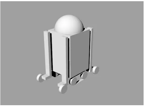
3.15 Design 32
3.16 System block Diagram 33
4.1 Engineering drawing of the tire lifting platform 35
4.2 Cutting using Hand Saw 36
4.3 Assemble the base 36
4.4 Drilling the Hole 37
4.5 Hole for the DC motor 37
4.6 Mount the motor 37
4.8 56 cm aluminium angle 38
4.9 Battery holder 38
4.10 closed view of the battery holder 38
4.11 lifting handle part 39
4.12 assemble of the tire 39
4.13 lifting handle 39
4.14 drilling the acrylic 40
4.15 hole for the 40
4.16 making the thread 40
4.17 coupling part 40
4.18 L shape of the acrylic 41
4.19 Attachment of the sensor 41
4.20 2 piece of the sensor holder 41
4.21 limit switch attached. 42
4.22 limit switch position 42
4.23 closed view of the limit switch 42
4.24 electronic circuit 44
4.25 main command in microc 47
4.26 starting the microC 49
4.27 new project 49
4.28 setup the project 50
4.29 writing the program 50
4.30 build the project 51
4.31 success message 51
4.32 start the proteus 52
4.33 ‘P’ symbol 52
4.34 search the component 53
4.35 placed the PIC 53
4.36 circuit diagram 54
4.37 select the hex file 54
5.1 tire lifting platform 56
5.2 front tires lift 58
5.3 middle tires lift 58
5.4 back tires lift 58
5.5 11.48V 59
5.6 4.99V 59
5.7 5V input 60
5.8 small and round obstacle 61
5.9 medium and square obstacle 61
5.10 high level obstacle 61
5.11 failed detection of obstacle 62
5.12 measurements the height 62
5.13 measurements the width 63
LIST OF ABBREVIATIONS
AGV - Automated Guided Vehicle ALU - Arithmetic Logic Unit CPU - Central Processing Unit D.C. - Direct Current
I / O - Input / Output
IR - Infrared
LED - Light Emitting Diode
PC - Program Counter
PCB - Printed Circuit Board
CHAPTER 1
INTRODUCTION
1.1 Background
A mobile robot is an automatic machine that is capable of movement in a given environment. Mobile robots have the capability to move around in their environment and are not fixed to one physical location. Mobile robotics the branch of robotics concerned with movable robot systems that are able to locomote within an environment or terrain. Mobile robotics and robots are mainly used in research on navigation and exploration, with applications for autonomous guided vehicles.
1.2 Problem Statement
Nowadays, mobile robot faces many critical problems and challenges in the technology today. The problems that usually occur are the mobile robot not stable when moving across an obstacle.
This mobile robot has a disadvantage when crossing the cable wire. The wheel will crash with the obstacle and make the mobile robot unstable. The purpose of this research is to create mechanism of lifting tire including mechanical structure, circuit and programming for the lifting system.
1.3 Objectives
The objectives of the project are:
a) To design and create tire lifting system for mobile robot in order to overcome the small obstacle like cable wire.
1.4 Scope of project
Scope that is covered for this project:
a) Mechanical design for tire lifting system for mobile robot platform. b) Mechatronics for tire lifting system for mobile robot circuits. c) Sensors for tire lifting system for mobile robot
CHAPTER 2
LITERATURE REVIEW
2.1 Introduction
This chapter reviews some of the previous works that have been done in the field of mobile robot technology. This section highlighted the mobile robot, classification, type of mobile robot navigation, and previous research including mobile robot development, problem that faced and mechanism of lifting tire, the common applications of lifting tire method for the mobile robot and analysis on the tire lifting the method as well as design of effective design for the mobile robot.
2.2 Mobile Robot
The autonomous robot are capable of gain information about the environment, work for an extended period, move either all or part of itself throughout its operating environment without human assistance and avoid situations that are harmful to peoples, properties, and itself. It can be found in industry, military, and security environment. Other than that, it also appears in public consumers for entertainment or to perform certain tasks like vacuum cleaning or mowing.
2.2.1 Classification
The mobile robot can be classified by the environment in which it travel and device that they use to move. First the environment in which they travel can be divide by 3 that is the land or home robot, aerial robots, and underwater robots. Second, the devise that they use divided into legged robot, wheeled robot, and tracks. In this project, the development of the project is based on the device use to move that is wheeled robot that moves in land environment.
2.2.2 Mobile Robot Navigation
There are many types of mobile robot navigation:
2.2.2.1Manual Remote or Tele-op
2.2.2.2Guarded Tele-op
A guarded tele-op robot has the ability to sense and avoid obstacles but will otherwise navigate as driven, like a robot under manual tele-op. Few if any mobile robots offer only guarded tele-op.
2.2.2.3Line-following Robot
Some of the earliest Automated Guided Vehicles (AGVs) were line following mobile robots. They might follow a visual line painted or embedded in the floor or ceiling or an electrical wire in the floor. Most of these robots operated a simple "keep the line in the center sensor" algorithm. They could not circumnavigate obstacles; they just stopped and waited when something blocked their path. Many examples of such vehicles are still sold, by Transbotics, FMC, Egemin, HK Systems and many other companies.
2.2.2.4Autonomously randomized robot
Autonomous robots with random motion basically bounce off walls, whether those walls are sensed with physical bumpers like the Roomba cleaners or with electronic sensors like the Friendly Robotics lawn mower. The simple algorithm of bump and turn 30 degrees leads eventually to coverage of most or all of a floor or yard surface.
2.2.2.5Autonomously guided robot
location-stamped, so that a hospital, for instance, can know exactly when and where radiation levels exceeded permissible levels. Such robots are often part of the wireless enterprise network, interfaced with other sensing and control systems in the building. For instance, the PatrolBot security robot responds to alarms, operates elevators and notifies the command center an incident arises. Other autonomously guided robots include the SpeciMinder and the Tug delivery robots for hospital labs, though the latter actually has people at the ready to drive the robot remotely when its autonomy fails. The Tug sends a letter to its tech support person, who then takes the helm and steers it over the Internet by looking through a camera low in the base of the robot.
2.2.2.6Sliding autonomy
More capable robots combine multiple levels of navigation under a system called sliding autonomy. Most autonomously guided robots, such as the HelpMate hospital robot, also offer a manual mode. The Mobile Robot Sinside guidance system, which is used in the ADAM, PatrolBot, Speci-Minder, MapperBot and a number of other robots, offers full sliding autonomy, from manual to guard to autonomous modes.
2.3 Movement
with Manipulator for the Manufacturing Environment. Besides that, in 1998, David P.Anderson also create small mobile robot that can be use to exploring human habitats.
Analysis of the research on a mobile robot for handling hazardous chemical by Khairul (2008) claim that modification needed in order to improve the mobile robot. First, the mobile robot need more powerful high torque motor applied with the lighter body structure to improve the robot movement. Mohd Khairul,K (2008) identified that the stability is important thing in the design of the robot to give better result of movement. In addition improvement in programming will give better result in the mobility of the robot.
2.4 Lifting Tire Mechanisms
Mobile robot has been introduced into the industry to do many tasks. Forecast indicates that this trend of using mobile robot will continue for the foreseeable future. Early research, the application research of mobile robots with forklift-driving-wheels capable to ascend and descend stairs by the Hirofumi and Noriyoshi in 1999 was concern about the mechanism in lifting the tire of mobile robot.
This research in develop the mobile robot that can lift the tire is as an alternative method to cross the obstacle. The Forklift system is a good mechanism to lift the tire. This system can be useful to be use for the mobile robot to cross the obstacle.
Figure 2.1: Moving patterns on stairs. (Hirofumi and Noriyoshi 1999)
Figure 2.2 Mobile robot with Forklift-Wheels. (Hirofumi and Noriyoshi 1999)
[image:24.612.200.442.372.550.2]