Abstract: Over the last few decades’ considerable attention has been raised on the engineering behavior of structure under the non-linear dynamic loadings like blast or impact loading. The explosions inside or near by a building leads to catastrophic damage on the building system and life. Not only the terrorist activity but also the accidental explosions like explosion of fuel tanks and LPG cylinders blast may also cause severe damage to the building structural system and leads to loss of life
In general engineers design the building for the dynamic loads like earthquake and wind loadings. But in case of blast load the shock front impacts huge load on the frontal face of structural elements. Not only the shock fronts, the reflected pressure is multiples of the shock front pressure .As a result of such extreme blast loading conditions the building will fail, because the blast load act in the duration of milliseconds. So engineers and designers are worked to develop methods to analyze and design the structures resist to the blast loads. These studies enhance to understand the response of structural system subjected to blast loads.
In this paper, two studies of concrete structures are presented. Both the studies focused on describing the response of the structural elements subjected to the blast load.
In the first study the response in the structural elements (columns and shear walls) subjected to blast load from TNT explosion result from the terrorist activity. In the second study the comparison of response in the structural elements (columns and shear walls) which is cast with different grades of concrete are subjected to blast load from TNT explosion result from terrorist attacks.
The finite element package ABAQUS was used for modelling and analyzing the elements. The analysis of the structure and structural elements subjected to blast loads require a précised in depth knowledge to understand the blast phenomenon and the non-linear dynamic response of the various structural elements. This gives a complete overview of the effects of explosion on structures.
Index Terms: Non-linear dynamic analysis, shock front, TNT explosion, Blast loading.
I. INTRODUCTION
Terrorist attacks have brought increased attention to the design of structures to resist those explosions. The latest
Revised Manuscript Received on May 06, 2019.
Jainu Karthik, Department of Civil Engineering, Godavari Institute of Engineering and Technology (Autonomous),Rajahmundry, A.P, India.
Dumpa Venkateswarlu, Department of Civil Engineering, Godavari Institute of Engineering and Technology (Autonomous),Rajahmundry, A.P, India.
Alamanda Sai Kumar, Department of Civil Engineering, Godavari Institute of Engineering and Technology (Autonomous),Rajahmundry, A.P, India.
terrorist attacks in India are the Mumbai bombing in the year 1993, the Jaipur bombings in the year 2008, the Hyderabad bombing (lumbini park and gokul chat) in the year 2007, the Dilshuknagar bombing the year 2013.
Different researchers are worked to develop précised methods to evaluate the blast pressure,A.K. Pandey (2007), M. V. Dharamapathy (2011),TM 5-1300 (UFC 3-340-02) gives detailed procedure to calculate the load on the structures when they are exposed to blast load.),B.Patil Vijay(2014), Suraj D Bhosale(2016), Arun Kumarpiyush (2018) Kirk A. Marchand(2000) worked on the response of the structure and structural elements when it subjected to blast pressure with different standoff distances.
The challenge for structural engineers is to develop methods for analysis and design of structures exposed to blasts. While the current design codes are supporting to design the structure for conventional loads and dynamic loads, but these codal data cannot predict the blast loading damage precisely. A blast load occurs in a matter of milliseconds and requires high attention, its own set of equations and criteria.
Lot of research has been done over the past five decades to develop precise methods to predict the intensity of blast loading on structures and the damage that may occur. However, until recently, the focus of the blast design will adopted for important buildings like country presidents offices and nuclear plants, genetic and biological research center’s etc., after the second world war countries around the globe are noticed the importance of blast resist structures, the focus of blast mitigation has switched from nuclear weapons to smaller attacks on the ground from terrorists. Now this thesis involves in prediction of blast loads near the ground and structural elements response to this high intensity of loading.
The main target of this study is to provide guidance to engineers and designers, where there is a need of protection against the explosions caused by detonation of high explosives. The guidance given by this thesis will describes the measures for mitigating the effects of explosions, ultimately providing protection for life, property and the structure. This thesis includes information about explosives, blast loading parameters and enhancements for blast resistant building design in the structural approach. The explosions caused by high explosives (chemical reactions) and LPG leakage blast are considered within the study. High explosives are solid in form and are commonly termed condensed explosives which release high amount of energy. TNT (trinitrotoluene) is the most widely known example.
The IS 4991-1968 and TM 5-1300(1990) is used to predict the pressure loading.
Analysis and Impact of Blast Load on Structural
Elements
Additional theoretical analysis will predict the acceleration, velocity, and deflection resulting from the blast is adopted from the Blast Risk Assessment text book by prof. K. Rama Murthy.
To provide adequate protection against explosions, the design and construction of public buildings are receiving special attention of structural engineers. Difficulties that arise with the complexity of the problem, which involves time dependent finite deformations, high strain rates, and non-linear inelastic material behavior, have motivated various assumptions and approximations to simplify the models. These models span the full range of sophistication from single degree of freedom systems to general purpose finite element programs such as ABAQUS, ANSYS work bench etc. The results from these procedures will be compared to experimental data from blast analysis in ABAQUS software.
II. EXPLOSIONSANDBLASTWAVES
A. EXPLOSION
An explosion is a phenomenon in which a very fast chemical reaction of a solid, gas or liquid that can releases very hot gases and energy takes place. The phenomenon takes place in the duration of milliseconds and it leads to release of very high temperatures and pressures
B. BLAST WAVE:
[image:2.595.317.532.52.212.2]In the detonation process the hot gases that are produced in the explosion will expand in order to occupy the surrounding available space, these gases propagation will act as similar to wave through space. These gases propagation transmitted spherically through an unbounded surrounding space. Not only the produced gases, the air around the blast area also expands and its molecules starts ramp up, resulting to the phenomenon, what is known as a blast wave and shock front. The blast wave carries a large amount of the energy in the form of heat and pressure that was released during detonation and moves faster than the speed of sound.
[image:2.595.78.263.527.657.2]Fig 1.Propagation of Blast Wave Front.
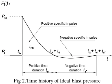
Fig 2.Time history of Ideal blast pressure
C. IDEAL BLAST WAVE CHARACTERISTICS
The above figure shows the idealized pressure profile of the blast in relation to time that occur in the medium of a free air, in the above figure it clearly mentioned that initially the pressure surrounding the element is equal to the ambient pressure PO (atmospheric pressure), when the detonation happens the release of energy in the form of heat and pressure then the surrounding ambient pressure increases instantaneously to a peak pressure PSO, this increase in the pressure takes place in the time period of tA . The peak pressure will not release at an instance, the energy and pressure releases at low rate at initial time period and it reaches peak value over the time. The time taken by the pressure to reach its ultimate value is very small and for that reason for design purposes it is considered as equal to zero.
The peak pressure Pso is also known as peak over pressure or side-on overpressure. As the wave propagates further distance from the detonation center, the velocity of propagated shock wave and the peak overpressure value will decrease. When the wave reaches its peak pressure value, the pressure starts decreasing with an exponential rate until it reaches the atmospheric pressure at a time period tA+ tO, This duration of time taken by wave reach the ambient pressure from the peak over pressure is called the positive phase duration.
After the wave reaches to ambient pressure from the peak over pressure as shown in the pressure-time diagram, the pressure still continues to drop and becomes smaller (referred to as negative) than the ambient value, as shown in the figure. This drop of pressure below the atmosphere is happened due to the wave front that takes the air in the medium along with the fronts and creates the vacuum behind the front, in this process the pressure starts to fall below the ambient pressure. But the pressure don’t meet with vacuum value i.e., zero pressure, in the process of pressure fall before it reaches the zero, the surrounding air of the blast zone will move to the low pressure area and again make the pressure equal to the atmospheric pressure finally the pressure will become ambient again. The negative phase time duration is longer than the positive phase time duration, the negative phase pressure value is denoted as Pso- and negative phase duration denoted as tO-. During this negative phase of blast propagation the structures are subjected to suction forces, this is the reason behind the
glass fragments from
outside the structure instead of in its interior.
The negative phase pressure of the explosive is not taken into account for design purposes as its value is below the ambient pressure and it has been verified that the damage to the structure is due to the positive phase. Additionally, the blast pressures that are result of the negative phase are relatively small compared to those of the positive phase blast
D. SCALING LAWS:
The most important parameter in blast load calculation is the distance of the point of detonation from the structure of interest. The velocity and peak pressure value of the blast wave, which were discussed earlier. It clear from above discussions as, increase in the distance between point of detonation and point of interest leads to decrease in peak over pressure and velocity of wave.
E. EXPLOSION AND BLAST-LOADING TYPES
The explosions are broadly classified based on the opening in the structure as
Confined explosion Unconfined explosion Dust explosion
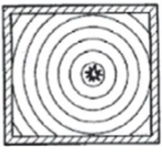
[image:3.595.322.528.77.208.2]i. Confined explosion: The explosion occurs within a building or in closed area. These are most common and results to the damage to the building and causes injury to the building inhabitants
Fig 3.confined explosions in a closed area
ii.Unconfined explosion: If the explosion occurs within the structure with some openings or in open area. The lpg cylinder blast falls under this category. Initially the gas is released in to the surrounding area and mixed with available oxygen whenever it got contact with any source of the energy like spark or fire it will explode.
Fig 4. Unconfined explosions
iii Dust explosion: A dustexplosion is the rapid combustion of very fine micron size particles suspended in air medium inside a closed environment. Dustexplosions can occur when there is combustible suspended power in the medium with higher concentration in the surrounding environment it may be other oxidizing gaseous medium like pure oxygen or hydrogen.
In this particular thesis a noncontact and unconfined explosion is considered. This unconfined explosion is considered as it has occurred outside the structure. This explosion will further classified as 3 types based on the location of the explosion material.
Free-air bursts Air bursts Surface bursts
iv. Free-air bursts:the spherical blast wave propagates from the detonation point which is at a height H. the wave front impacts directly the building without interacting with the obstacles in its travelling path.
v. Air bursts::the spherical blast wave propagates from the detonation point which is at a height H. the wave front will not impacts directly the building first it interact with ground and get reflected. It leads to create of the Mach wave front.
[image:3.595.87.250.390.543.2]Fig 5.Types of external explosions and blast loadings
III. METHODOLOGYOFANALYSIS
This chapter deals with the framework and methodology of the analysis program including the blast load calculation methods and finite element analysis software methodology of analysis. The blast pressure is calculated for different charge weight (TNT Equivalent) for different standoff distances. By observing the displacement of structural elements like columns, beams and shear walls.
The blast load is calculated based on the IS4991-1968 recommendations.
Scaled distance =
From the table 1 of IS4991-1968 for the calculated Pso, Pro, qo and to, td values for the ambient pressure pa=1 will calculate. This calculated blast load will apply on the structural elements like column and shear wall in Abaqus software with the different standoff distances like 10M, 15M, 20M, 25M, 30M, 35M and different charge weights 0.1T, 0.2T, 1T . This calculated load will apply on different grade of column like M25, M40. By using above calculated data the nonlinear dynamic analysis done on finite element software package Abaqus.
IV. ANALYSISANDCALCULATIONS Column details:
Column size:230mmx450mmx2900mm Main Bar diameter: 12mm
No of bars: 4
Stirrup diameter: 8mm
Shear wall details:
Size: 2000mmx230mmx2900mm Main Bar diameter:12
No of bars: 22
Stirrup diameter: 8mm Stirrup spacing: 290mm
[image:4.595.308.547.149.414.2]A. BLAST PARAMETERS:
Table-1:Blast Pressure and Time
Charge weight-0.1Tonne Distance
(Meter)
Pso Pro M td
Milli
Seconds
10 3.19 12.38 1.93 4.44
15 1.26 3.68 1.44 7.44
20 0.73 1.89 1.27 9.54
25 0.49 1.17 1.19 11.38
30 0.36 0.82 1.15 13.07
35 0.28 0.62 1.11 14.23
Charge weight-0.2Tonne
10 5.99 28.80 2.47 3.85
15 2.10 7.14 1.67 7.17
20 1.13 3.21 1.40 9.86
25 0.74 1.92 1.27 11.95
30 0.53 1.28 1.20 13.86
35 0.40 0.90 1.16 15.54
Charge weight-1Tonne
20 3.87 16.13 2.07 8.61
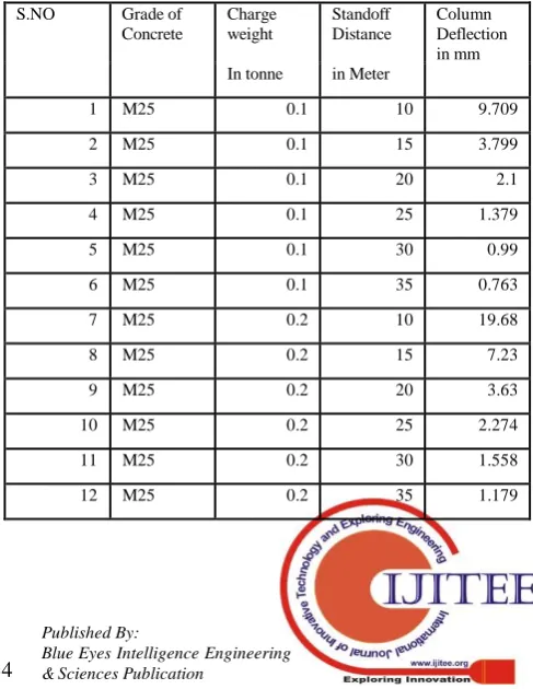
By considering above calculated blast load values and time period of positive phase of the impulse as a triangular load and analyzing the structural elements as the time history function to get the maximum deflection values at then mid-point of column in Milli-meters. The deflection values are tabulated below.
Table-2:Deflection of column at mid-point
S.NO Grade of
Concrete
Charge weight
Standoff Distance
Column Deflection in mm In tonne in Meter
1 M25 0.1 10 9.709
2 M25 0.1 15 3.799
3 M25 0.1 20 2.1
4 M25 0.1 25 1.379
5 M25 0.1 30 0.99
6 M25 0.1 35 0.763
7 M25 0.2 10 19.68
8 M25 0.2 15 7.23
9 M25 0.2 20 3.63
10 M25 0.2 25 2.274
11 M25 0.2 30 1.558
[image:4.595.302.546.519.834.2]13 M40 0.1 10 8.348
14 M40 0.1 20 1.737
15 M40 0.1 30 0.814
16 M40 0.2 10 17.59
17 M40 0.2 20 2.724
18 M40 0.2 30 1.283
19 M25 1 20 17.41
20 M40 1 20 14.43
For shear wall
21 M25 1 20 54.41
22 M40 1 20 47.91
V. RESULTSANDDISCUSSIONS
A Reinforced cement concrete column of height 2.9 meters are considered from g+2 storey building with dimensions 230mm*450mm is adopted for this study. For different standoff distances as discussed in chapter-5 the parameters considered were the concrete strength 40Mpa for high strength column and 25Mpa for normal strength column with 4 numbers of 12mm diameter main reinforcement bars and with 8 mm diameter stirrup spacing 290mm center to center. The column is modeled in abaqus software with the above configuration and analyzed.
The lateral deflection at mid-point of the column against time due to blast load is observed for different standoff distances and with different characteristic compressive strength of concrete (M25and M40) are tabulated below.
Table-3:Comparison of Deflection for different concrete grades
Member Distanc e (Meters)
Charge Weight (tonne)
Deflection (mm)
M25 grade
M40 grade
Column 10 0.1 9.709 8.348
Column 20 0.1 2.10 1.737
Column 30 0.1 0.99 0.814
Column 10 0.2 19.68 17.59
Column 20 0.2 3.63 2.724
Column 30 0.2 1.558 1.283
Column 20 1 17.41 14.43
Shear wall
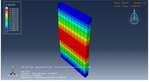
[image:5.595.44.290.48.245.2]20 1 54.41 47.91
[image:5.595.306.551.49.201.2]Fig 6.Deflection-Time history of column at Standoff distance 10m and 0.1Tonne charge weight
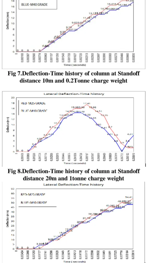
Fig 7.Deflection-Time history of column at Standoff distance 10m and 0.2Tonne charge weight
Fig 8.Deflection-Time history of column at Standoff distance 20m and 1tonne charge weight
[image:5.595.303.549.270.708.2]It is clear from the above figures and values that the grade of the concrete plays important role. The maximum lateral displacement for M25 grade columns and shear wall are always higher than the M40 grade columns and shear walls. Not only has the grade of concrete played an important role against blast but also the shear reinforcement. But now days even the 4 storey building is designing with earth quake resistance configurations as per the Indian Code IS 13920 (Ductile detailing). The detailing as per the IS13920 is enough to withstand the buildup shear in the elements. But the surface damage and distortion should prevent through high grade concrete by resisting the stresses developed in the concrete
Fig 11.Lateral Deflection of column model due to blast load
Fig 12.Lateral Deflection of shear wall model due to blast load
VI. CONCLUSION
By considering the data and literatures available in the previous studies the ultimate goal is to provide precise methodology for blast load calculation on structures and on its elements like column, beam and shear walls. It is clear that the blast pressure creates high strain rates in concrete and in steel reinforcement.in this particular thesis understanding the response of reinforced concrete column and shear wall under blast loads.
The below observations and conclusions are made from this study
1. The column subject to non-uniform blast loads leads to higher vibration modes as compared to the conventional static and dynamic loads.
2. The strength comparison between M20 grade column and M40 grade column clearly showed that the critical impulses for higher grade concretes elements are higher than lower grade concrete elements. This is due to increase in stiffness of high grade concrete. 3. Though the column is strengthened against blast load by providing the higher grade concrete, but the surface of the structure and structural elements exposed to direct blast load cannot be protected. However it can be protected by designing the sacrificial walls and by increasing the standoff distance from the point of detonation
4. The FEM analysis revealed that, for every structural element a critical blast impulse is exist. Any blast with higher impulse value than critical blast value will leads to sudden collapse of the structure before the allowable deflection and stress criterion reached.
For important building like public buildings and commercial buildings, the design considerations for blast loading should adopt to maintain the structure in life safety stage than in collapse prevention stage. It is strongly recommended that guidelines for abnormal load cases like impact loads and blast loads should be included in current building regulations and design codes.
REFERENCES
1. A.K. Pandey (2006), “Non-linear response of reinforced concrete containment structures under blast loading” nuclear engineering and design 236.pp.993-1002
2. M.V. Dharaneepathy(1995) “Effects of the stand-off distance on tall shells of different heights”. Vol.54, No.4pp.587-595.
3. B. Patil Vijay: “Effect of Blast Load on Soft Storey Building”. Vol.3 (3) pp.456-461.
4. Amol B.Unde ,Dr.S.C.Potnis(2013): “ Blast Analysis of Structure”. Vol.2 Issue7.IJERT
5. Charan.L(2018): “The study of effect of blast load on multi storey building by using time history method” Vol.5 Issue6.IRJET
6. T.Borvik(2009) “ Response of structures to planar blast loads- A finite element engineering approach”.
7. Kirk A. Marchand, FaridAlfawakhiri(2005), “Blast and Progressive collapse”. Facts For Steel Building USA.
8. J. M. Dewey (1971), “The properties of blast waves obtained from an analysis of the particle trajectories”. Proc. R. Soc. Lond. A.314,PP. 275-299
AUTHORS PROFILE
Jainu Karthik, received B.Tech from GIET Engineering College, Rajahmundry. Presently pursing M.Tech at Godavari Institute of Engineering and Technology (Autonomous), Rajahmundry.
Dr.D. Venkateswarlu, received B.Tech in Civil Engineering in the year 1991, M.Tech from IIT-KGP in Marine Structures and Ph.D from JNTUK.
[image:6.595.46.293.408.544.2]