International Journal of Innovative Technology and Exploring Engineering (IJITEE) ISSN: 2278-3075, Volume-8 Issue-12, October 2019
Abstract: This article given a second generation current controlled current conveyor positive (CCCII+), second generation current controlled current conveyor negative (CCCII-), Quadrature oscillator with high-Q frequency choosing network and implementing completely different phase oscillators by employing (CCCII+) positive and (CCCII-) negative, and high band pass filter network, the approach is predicted on the CMOS technology . The root of this concept is, considering a customary voltage mode oscillator which consists of band pass filter with prime quality issue (high-Q) and voltage mode amplifier is transfigure into current mode oscillator by replacing tans-conductance amplifier. Because the loop of the oscillator is has lavish selectivity, the oscillator process less distortion. In addition 3dB bandwidth, oscillating condition, oscillation frequency of the oscillator could linearly, independently and electronically be tuned by adjusting the bias current of the (CCCII±)[1], lastly different simulations have been carried out to verify the linearity between output and input ports, range of frequency operations. These results can justify that the designed circuits are workable.
Keywords:CCCII+, CCCII-, ALC
I. INTRODUCTION
I
n the recent years, there has been a notable demand for chip driven VLSI products in electronics, medical electronics, communications, aero space computers etc. In the analog VLSI design field, second generation current controlled current conveyor (CCCII+) positive, (CCCII-) negative have established their own identity as an salient circuit design element and getting consequential recognition in current analog IC’s design due to their higher band width , larger dynamic range, greater linearity , lower power consumption, simpler circuitry and less chip area[1]. In voltage mode to design oscillators we need BPF and voltage mode amplifier for this op-amp is used as an voltage amplifier. The op-amp experience to low slew rate at its output and less gain bandwidth product, so they remains deplorable at high frequencies.Fabre first introduced CCCII in bipolar technology[2]. Since then different CCCII based active devices have been evolve [3-8]. Like current controlled current conveyor trans conductance amplifier(CCCCTA), current controlled current differencing buffered amplifier, current controlled current differing trans conductance amplifier, current backward
Revised Manuscript Received on October 05, 2019.
G. Appala Naidu, Department of ECE,UCEV, JNTUK,
Vizianagaram-535003.
S. Mounika, Department of ECE,UCEV, JNTUK,
Vizianagaram-535003.
B.T.Krishna, Professor and Head of the Department of ECE, UCEK,
JNTUK, Kakinada-53300
trans conductance amplifier, current follower trans conductance amplifier(CFTA), current through trans conductance amplifier(CTTA) etc. [9-12] this implies that
second generation current controlled current
conveyor(CCCII) as operational trans conductance amplifier(OTA) which is a basic, general and flexible current mode device. The Current conveyors has been widely used in the realisation of analog filters, oscillators, and gyrator circuits[13-33]. Miserably, most of the oscillator design using CCCII do not satisfy high-Q frequency selecting network Then they have poor selectivity, producing more distortion. Although the oscillator in [13] employs only four CCCIIs and two grounded capacitor , the terminal z of the CCCII2 in the circuit is on the ground.
The primary intention of this article is to make use of CMOS technology and design CCCII+/- and then using CCCII+/- and high band pass filter is presented to experience low distortion signal and 3db bandwidth, linearity, oscillating condition and oscillating frequency by adjusting
bias current . and implementing
multiphase oscillators with CCCII’s.
II. DESCRIPTIONOFCCCII
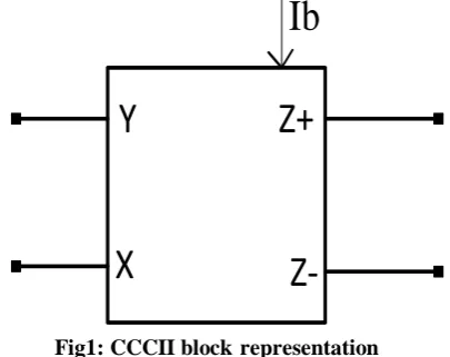
Figure (1) block representation of second generation current controlled current conveyor(CCCII). It provides electronic tunability and wide tunable range of resistance at X-terminal for either positive or negative block [34]. Thereby it no need any external resistance, therefore it is much more suitable in the design of oscillators and integrate filters. The CCCII based circuits are more suitable for high frequencies because of its current source nature. These features was very attractive to circuits designers [35].
Y
X
Z+
Z-Ib
Fig1: CCCII block representation
The correspondence between the voltage and current variable at input and output ports X, Y, Z of CCCII can be expressed by the fallowing matrix [a]
Implementation of RC Oscillator with High-Q
Frequency Selection using CCCII.
[image:1.595.329.532.566.726.2](1)
Where the ± sign reefers to plus or minus mode of CCCII respectively [1] and at X terminal Rx implies the intrinsic resistance is adjustable by supplied bias current . This can given through a trans-linear loop of class AB, which represent as input section.
(2)
(3)
(4)
Resistance at X is given as
(6)
Where is thermal voltage ≈ 26mv at c and is the bias current of CCCII [mf].
III. IMPLEMENTATIONOFCCCIIUSINGCMOS TECHNOLOGY
Figure(3) and figure(4) shows the common CMOS implementation of positive and negative current controlled
current conveyor (CCCII+, CCCII-) schematics
representation. We already perceive that metal oxide semiconductor transistors (MOS transistor) are best worthy to processing current rather than voltage type. Because of both common gate amplifier and common source configurations the current is represented as the output signal. Because of bulk-effect present in conventional CMOS process, at low supply voltage common drain amplifier configurations are ineffective. Furthermore, compare to bipolar current mirror which limits the accuracy because of the latter’s base current. The MOS current mirrors are less sensitive to process the variations and more accurate, so metal oxide semiconductor-transistor circuits could be easier to do by using current signal than voltage signals. If the saturation region operation is assumed for devices the voltages in MOS transistor schematic are proportional to the square root of the signals when a signal is delivered as current [36,37]. Consequently, a concentrate of voltage signal swing and decrease of supply voltage is possible. The maximum useable frequency will reaches soon with high values for the drain current of the MOS transistor.
The schematic of figure(2) made up of PMOS and NMOS transistors. Mp1, Mp2, Mp3, Mp4, Mp5 & Mp6 are PMOS transistors and Mn1, Mn2, Mn3, Mn4, Mn5, Mn6 & Mn7 are NMOS transistors which consists of one mixed translinear loop i.e. Mn1, Mn2, Mp5 & Mp6 acts as input cell, and two current mirrors i.e. Mp1, Mp2 and Mn3, Mn5 allows the mixed loop to be dc biased by the current ,
Y
X Z+
Mp1
Mp2 Mp3 Mp4
Mn1 Mn2
Mp5 Mp6
Mn3
Mn4
Mn5
Mn6
Mn7 VDD
VSS
Ib
Fig2: CMOS based CCCII+.
The input cell consists of low impedance output port (X) and a high input impedance output port (Y). this mixed translinear loop cell act as a voltage follower. The current flowing across port X that copies by the output Z is conceive in the conventional manner using two complementary mirrors [35].
Y
X Mp1
Mp2 Mp3
Mp4
Mn1 Mn2
Mp5 Mp6
Mn3 Mn4
Mn5
Mn6
Mn7 VDD
VSS
Mn8
Mn9 Mn7
Mn8
Z-
Ib
Fig3: CMOS based CCCII-.
IV. PROPOUNDOSCILLATOR
IMPLEMENTATION
International Journal of Innovative Technology and Exploring Engineering (IJITEE) ISSN: 2278-3075, Volume-8 Issue-12, October 2019
Av
BPF
[image:3.595.89.254.48.358.2]Vi Vo
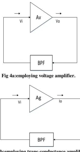
Fig 4a:employing voltage amplifier.
Ag
BPF
Vi Io
Fig 4b:employing trans-conductance amplifier.
= 0 (7)
(8)
Here,
is oscillating frequency.
In figure 4a ,
- Voltage gain.
In figure 4b ,
- trans conductance gain
.
The oscillating condition is
(9)
(10)
Here, BW is the 3dB bandwidth of the band pass network, F is the scale factor. The band pass network may be LC network, RC network, RLC network. In this work we choose RC network such as, Twin T oscillator, wein bridge oscillator, which are best example of employing an RC band pass network.
The 3dB bandwidth which, governs selectivity is
(11)
Produce more distortion signal due to the circuit is having poor selectivity because of centre frequency is twicer than that of bandwidth; so that poor filtering carried out by the band pass network , yet the band pass network employs an RC network which is active type. The BP network can filtered if any distortion introduced by amplifier and bandwidth also quite narrow in nature, Figure 5 represents
the propound oscillator with high-Q band pass network employing CCCIIs where CCCII 4 block serve as trans conductance amplifier, whose gain given as
(12)
Where block 1, 2, 3 of CCCIIs along with capacitors C1 and C2 form a feed back network then the transfer function can presented as fallows
,
(13)
As long as is set to low value can achieve the high-Q frequency selecting network
The characteristic equation is
(14)
The oscillating condition is
(15) The oscillating frequency is
(16)
Then 3dB bandwidth is
(17)
Equation (13) and figure(6) are combined for steady state sine signals to achieve the fallowing transfer function
,
(18)
From this we can say that two sinusoidal signals with equal magnitude and phase difference of is achieved. The oscillator generally implemented with
and and considering
(19)
Rationalize as,
(20)
(21)
(22)
Here
(23) The oscillator calibrate as fallows:
(a) To assure lower bandwidth adjust at block 3 i.e. CCCII3.
(b) To achieve the desired value of vary the oscillating frequency by adjusting .
[image:3.595.295.551.57.593.2]Y
Ib
X
Z
Y
Ib
X
Z
Y
Ib
X
Z
Y
Ib
X
Z
Io1
C2
Io2
C1
CCCII+
CCCII+
B1 B2
B3 B4
Fig5: propound oscillator with high-Q band pass filter, employing CCCCIIs
V. AUTOMATICLEVELCONTROL
It scrutiny that the oscillating frequency and oscillating condition can be independently tuned by adjusting the bias current and and to satisfy the bandwidth to absolutely narrow. It can possible by adjusting at block3 i.e. CCCII3. To attain constant oscillations amplitude and low distortion for variable oscillators design, the Automatic Level Control (ALC) is extensively used[34-42]. The usual ALC circuit has been enclosed in figure6 that may be a changed counterpart of the CCCII block3 in figure5 and employs a straight forward diode resistor network to control the effective price of connected to the terminal X .
±0.5V bias offer makes 2 diodes. D1 & D2 in an exceedingly weak conducting state. D1 conducts and D2 shuts once the positive 0.5 cycle initially appears; D1 shuts and D2 conducts, once the negative
0.5 cycle appears. Also is choosen deliberately high (500µA) to confirm that the parasitic electrical phenomenon of the CCCII block3 is far beyond and it will so be neglected.
This means that the CCCII block 3 is employed as a CCII3, the G3; . At the start of the oscillation, R2 has no impact as a result of he diodes are off. We tend to so have R1= 1k ohm . let = 14µA, then G4 =1.08ms, indicating oscillating condition has stopped. However, before
International Journal of Innovative Technology and Exploring Engineering (IJITEE) ISSN: 2278-3075, Volume-8 Issue-12, October 2019
Y
Ib
X
Z
Y
Ib
X
Z
Y
Ib
X
Z
Y
Ib
X
Z
D1 D2
-0.5V
0.5V R1
R2
B1 B2
B3 B4
CCCII+
CCCII+ CCCII
CCCII
-C1 Io2
[image:5.595.308.546.511.689.2]Io1 C2
Fig 6: Quadrature oscillator using ALC circuit, taking R1=1Kohm, R2=1K ohm and D1 and D2 are IN4148.
VI. COMPUTERSIMULATIONVERIFICATION
The circuits shown in Fig 2,3,5 & 6 has been simulated. The sub-circuit for the CCCII was created by the semiconductor device model of CMOS technology of the analogue device library from metallic element MULTISIM 13.0 software[39]. Then the circuit in fig.6 was simulated with ± pair of 0.5V power provides. Set C1=C2=1nF, G1=G2, particularly IB1=IB2=IB = 40.8µA. In theory, once IB4=14 µA, IB3=0.5mA. the G4=1.08ms > G3= Geq = 1ms. Then the circuit would oscillate. However, in follow once IB4 ≥ 16µA, the circuit might sustain oscillation result shown in fig 9 indicates that the particular price for fo is 498 k hz. To prove the soundness of the circuit in Fig6 Mote Carlo analysis and transient analysis for the output Io1 square measure performed with 5% tolerance of capacitances. The result illustrated in fig11. Indicates that the capacitance might slightly have an effect on the oscillating condition.
Fig8: transient response for CCCII- block
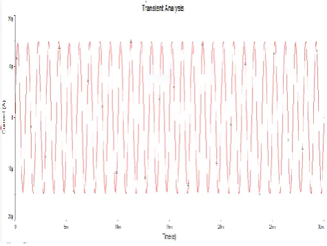
Fig9: transient response of oscillator for the design value of 0.5MHz.
Fig10: transient response for Io1 where fo dependence on IB.
Fig11: Monte-carlo analysis for design value of 0.5MHz
Fig12: output spectrum of Io1 for the design value of 1 MHz
when IB is tuned from 40.8 to 81.6 micro amps and IB4=18µA, whereas others stay unchanged, the designed value for fo is Changed from 500kHz to 1MHz which is shown in fig10, indicates that the simulated value for fo by adjusting IB.
[image:6.595.328.536.502.665.2]Fig13: Lissagous figure formed by Io1 and Io2.
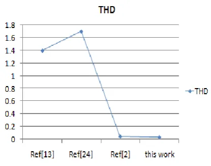
Fig 14: Comparison of Total Harmonic Distortion for different oscillators.
Since the propound circuit relies on the Bipolar Junction Transistor (BJT), a transient analysis for various various IB values.For the planning worth values of 1MHz, the frequency response of the
International Journal of Innovative Technology and Exploring Engineering (IJITEE) ISSN: 2278-3075, Volume-8 Issue-12, October 2019
the simulated lissagous figure shown in fig 13 indicates that oscillator will offer two phase current outputs with equal amplitude . the entire harmonic distortion for simulated output spectrum for Io1 , Io1 and Io2 are 0.021% . figure 12 that is very below the reported oscillators [40-48], as shown in TABLE ONE . consequently the osc generator will sustain 2 outputs with little distortion.It goes will not saying that the output of circuit simulations are in agreement with practical analysis.
Table1: comparison of characteristics different Quadrature oscillators.
Ref Basic
block
No of blocks
Passive components
ALC Capacitor
grounded
Used Used Circuit
used
yes
[13] CCCII 4 0+2 no
[24] CCCII 1 1+2 no yes
[2] CCCII 4 1+2 no yes
present CCCII 4 0+2 no yes
work
VII. CONCLUSION
As much as we all know, ther are alternative measurements strategies of getting RC oscillators. However, this study Emphasizes the utilization of high-Q frequency-selecting network and therefore the ALC circuit to get the Quadrature Oscillator with tiny distortion. In contrast to the generator proposed by Bhaskar et al. p[13]. The parasitic electrical phenomenon of the CCCII in our oscillator is a smaller amount susceptible to the result of alternative parasitic admittances since the terminal X of every CCCII is on the ground.
Therefore, the accuracy of the oscillation frequency is comparatively high electrical phenomenon characteristics of the CCCII. Finally, the final given circuit may be a Quadrature type oscillator with ALC unit, giving rise to terribly tiny distortion outputs.
Additionally, the derived oscillator conjointly enjoys the subsequent features:
(a) Linear, freelance, and electronic management of the oscillation frequency,
the oscillation condition, and therefore the 3 dB information measure.
(b) use of grounded capacitors. (c) High output impedances.
The computer simulation results agree with the implemented method.
REFERENCES
1. International academic and research project & Innovation 5(7) 2011, scholar.waset.org/1307-6892/6313, “current controlled current conveyor (CCCII) and Application mistreatment 65nm CMOS Technology”, Zia Abbas, Giuseppe Scotti and Mauro Olivieri
2. RC oscillators supported high-Q frequency choosing network “,Yong An
Li, doi: 10.1049/iet-cds.2017.0232, IET Circuits Devices Syst., 2018, Vol. 12 Iss. 1, pp. 82-87
3. Siripruchyanun, M., Jaikla, W.: ‘Current controlled current conveyor
transconductance electronic equipment (CCCCTA): a building block for analog signal processing’, Electr. Eng., 2008, 90, (6), pp. 443–453
4. Li, Y.A.: ‘NAM enlargement technique for systematic synthesis of
floating gyrators mistreatment CCCCTAs’, Analog Integr. Circuits Signal method., 2015, 82, (3), pp. 733–743
5. Summart, S., Thongsopa, C., Jaikla, W.: ‘OTA primarily based
current-mode curved construction generator with non-interactive control’, Prz. Elektrotech., 2012, 88, (7a), pp. 14–18
6. Siripruchyanun, M., Jaikla, W.: ‘Cascadable current-mode biquad filter
and quadrature generator victimization DO-CCCIIs and OTA’, Circuits Syst. Signal method., 2009, 28, (21), pp. 99–110
7. Siripruchyanun, M., Jaikla, W.: ‘CMOS current-controlled current
differencing transconductance electronic equipment and applications to analog signal processing’, AEU Int. J. Electron. Commun., 2008, 62, (4), pp. 277–287
8. Li, Y.A.: ‘Modeling, synthesis, analysis, and simulation of CCCⅡ-based
floating gyrators’, Analog Integr. Circuits Signal method., 2016, 88, (3), pp.443–453
9. Sagbas, M., Herencsar, N., Minaei, S., et al.: ‘Current and voltage mode
point in time curved oscillators victimization CBTAs’, Radioengineering, 2013, 22, (1), pp. 24–33
10. Göknar, C., Yıldız, M., Minaei, S.: ‘Metamutator applications: a
construction MOS solely generator and transconductance/transimpedance amplifiers’, Analog Integr. Circuits Signal method., 2016, 89, (3), pp. 801–808
11. Minaei, S, Cicekoglu, O.: ‘New current-mode planimeter and all-pass section
12. without external passive parts and their application to style a dual-mode
quadrature oscillator’, Frequenz, 2003, 57, (1–2), pp. 19–24
13. expedition, L., Minaei, S.: ‘A low-tension low-power resistor-based
current mirror and its applications’, J. Circuits Syst. Comput., 2017, 26, (11), p. 1750180
14. Bhaskar, D.R., Prasad, D., Senani, R., et al.: ‘New fully-uncoupled currentcontrolled sinusoidal generator using grounded capacitors’, Am. J. Electr.Electron. Eng., 2016, 4, (3), pp. 81–84
15. Bhaskar, D.R., Gupta, S.S., Senani, R., et al.: ‘New CFOA-based curved
oscillators holding freelance management of oscillation frequency even beneath the influence of parasitic impedances’, Analog Integr. Circuits Signal method., 2012, 73, (1), pp. 427–437
16. Kiranon, W., Kesorn, J., Sangpisit, W., et al.: ‘Electronically tunable multifunctional translinear-C filter and oscillator’, Electron. Lett., 1997, 33,(7), pp. 573–574
17. Abuelma'atti, M.T., Tasadduq, N.A.: ‘A novel current controlled
generator using translinear current conveyors’, Frequenz, 1998, 52, (5–6), pp. 123–124
18. Abuelma'atti, M.T., Al-Qahtani, M.A.: ‘A new current controlled point
sinusoidal generator victimization 2 translinear conveyors’, IEEE Trans. Circuits Syst. II, Analog Digit. Signal method., 1998, 45, (7), pp. 881–885
19. Horng, J.W.: ‘A curved generator victimization current-controlled
currentconveyors’, Int. J. Electron., 2001, 88, (6), pp. 659–664
20. Fongsamut, C., Anuntahirunrat, K., Kumwachara, K., et al.:
‘Currentconveyor-based single-element-controlled and current-controlled curved oscillators’, Int. J. Electron., 2006, 93, (7), pp. 467–478
21. Maheshwari, S.: ‘Current-mode third-order construction oscillator’, IET
Circuits Devices Syst., 2010, 4, (3), pp. 188–195
22. Senani, R., Bhaskar, D.R., Singh, A.K.: ‘Current conveyors: variants, applications and hardware implementations’ (Springer International publication, European country, 2015), Ch. 8, pp. 395–423
23. Senani, R., Bhaskar, D.R., Singh, A.K.: ‘Sinusoidal oscillators and wave
generators mistreatment fashionable electronic circuit building blocks’ (Springer International publication, European country, 2016), Ch. 8, pp. 395–425
24. Li, Y.A.: ‘Systematic synthesis of high-Q T-T filters using CCCIIs’, J.Circuits Syst. Comput., 2017, 26, (6), p. 1750088
25. asin, M.Y., Gopal, B.: ‘High frequency generator style employing a single
forty five nm CMOS current controlled current conveyor (CCCII+) with minimum passive components’, Circuits Syst., 2011, 2, (2), pp. 53–59
26. Skotis, G.D., Psychalinos, C.: ‘Multiphase curved oscillators
mistreatment second generation current conveyors’, AEU Int. J. Electron. Commun., 2010, 64,(12), pp. 1178–1181
27. ]Ranjan, A., Ghosh, M., Paul, S.K.: ‘Third-order voltage-mode active-C
band pass filter’, Int. J. Electron., 2015, 102, (5), pp. 781–791
28. Kumngern, M., Jongchanachavawat, W., Dejhan, K.: ‘New electronically
tunable current-mode universal biquad filter mistreatment translinear
current conveyors’, Int. J.
Electron., 2010, 97, (5), pp. 511–523
29. Fani, R., Farshidi, E.: ‘New
approach of active filters using multiple output current controlled conveyors’, IET Circuits Devices Syst., 2013, 7, (6), pp. 326–336
30. Pandey, N., Paul, S.K.: ‘A novel electronically tunable curved generator
based on CCCII (-IR)’, J. Act. Passive negatron. Devices, 2008, 3, (2008), pp.135–141
31. Sharma, R.K., Arora, T.S., Senani, R.: ‘On the realisation of canonic singleresistance- controlled oscillators victimization third generation current conveyors’,IET Circuits Devices Syst., 2017, 11, (1), pp. 10–20 32. Yuce, E., Minaei, S., Cicekoglu, O.: ‘Resistorless floating immittance function simulators using current controlled conveyors and a grounded capacitor’, Electr. Eng., 2006, 88, (6), pp. 519–525
33. Türköz, S., Minaei, S.: ‘A new current-controlled curving generator victimization the current controlled conveyor’, Frequenz, 2000, 54, (5–6), pp. 132–133
34. patriarch, M.A., Minaei, S., Yuce, E.: ‘All-Pass sections with high gain
opportunity’, Radioengineering, 2011, 20, (1), pp. 3–9
35. A. Fabre, O. Saaid, F. Wiest, and C. Boucheron, “Current governable
bandpass filter supported translinear conveyors,” Electron. Lett, vol. 31, pp.1727–1728, 1995.
36. Sedra, K. C. Smith, "A second generation current conveyor and its application", IEE Trans. Circuit Theory, 1970, pp. 132-134.
37. K.Smith and A. Sedra, “Microelectronic circuits,” pp. 368-569, 1999.
38. Giuseppe Ferri, Nicola C. Guerrini ’Low voltage Low power CMOS
Current Conveyors’ Kluwar educational Publications, pp. 2-12.
39. Budak, A.: ‘Passive and active network analysis and synthesis’
(Waveland Press Inc., 1991), pp. 459–483
40. ]Kumngern, M., Jongchanachavawat, W., Dejhan, K.: ‘New
electronically tunable current-mode universal biquad filter exploitation translinear current conveyors’, Int. J. Electron., 2010, 97, (5), pp. 511–523
41. Li, Y.A.: ‘A new single MCCCDTA based mostly Wien-bridge
generator with AGC’, AEU Int. J. Electron. Commun., 2012, 66, (2), pp. 153–156
42. Li, Y.A.: ‘Systematic derivation for construction oscillators exploitation CCCTAs’,Radioengineering, 2015, 24, (2), pp. 535–543
43. Li, Y.A.: ‘Derivation for current-mode Wien oscillators exploitation CCCCTAs’,Analog Integr. Circuits Signal method., 2015, 84, (3), pp. 479–490
44. Li, Y.A.: ‘A novel current-Mode polyphase curving generator
exploitation MOCDTAs’,Int. J. Electron., 2012, 99, (4), pp. 477–489 45. Li, Y.A.: ‘Electronically tunable current-mode biquadratic filter and
fourphase construction oscillator’, Microelectr. J., 2014, 45, (3), pp. 330–335
46. Biolek, D., Lahiri, A., Jaikla, W., et al.: ‘Realization of electronically tunable voltage-mode/current-mode construction curving generator exploitation ZC-CGCDBA’, Microelectr. J., 2011, 42, (10), pp. 1116–1123
47. Herencsar, N., Sotner, R., Koton, J., et al.: ‘New compact VM four-phase
oscillator using solely single z-copy VDTA and every one grounded passive elements’, Elektron. Elektrotech., 2013, 19, (10), pp. 87–90
48. Jerabek, J., Sotner, R., Vrba, K.: ‘Tunable polyphase generator
exploitation diamond transistors with voltage controlled condition of oscillation for amplitude stabilization’, Elektron. Elektrotech., 2014, 20, (1), pp. 45–48
49. Sotner, R., Jerabek, J., Herencsar, N., et al.: ‘Linearly tunable constructionoscillator derived from LC colpitts structure exploitation voltage differencing transconductance electronic equipment and adjustable current amplifier’, Analog Integr. Circuits Signal method.,
2014, 81, (1), pp. 121–136
AUTHORSPROFILE
G. Appala Naidu is currently working as an ssistant
Professor at the Department of Electronics and Communication Engineering at University College of Engineering Vizianagaram, JNTUK ,Vizianagaram, India. He completed his B.Tech and M.Tech from JNTU Hydrabad, India and pursing Ph.D in Department of Electronics and Communication Engineering at JNTUK University, Kakinada He worked at GITAM University, Visakhapatnam, India, as Assistant Professor. His areas of interest are Low power VLSI Signal Processing an Embedded systems.
Sanke Mounika – Post graduate in Systems and Signal
Processing (ECE) at JNTUK-UCEV. Btech in Electronics and Communication Engineering.
Dr. B. Tirumala Krishna is currently working as
Professor at the Department of Jawaharlal Nehru
Technological University Kakinada (JNTUK),