SUPERVISOR DECLARATION
“I hereby declare that I have read this thesis and in my opinion this report is sufficient in terms of scope and quality for the award of the degree of Bachelor of
Mechanical Engineering (Thermal-Fluids)”
Signature: ...
Supervisor: Dr. Fatimah Al-Zahrah Binti Mohd Sa’at Date: ...
STUDENT DECLARATION
“I hereby declare that the work in this report is my own except for summaries and quotations which have been duly acknowledged.”
Signature : ... Author : Nor Aishah Binti Mat Jam Date : ...
For my family
ACKNOWLEDGEMENT
I would like to express my utmost gratitude to Almighty Allah for giving me this opportunity to do my own research study first and foremost. I would also like to thank my supervisor, Dr. Fatimah Al-Zahrah Binti Mohd Sa’at for guiding me through the research. Her guidance, assistance, criticism and suggestions have been very helpful in the process of completing this research.
Not forgetting my family who has been supporting me through positive words and through their silent prayers; I would like to express to them my deepest gratitude. Thanks also to En. Salahuddin Bin Azraie, mechanical design enginner at Cohu Inc. Semiconductor Equipment Group for giving me this task to do my own final year project.
Lastly, I would also like to thank those who have helped me directly and indirectly towards the success of this research. Thank you and may God bless these humble servants.
ABSTRACT
A duct channel of a pick-and-place machine is a mechanical device that allowed air to flow in a duct channel which consists of a heater. Then, the air will flow to different outlets of the duct channel. The flow behaviour in the duct channel need to be studies especially flow behaviour at the outlets of the duct channel. A method based on SolidWork and ANSYS Fluent is introduced. Firstly, the duct channel structure in a specific pick-and-place machine is taken as the object for this study. A geometry of the duct channel was created in three-dimensional by using SolidWork. Then, a fluid-dynamic simulation was carried out by using ANSYS Fluent. A laminar incompressible fluid conditions were considered. The results showed that the temperature in the duct channel was not evenly distributed. The temperature only increased 1 K from the initial value of 233 K. The pressure at the outlets of the duct channel were reported with negative values in Pascal. This is not in agreement with the real value which was reported as 24.91 Pa. Further investigations are needed to find the reasons for this disagrement. The numerically calculated values of velocity at the outlets 1, 2, and 3 are 35.83655 m/s, 25.169065 m/s and 35.111923 m/s, respectively. The flow were found symmetry with respect to the middle line of the duct channel. Some irregularities of flow were found at the outlets due to several obstructions of flow in the channel. In the future, the duct channel design could be modified to increase the performance of the flow behaviour in the duct channel.
ABSTRAK
Saluran paip pada mesin kutip-dan-letak adalah aliran yang membenarkan pengaliran udara melalui pemanas yang terletak di dalam paip. Kemudian, udara akan mengalir keluar melalui saluran keluar yang berbeza. Kelakuan aliran dalam paip perlu dikaji terutama pada bahagian salur keluar paip. Geometri salur paip di lukis dalam bentuk tiga-dimensi dengan menggunakan SolidWork. Kemudian, simulasi untuk mengkaji pergerakan cecair diteruskan dengan menggunakan ANSYS Fluent. Keadaan aliran laminar yang tidak mampat diambil kira dalam kajian ini. Keputusan kajian menunjukkan bahawa suhu dalam saluran paip tidak disebarkan dengan seragam dan suhu hanya meningkat 1 K daripada suhu awal iaitu 233 K. Tekanan pada salur keluar paip adalah bernilai negatif pada unit paskal. Ini menunjukkan ketidaksamaan dengan nilai sebenar iaitu 24.91 Pa. Keperincian kajian perlu dijalankan untuk menkaji sebab ketidaksaaan nilai tekanan. Nilai kelajuan yang dikira secara berangka pada salur keluar paip 1, 2, dan 3 adalah bernilai 35.83655 m/s, 25.169065 m/s, dan 35.111923 m/s. Aliran dalam salur paip adalah berbentuk aliran simetri terhadap garisan tengah salur paip. Aliran pada salur keluar paip menunjukkan ketidakseragaman aliran. Ini kerana terdapat beberapa halangan aliran di dalam salur paip. Pada masa hadapan, Reka bentuk salur paip perlu diubahsuai untuk meningkatkan tahap prestasi aliran dalam salur paip.
.
LIST OF FIGURES
FIGURE. NO TITLE PAGE
1.0 (a) MATRIX, pick-and-place test handler (b) location of duct channel to be installed
3
2.8 Counterrotating secondary vortices 10 2.9 Friction characteristic in transition region
2.10 Heat transfer characteristic in transition region 12 2.11 Effect of Prandtl number on critical Reynolds
number
12
2.12 Variation of mean synergy angle with Prandtl number, Pr
13
2.13 (a) Friction factors
(b) Friction factors ratio of a dimpled channels
14
2.14 Comparison between experimental and numerical values
16
2.15 Location of the hot spot and the reattachment positions
16
2.16 Schematics diagram of porous-MCHSs 18 2.17 Ilustration of flow pattern near the inlet with
various shape of header
19
3.1 Flow chart for the CFD model 21
3.2 Duct channel model 22
3.3 Duct channel meshed model 22
4.1 Result for isometric view of velocity from XZ plane.
30
4.2 Result for velocity contour, viewed in XZ plane. 30 4.3 Results of velocity vector at (a) Outlet 1 (b)
Outlet 2 (c) Outlet 3 of duct channel.
31
4.4 Result for temperature contour in duct channel, viewed in XZ plane.
32
4.5 Result for temperature contour near a heater in duct channel.
32
4.6 Result for pressure contour, viewed in XZ plane. 33
LIST OF TABLES
TABLE. NO TITLE PAGE
3.1 Boundary condition of the simulation 26
4.1 Converge solution 28
4.2 Mesh sizing setting parameter 29 4.3 Results for static pressure in duct
channel
34
4.4 Results for total pressure in duct channel
34
CONTENTS
CHAPTER TITLE PAGE
SUPERVISOR DECLARATION i
STUDENT DECLARATION ii
DEDICATION iii
ACKNOWLEDGEMENT iv
ABSTRACT v
ABSTRAK vi
LIST OF FIGURES vii
LIST OF TABLES ix
CHAPTER 1 INTRODUCTION
1.1 1.2 1.3 1.4 Background study Problem statement Objectives Scope 1 2 3 3
CHAPTER 2 LITERATURE REVIEW
2.1 2.2 2.3 2.4 2.5 2.6 2.7 Duct channel Flow distribution
Computational Fluid dynamics Laminar flow
Turbulent flow
Steady flow and unsteady flow The effect of channel configuration
4 7 8 10 14 16 17
CHAPTER 3 METHODOLOGY
3.1 3.2 3.3 Flow chart Preprocessing Solver setting
3.3.1 Double precision 3.3.2 Governing equation 3.3.3 Natural convection 3.3.4 Viscous dissipation
20 21 23 23 23 24 25
3.4 Boundary condition 26
3.5 Post processing 3.5.1 Vorticity
3.5.2 Solution method setting
27 27 27 CHAPTER 4
4.1
DATA AND RESULTS Results
4.1.1 Converge
4.1.2 Grid Independency Test 4.1.3 Velocity 4.1.4 Vorticity 4.1.5 Temperature 4.1.6 Pressure 28 28 28 29 31 32 33
CHAPTER 5 DISCUSSION 35
CHAPTER 6 CONCLUSION/RECOMMENDATIONS 37
REFERENCES 39
APPENDIX 43
CHAPTER 1
INTRODUCTION
This chapter will explain briefly the development and purpose of the project and provide a general overview of the project. The description of the scope and planning for the project work is also given.
1.1 BACKGROUND STUDY
Duct channel of a pick-and-place machine is a mechanical device that allowed air to flow in the duct channel which consists of a heater. Figure 1.0 shows an example of the duct channel in a pick-and-place machine used at Cohu Inc. Semiconductor Equipment Group. It is located at center top of the TS environment. It has been speculated that heated air is not evenly distributed and causing condensation happened at far right and far left location of the TS environment. Therefore, advance in development of computational fluid dynamics (CFD) provide a good way to understand the flow fields distribution. This project is focus on flow behaviour in duct channel especially on the flow behaviour at the outlets. This studies will reveal the flow fields distribution inside the duct channel. Parameters related to this studies will be discussed in this project. A geometry of duct channel is created in the SolidWork. SolidWork is a three-dimensional mechanical computer-aided design program that runs on microsoft window. The flow behaviour at duct channel configuration is carried out by using computational fluid dynamics software ANSYS
Fluent. This project is to understand the flow distribution at the outlet of duct channel with hope that the study will come up with ideas of good design in future.
Figure 1.0 : (a) MATRIX,pick-and-place test handler. (b) location of duct channel to be installed at upper frame.
1.2 PROBLEM STATEMENT
The behaviour of flow plays an important role in controlling the distribution of heat inside a duct channel. The duct channel considered in this study is a mechanical device that allowed air to flow in the duct channel which consists of a heater. Then, the air will flow to different outlets of duct channel and passes into a chamber called TS environment. TS environment is a control environment for semiconductor device testing. The duct channel used for this project is a duct channel of pick-and-place machine as shows in (Figure 1.0 (a)). A pick-and-place machine is a semiconductor machine to test chips or any small devices. Temperature inside TS environment needs to be slightly above dew point in order to prevent condensation. Once condensation happened, frost will be an issue. Circulating air inside the TS environment via a duct channel system helps to maintain the temperature. Heated air
needs to be circulated evenly inside the TS environment. The current duct channel system consists of centrifugal blower as an intake and three channels as outlets. It is located at center top of the TS environment (Figure 1.0(b)). It has been speculated that heated air is not evenly distributed and causing condensation at right location and left location of the TS environment. Therefore, advance in development of computational fluid dynamics (CFD) provide a good way to understand the flow fields distribution. This project is focus on flow behaviour at duct channel especially on the flow behaviour at the outlets. This studies will reveal the flow fields distribution inside the duct channel. Parameters related to this studies will be discussed in this project
1.3 OBJECTIVE
1. To study flow distribution inside the duct channel configuration.
2. To analyze flow distribution at the outlets of the duct channel configuration. 3. To compare pressure at the outlets of the duct channel with data given by Cohu
Inc. Semiconductor Equipment Group.
1.4 SCOPE
The study is limited to one type of configurations. This project will focused on flow behaviour at the duct channel outlets. The problem will be investigated numerically using a commercial software which is ANSYS Fluent.
CHAPTER 2
LITERATURE REVIEW
This chapter presents a summary of previous relevent published works.
2.1 Duct channel
Duct channel is a pipe systems used to deliver or remove air from one place to another. Duct channel can be made out of galvanized steel, aluminium, polyurethane and phenolic insulation panels (pre-insulated air ducts), fiberglass duct board (preinsulated non-metallic ductwork), flexible ducting, fabric ducting and waterproofing. Typical materials commonly used to make up ductwork are galvanized steel and fiberglass duct board. Galvanized steel can be formed into round or rectangular shape while foil-faced fiberglass duct board can be formed into angular shapes or insulated flexible fabric round duct. Different material has different friction factors. In design process, material selection is one of the important criteria that must be considered. Material with high friction or duct length will affect the total pressure loss. The best materials for duct is galvanized steel because it has lower friction rate than flexible duct due to the smoother inside surface of the steel duct (Arlan, 2011).
Flows in close channels likes pipe and duct are closely in contact with rigid boundaries. Most channel in engineering applications are either circular or rectangular in cross sections.
An investigation of heat transfer and friction factor characteristics of a rectangular channel solar air heater duct having protusions as roughness element has been carried out by Manesh Kaushar Varun (2013). He studied the effect of protruded geometry on heat transfer coefficient and friction factor in an artificially roughened solar air heater duct. It was concluded that the friction factor and Nusselt number of roughened duct are a strong function of flow attack angle. The result was compared with smooth duct and was shown that significant increase in the heat transfer through roughened duct.
The mixed convection heat transfer around five in-line isothermal square cylinders periodically arranged within a vertical duct was studied by Chartterjee and Raja (2013). At one width of cylinder dimension, the spacing between two cylinders is fixed. The flow confinement of different degrees were studied for the blockage ratios of 0%, 10%, 25% and 50%. Simulation of two-dimensional incompressible, laminar flow and heat transfer problem were carried out by finite volume method available in a commercial software, Fluent. Other investigation in vertical duct were carried out by Yu et al. (2014). They studied orientation of cone settling in a vertical duct by using the direct-forcing fictitious domain method. They come up with a relation of Reynolds number, Re, with the orientation of cone in a vertical duct.
Rahman (2013) studied non-isothermal flow through a curved square channel with strong curvature. Numerical investigation by using a spectral method was used. The study covers a wide range of Dean number, Dn in the range 100
≤
Dn≤
6000 for the curvature δ = 0.5. Dean number is a dimensionless number giving ratio of viscous force acting on a fluid flowing in a curved pipe to the centrifugal force; equal to the Reynolds number, Re, times the square root of the ration of a radius of the pipe to its radius of curvature. The ultimate goal was to investigate the non-isothermal flow through a curved channel with the presence of bouyancy effect when the square channel has strong curvature. In previous investigation, numerical prediction of non-isothermal flow through a curved square duct over a wide range of the curvature and Dean number was performed by Mondal et al (2006). Both showed that stability characteristics drastically change due to an increase of curvature.Sediki (2009) researched about interaction of mixed convection and thermal radiation in laminar air flow inside an inclined cylindrical duct with Uniform Wall Heat Flux. The radiative double effects of water vapor in air flow on thermal and on dynamics fields was highlighted in his study. The objective was to point up the effect of water vapor radiative behaviour and the effect of the inclined angle on the evolution of temperature, velocity, Nusselt number, bulk and wall temperature. Flow equations and energy balance equation were solve simultaneously with temperature dependent thermophysical properties. An implicit finite differece technique was used to solve mass, momentum, and energy equations. Another experimental was conducted under condition of uniform wall heat flux. The work was done by Mohamad and Salman (2007). They studied mixed convection heat transfer in circular horizontal duct, vertical duct and inclined duct. The results of this investigation show that a decrease of inclination angle leads to an increase on the Nusselt number values. The average heat transfer results and Nusselt numbers were correlated with empirical correlations in terms of dependent parameters of Grashoff, GrL, Prandtl number, Pr, and Reynolds number, Re. The equation for these numbers are shown below:
2 3 L ) ( Gr v L T T
g s − ∞ c
= β
(2.1) Where g= gravitational acceleration, m/s2
β = coefficient of volume expansion, 1/K(β = 1/T for ideal gases)
s
T = temperature of the surface, °C
∞
T = temperature of fluid sufficiently far from the surface,°C
c
L = characteristic length of the geometry, m
v
= kinematic viscosity of the fluid, m2 / sk
C a
v = µ p
=
Pr
(2.2) Where
v
=
kinematic viscosity of the fluid, m2 / sα
= thermal diffusivity, m2 / s =p
µ = dynamics viscosity, Ns / m2
k
= thermal conductivity, W / (m.K)µ
ρ c
c VL
v VL = =
Re
(2.3) Where V = upstream velocity
Lc= characteristic length of the geometry, m ρ = density, kg / m3
v
= kinematic viscosity of the fluidm
2/
s
2.2 Flow distribution
Liquid or gas flow through pipes or ducts is commonly used in heating and cooling applications and fluid distribution networks. The terms pipe and duct are usually used interchangeably for flow sections. In general, flow sections or circular cross section are referred to as pipes. This is especially when the fluids is liquid. The flow sections of non-circular cross section are known as duct. Small diameter pipes are usually referred as tubes. Most liquid are often transported in circular pipes. This is because pipes with circular cross section can withstand large pressure difference between the inside and the outside without undergoing significant distortion. Besides, the non-circular pipes are also used in applications such as the heating and cooling systems of when the pressure difference is relatively small, the manufacturing and installation costs are lower, and the available space is limited for ductwork.
Martin et al. (2014) studied velocity distribution in pressurized flow using Computational Fluid Dynamics (CFD). Analysis was carried out for combination of three dimensionless mesh parameters. The three dimensionless mesh parameters are dimensionless mesh size in axial direction expressed in terms of number of diameters, λa, dimensionless mesh size in a circumferential direction expressed in terms of pipe perimeter, λc, and ratio between the first layer thickness (FLT) and the
thickness of the viscous sublayer for a specific turbulent flow, λr. A four steps systematic approach was used to obtained most efficient meshes. Three dimensionless mesh generation parameters were defined to discribe pipe geometry. Most efficient meshes were obtained for minimum error number of nodes.
Li et al. (2014) studied effect of slip distribution on flow past a circular cylinder. They examined in detail flow with fore-side slip distribution and compared results with no slip and all slip distributions. Other distribution types have also been studied. These studies established strategies for slip placement for desired flow control effects. Comparison of different slip distribution types revealed that flanks of the cylinder was the best location to implement slip for drag and lift reduction. Based on observation, rotation of the cylinder can be achieved by an asymmetric slip distribution.
2.3 Computational Fluid Dynamics
Computational fluid dynamics (CFD) is part of fluid mechanics tools for analysis that uses numerical method and algorithm to solve and analyse problem that related to fluid flow. CFD is a computer-based mathematical modelling tool that incorporates the solution of the fundamental equations of fluid flow, the Navier-Stokes equations, and other related equations. There are three stages in CFD modelling: pre-processing or creation of geometry; solve the flow equation; and post-processing such as visualization of a CFD code’s predictions.
Nowadays, CFD simulation software is widely used across the world in many sectors. Wide range of application may be simulated using CFD. This includes aerospace, nuclear and automotive sectors. In automotive sector alone, CFD may be used in the simulation related to manufacturing and chemical processes (Brenner, 2009). In the medical industry, for an example, the CFD method may be applied to the flow field related to pharmaceuticals, biomedical and electronics (Brenner, 2009). Computational fluid dynamics (CFD) technique is gradualy becoming an attractive tool for a better understanding of the flow delivery process before any future plant
optimisation is carried out. Unfortunely, in solving many complex flows, CFD analysis can only offer a qualitative rather than a quantitative prediction of flow behaviour. Based on this, majority of numerical models used in CFD were created using flow data that are often remotely representative of the real industrial flow. Therefore, model validation is essential to ensure that the numerical models are capable of solving industrial flow problems especially those that have not previously been studied by the scientific community ( Benny and Philip, (2003).
Computational fluid dynamics (CFD) solves flow and heat transfer based on Navier-Stokes equations. The Navier-Stokes equations for steady, incompressible flow are: Continuity Equation: 0 = ∂ ∂ + ∂ ∂ + ∂ ∂ z w y v x u (2.4)
Momentum equation in x-direction:
∂ ∂ + ∂ ∂ + ∂ ∂ + ∂ ∂ − = ∂ ∂ + ∂ ∂ + ∂ ∂ z w y v x v x P z w w y v v x u
u µ 22 22 22
ρ
(2.5) Momentum equation in y-direction:
∂ ∂ + ∂ ∂ + ∂ ∂ + + ∂ ∂ − = ∂ ∂ + ∂ ∂ + ∂ ∂ 2 2 2 2 z v y v x v g y P z v w y v v x v
u ρ y µ
ρ (2.6)
Energy equation (viscous dissipation is negligible)
∂ ∂ + ∂ ∂ + ∂ ∂ = ∂ ∂ + ∂ ∂ + ∂ ∂ 2 2 2 2 2 2 z T y T x T k z T w y T v x T u (2.7)
Studies of fluids flows through duct channel were investigated by many researches. The researchers on fluid flows involved laminar, turbulent, steady, unsteady flows and the effect of channel configurations were discussed in the subsequent sections.
2.4 Laminar Flow
[image:21.595.147.493.257.643.2]Facao and Armando (2005) studied fluid flow and convective heat transfer in a curved rectangular channel. The heat transfer coefficient was assessed using FLUENT code. The results show that the Nusselt number for the curved duct is up to 10 times higher than for a straight duct. This is due to counterrotating secondary vortices formation. The counterrotating secondary vortices formation is shown in Figure 2.8.
Figure 2.8 : Counterrotating secondary vortices (Facao and Armando, 2005)
Oulaid et al. (2010) studied effect of buoyancy forces on an upward, steady state, laminar flow of humid air in a vertical parallel-plate channel. The plates were wetted
by a thin liquid water film. Temperature of the plates were maintained at constant temperature which was lower than temperature of air entering the channel. A two-dimensional fully elliptical model, associated with the Boussinesq assumption, was used to take into account axial diffusion. Solution of mathematical model was based on finite volume method. Velocity-pressure coupling was handled by a SIMPLER algorithm. Influence of the gas temperature at channel entrance and mass diffussion Grashof number were studied. Numerical results showed that buoyancy forces have significant effect on the hydrodynamics, thermal and mass fraction fields. These forces induced flow reversel for high temperature and mass fraction at the channel entrance.
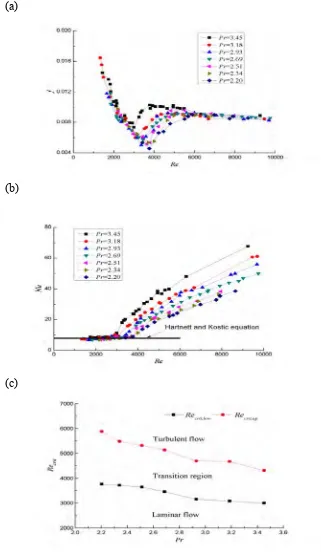
Wang et al. (2013) studied forced convection heat transfer and friction characteristics in laminar to turbulent transition region in a vertical heated rectangular channel. An experiment was designed for analyzing the effect of Prandtl number on the heat transfer and friction characteristics of the transition flow region. Seven groups of experiments were carried out within range of Reynolds number from 1000 to 2 x 10⁴ Prandtl number in each group was 2.10, 2.34, 2.51, 2.69, 2.93, 3.18, and 3.45, respectively. Results shown that lower and upper critical Reynolds number of transition region increased with the decreased of Prandtl number. The result is shown in Figure 2.9 (a). Friction factors increase with increasing Prandtl number for a fixed Reynolds number in the transition region. Figure 2.9 (a) and Figure 2.9 (b) show friction and heat transfer characteristics of flow with wall heating condition. The figure clearly showed that the Prandtl number significantly influences the friction and heat transfer characteristic in laminar and turbulent transition region.
(a)
(b)
[image:23.595.144.465.85.640.2](c)
Figure 2.9 : (a) Friction characteristics in transition region (b) Heat Transfer characteristics in transition region and (c) Effect of Prandtl number on critical
Reynolds number ( Wang et al. 2013)
Figure 2.9 (c) shows effect of Prandtl on transition critical Reynold number. Low critical reynolds number, Recrit,low and upper critical reynolds number, Recrit,up both decrease with the increase of Prandtl number ( Wang et al. 2013).
[image:24.595.188.431.333.507.2]Zhang et al. (2014) studied field synergy analysis for helical ducts with rectangular cross section. They proposed a new approach based on Vorticity-Stream function-Poisson,VSP, equation method. VSP was used to study numerically fully developed laminar flow characteristics and heat transfer behaviours of helical ducts with rectangular cross section. The aim was to guide heat transfer enhancement for helical rectangular ducts. The effect of Prandtl number, Pr, on field synergy was examined. The effect of Pr on field synergy is shown in Figure 2.12.
Figure 2.12 : Variation of mean synergy angle with Prandtl number, Pr ( Zhang et al., 2014)
Figure 2.12 shows variation of mean synergy angle with Prandtl number, Pr. As Pr increases, the mean synergy angle also increase. In the case of high Pr number, it was important to improve the field synergy to enhance heat transfer ( Zhang et al, 2014).