K. Suzuki
Geotechnical Eng. Dept., Technical Research Institute, Obayashi Corporation, Tokyo, Japan
Keywords: creep, evolution damage zone, underground opening, numerical simulation
ABSTRACT: The time-dependent mechanical and hydraulic behaviour of rock in the excavation disturbed zone (EDZ) in the vicinity of underground facilities is important for the safety assessment of these underground excavations. To simulate the evolution disturbed zone (EDZ) around a circular opening in granitic rocks under creep test (biaxial), a micromechanics-based continuum damage model (Golshani et al., 2003) is used. Then, the numerical results are compared to the experimental data from the creep test on a rectangular prism specimen of Inada granite containing a circular opening. The results of numerical simulation are in good agreement with the experimental test and indicate that the damage evolution zone mainly occurs in the side walls of the opening under biaxial creep condition.
1 Introduction
The excavation of underground openings results in a change in stress distribution and pore water pressure leading to the development of fractures. Such changes alter the mechanical rock mass properties such as strength and deformability, and the hydraulic conductivities and hence influence contaminant pathways.
Depending on mechanical host rock properties, the stress redistribution may lead to the development of a plastic zone around the tunnel, termed as excavation disturbed zone (EDZ). One of the major problems in the assessment of safety of underground facilities such as waste disposal storage is the transmissivity of the EDZ zone. In other words, the EDZ with its increased permeability constitutes a potential risk to the effectiveness of the storage in waste isolation from the accessible environment.
The failure mechanism in the EDZ zone is the initiation and growth of microcracks. To characterize the behavior of the EDZ zone, time influence on the mechanical properties of rock is of great importance. Under constant loading (creep), the microcracking occurs through two mechanisms: stress-induced microcrack growth and time dependent microcrack growth. Time dependent failure of brittle rocks under constant loading results from stable microcracks growth. This stable microcrack growth, called sub-critical crack growth, can occur even if the stress intensity factor at microcrack tip is below fracture toughness.
Analytical and numerical solution for modeling of the EDZ in the vicinity of underground excavations exists (e.g. Souley et al., 2001; Fakhimi et al., 2002; Chen et al., 2004), however, there is very little knowledge on the actual development of the EDZ starting from microcracking of intact rock around the openings under creep loading.
Simulation of damage around a circular opening in rock
A. Golshani, Y. Okui, M. Oda
Dept. of Civil Engineering, Saitama University, Saitama, Japan
Close
By drawing on this background information, this paper utilizes the micromechanics-based continuum damage model proposed by Golshani et al. (2004) to simulate the EDZ and its time-dependent development. Furthermore, numerical data will be compared to the results of a plane stress (biaxial) creep test which was performed on a rectangular sample containing a circular opening of Inada granite (from a quarry in Kasama, Ibaraki, Japan).
2 A brief review of damage model
In this model, a rock is idealized as an elastic material with N groups of microcracks. Each microcrack group is characterized by its unit vector n(i), the average microcrack length 2c(i) and the number ρ(i) of microcracks per unit area of material in group i (Number density of microcracks). It is assumed that the matrix material remains elastic during the entire loading history and all inelastic deformation is due to microcracking (brittle materials). Therefore, the stress-strain relationship is given by (e.g. Horii and Nemat-Naseer, 1983):
:
(
*)
ε
ε
σ
=
D
e t−
(1)where De is the elastic modulus tensor, εt is total strain and ε *
is inelastic strain associated with the opening of microcracks. For each group of microcracks, the inelastic starin is as a function of the number density of microcracks, microcracks length, microcracks orientation: θ(i) and the applied stress. Therefore, the total inelastic strain is given by (see for more detail, Golshani et al, 2004):
∑
=
=
Ni
i i i
c
1
) ( ) ( ) ( * *
)
,
,
,
(
ρ
θ
σ
ε
ε
(2)By assuming that microcrack growth occurs in tensile mode, the stress intensity factor KI for a
single microcrack with length of 2c and the orientation angle of θis approximated by
K
I=
π
c
σ
t′
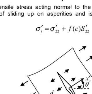
(3)where σ’t is the local tensile stress acting normal to the microcrack surface (Fig. 1), which is
generated as a result of sliding up on asperities and is expressed by (with respect to local coordinate):
σ
t′ σ
=
22′
+
f
(
c
)
S
22′
(4)
x
2x
12 xc
1 xc
T
22 )
( S
c
d c
22
[image:2.545.160.320.362.526.2]V
cFigure 1. Microcrack under local tensile stress
deviatoric stress S’22 and f(c) is a proportionality coefficient depending on only c. It should be
mentioned that microcrack growth causes the tensile stress to be relieved as the microcrack propagate. Otherwise, microcrack would propagate without any limit. Therefore, it is assumed that the f(c) is inversely proportional to the half of microcrack length;
f
(
c
)
=
d
/
c
(5) Here d is a typical length scale of material such as grain size. The microcrack growth law for stress-dependent propagation is given as follows:
K
I−
K
IC=
0
(6) In this case, microcrack grows because the stress in the region surrounding the microcrack is sufficient to cause the stress intensity factor: KI to equal the fracture toughness: KIC.On the other hand, for time-dependent microcrack growth the subcritical microcrack growth rate
dc / dt is assumed to obey a power law (Atkinson, 1984):
dc
/
dt
=
A
(
K
I/
K
IC)
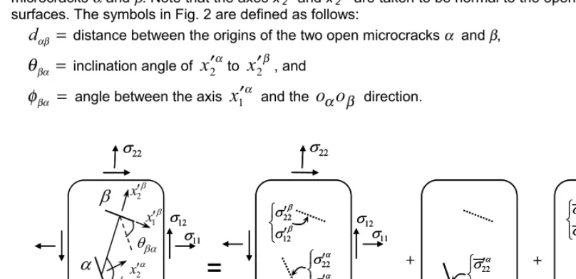
n (7) where A and n are sub-critical microcrack growth parameters which depend on the type of rock and environmental conditions.In deformation and failure of brittle materials, isolated microcrack growth occurs only at relatively low stresses. Once numerous microcracks begin to grow, interaction among them starts to play a very important role in the evolution of further microcracking. Eq. (4) was formulated by disregarding the existence of neighboring open microcracks, so that its use should be limited within the early stage of non-elastic deformation where interaction among open microcracks is not dominant. The so-called pseudo-traction method provides a powerful tool for evaluating the elastic interaction among microcracks (Horii and Nemat-Nasser, 1985a, b). To outline the principle, we first consider an infinite plate with two open (not potential) microcracks α and β of lengths 2ca and 2cβ,
respectively, which is subjected to far field stresses (Fig. 2). Two coordinate systems, x’iα and x ’ iβ
(i=1, 2), are employed such that their origins, oα and oβ, are located at the centers of the open microcracks α and β. Note that the axes x’2α and x
’
2β are taken to be normal to the open microcrack
surfaces. The symbols in Fig. 2 are defined as follows:
=
αβ
d
distance between the origins of the two open microcracks α and β,=
βα
θ
inclination angle ofx
2′
αtox
2′
β, and=
βα
φ
angle between the axisx
1′
α and theo
αo
β direction.22
V
11 V=
D
E
TED D 1 xc D 2 xc IEDx
2x
1 E 1 xc E 2 xc 22V
11 V 12V V12
¯ ® c c D D V V 12 22 ¯ ® c c D D V V 12 22 ¯ ® c c E E V V 12 22 ¯ ® c c E E V V 12 22 22
V
11 V=
D
E
TED D 1 xc D 2 xc IEDx
2x
1 E 1 xc E 2 xc 22V
11 V 12V V12
¯ ® c c D D V V 12 22 ¯ ® c c D D V V 12 22 ¯ ® c c E E V V 12 22 ¯ ® c c E E V V 12 22
[image:3.545.41.445.371.567.2](a)Original problem (b) Homogeneous subproblem (c)Subproblem D (d)Subproblem E
Our original boundary problem is decomposed into three problems; i.e., one homogenous sub-problem and two sub-sub-problems α and β (Fig. 2). In the homogenous sub-problem, there is no open microcrack and the domain is subjected to the same far field stresses, σ11, σ22 and σ12, as those in the original problem. In sub-problem α, one open microcrack α is considered in the infinite solid under zero far field stresses. The stresses
σ
22′
α andσ
12′
α are applied, as boundary stresses, on thesurface of open microcrack α. Similarly, the boundary stresses
σ
22′
β andσ
12′
β are also applied on the surface of open microcrack β in sub-problem β.The stresses must be zero on the surface of the open microcrack α in the original boundary problem. This requirement is satisfied by means of the following equalities:
σ
′
22α+
σ
22′
α+
σ
22′
Pα=
0
(8a)
12
′
+
12′
+
12′
=
0
α αα
σ
σ
σ
P(8b)
where
σ
22′
αandα
σ
12′
are the stresses at the position of microcrack α arising from the far field stressin the homogenous sub-problem, and the quantities
σ
22′
Pαandσ
12′
Pα, called the pseudo-tractions, are the stresses at the position of microcrack α in sub-problem β.The pseudo-tractions must be determined such that all the boundary conditions for the original problem are satisfied. Using Muskhelishivili’s complex stress function, we can obtain an equation called the consistency equation to ensure the traction-free condition on the surface of the open microcrack, as follows (see Okui et al., 1993):
{
σ
′
Pα}
=
[
γ
′
αβ]({
σ
′
β}
+
{
σ
′
Pβ})
(9)where
{
P}
{
11P,
22P,
12P}
T α α αα
σ
σ
σ
σ
′
=
′
′
′
,{
}
{
11,
22,
12}
T β β ββ
σ
σ
σ
σ
′
=
′
′
′
, andγ ′
αβ is a 3 by 3 matrixwhose elements are functions of the position vectors at the center of microcracks, angle between microcracks surfaces θαβ, length of the source microcrack and d. In Eq. (9) only two microcracks are
considered. In reality, however, a huge number of microcracks are distributed in the domain and the consistency equation: Eq. (9) can be generalized as an integral equation for all microcracks. Considering the effect of interaction, the stress intensity factor equation can be rewritten as follows:
(
)
+
−
+
+
+
=
2
)
(
)
(
)
(
)
,
,
(
11 11 22 2211 11
P P
P P
I
c
c
f
c
K
σ
σ
π
σ
σ
σ
σ
σ
σ
(10)Finally, the governing equations are stress-strain relationship: Eq. (1), stress-dependent microcrack growth law: Eq. (6), time-dependent microcrack growth law: Eq. (7) and consistency equation: Eq. (9). All the parameters of this model can be determined from triaxial compression tests and observation of microcracks growth under microscope.
3 Analysis of a rectangular sample containing an opening
observation under microscope. All parameters that appeared in the governing equations for Inada granite are listed in Table 1.
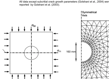
[image:5.545.83.399.145.266.2]In numerical simulations, a stress dependent analysis was performed until reaching the desired stress state and then a time dependent analysis was started. Note that confining pressure was σ11 = 10 MPa and creep stress held at σ22 = ҏ40 MPa.
Table 1. Model parameters used in numerical simulation for time dependent behavior of Inada granite.
Parameter Value(s)
Young’s modulus E = 73GPa Poisson’s ratio ν = 0.23 Length parameter [mm] d = 0.34 Fracture toughness [MPa m1/2] KIC = 2.5
Microcracks orientation Vertical Horizontal
Initial microcrack length: 2c0 [mm] 1.12 1.08
Number density of microcracks: ρ [mm-2] 0.45 0.67 Subcritical crack growth parameters n = 50 A = 2.0E-23 m/s
All data except subcritial crack growth parameters (Golshani et al., 2004) were reported by Golshani et al. (2003).
σ11 σ22
x
1x
2σ11 σ22
x
1x
2σ22
x
1x
2Symmetrical Axis
250 mm
500 mm 160 mm
Symmetrical Axis
250 mm
500 mm 160 mm
(a) (b)
[image:5.545.48.424.312.583.2]3.1 Results
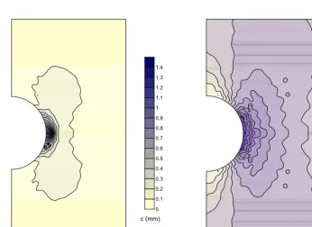
In Fig. 4 microcracks length distribution at failure point is shown. Damage evolution zone which is caused by microcracking, in side wall area is larger than the roof and floor of the opening (e.g. Chen et al. 2004). Furthermore, increased compression occurs in the side wall area (Fig. 5). It can be concluded that the regions of increased compressive stress around the opening are disturbed more (This feature has been indicated for stress-dependent damage case by Read and Chandler, 1999). Also, the damage zone is limited to less than one radius of the opening in the surrounding rock.
0 0.1 0.2 0.3 0.4 0.5 0.6 0.7 0.8 0.9 1 1.1 1.2 1.3 1.4
c (mm)
-2.6 -2.2 -1.8 -1.4 -1 -0.6 -0.2
0.2
(a) (b)
Figure 3. (a) Microcracks length distribution at failure (b) Normalized stress:
σ
11/
σ
0distribution at
failure (Note that
σ
0is the reference stress and is set to 63 MPa).
4 Experimental
model
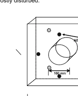
Creep test (biaxial, plane stress condition) was carried out using a rectangular prism of Inada granite containing a 16 mm diameter circular hole was tested to model time-dependent behaviour of an underground opening experimentally (Fig. 4).
The horizontal and vertical loads were applied at a rate of 10 KN/m simultaneously. When the horizontal load reached the required desired value (confining pressure equal to 10 MPa), it was stopped, while the applied vertical load increased at a constant strain rate of 0.25 mm/min. The vertical load was applied until the required value (vertical stress equal to 40 MPa) was achieved. Then, both horizontal and vertical loads were kept constant to simulate the constant stress state. Acoustic emission (AE) was used to monitor the failure process during the creep test. Eight sensors, four on each face of the specimen as shown in Fig.4, were used to monitor AE during the creep test.
Figures 5 and 6 show the location of the AE events which were recorded after 5521 seconds and 146755 seconds, respectively. It can be seen that the events were mainly concentrated around the
[image:6.545.77.424.139.391.2]mass around the opening, these events do not necessarily refer to the active microcracks which are significant in the sense of their effect on mechanical properties of rock mass such as the permeability.
5 Conclusions
The purpose of this study was to investigate numerically the damage evolution zone under creep condition around an opening in Inada granite. In this regard, a micromechanics-based continuum damage model proposed by Golshani et al. (2004) was used to simulate the evolution damage zone (EDZ) around an opening under creep condition. The results of numerical simulation are in good agreement with the experimental test. Both numerical modeling and experimental test indicate that the damage evolution zone mainly occurs in the side walls of the opening under biaxial creep condition. Also, from numerical simulation, it can be seen that the increased compression regions (around side walls) are mostly disturbed.
500 mm 160 mm
x1
x2 50
mm
AE sensors
500 mm 160 mm
x1
x2 50
mm
[image:7.545.163.298.210.377.2]AE sensors
Figure 4. Specimen geometry and AE monitoring
0 100 200 300 400 500
0 100 200 300 400 500 0 100 200 300 400 500
025 50 0 100 200 300 400 500
0 100 200 300 400 500
0 100 200 300 400 500
0 25 50
(a) (b)
[image:7.545.59.428.421.582.2]6 Acknowledgements
This work was supported partially by Japan Society for the Promotion of Science (JSPS).
7 References
Atkinson B.K. 1984. Subcritical crack growth in geological materials, Journal of Geophysical Research, 89(B6), 4077-4114. Chen W.Z., Zhu W.S., Shao J.F. 2004. Damage coupled time-dependent model of a jointed rock mass and application to large
underground cavern excavation, International Journal of Rock Mechanics and Mining Science, 41, 669-677.
Fakhimi A., Carvalho F., Ishida T., Labuz J.F. 2002. Simulation of failure around a circular opening in rock. International Journal
of Rock Mechanics and Mining Science, 39, 507-515.
Golshani A., Okui Y., Takemura T., Oda M.. 2004. Time dependent continuous damage model for brittle failure of rocks,
EUROCK 2004 & 53rd
Geomechanics Colloquium, Salzburg (Austria), 701-706.
Golshani A. 2003, A micromechanical model for brittle failure of rock under compression, Ph.D. dissertation, Civil Engineering Department, Saitama University, Saitama (Japan), 80 pages.
Horii H., Nemat-Nasser S. 1983. Overall moduli of solids with microcracks: load-induced anisotropy, J. Mech. Phys. Solids, 31(2), 155-177.
Horii H., Nemat-Nasser S. 1985a. Compression-induced microcrack growth in brittle solids: axial splitting and shear failure,
Journal of Geophysical Research, 90, 3105-3125.
Horii H,, Nemat-Nasser S. 1985b. Elastic fields of interacting inhomogeneities, Int. J. Solids Struct., 21, 731-745.
Hou Z. 2003. Mechanical and hydraulic behaviour of rock salt in the excavation disturbed zone around underground facilities,
International Journal of Rock Mechanics and Mining Science, 40, 725-738.
Okui Y,, Horii H., Akiyama N. 1993. A continuum theory for solids containing micro defects, Int. J. Rock Mech. Min. Sci. &
Geomech. Abstr., 31(5), 735-749.
Okui Y., Horii H. 1997. Stress and time-dependent failure of brittle rocks under compression: A theoretical prediction, Journal of
Geophysical Research, 102 (B7), 14869-14881.
Read R.S., Chandler N. 1999. Excavation damage and stability studies at the URL-rock mechanics considerations for nuclear fuel waste disposal in Canada, Proc. 37th US Rock Mechanics Symposium, Rotterdam, 2, 861-868.