University of Southern Queensland
Faculty of Engineering and Surveying
Shear Strengthening and Model Testing of
Concrete Bridge Headstocks
A dissertation submitted by
Evan Arthur Woods
in fulfilment of the requirements of
Courses ENG4111 and 4112 Research Project
towards the degree of
Bachelor of Engineering (Civil)
Abstract
It is inevitable that as concrete bridges begin to age deterioration will become a problem. This may be caused by chemical attack, low quality construction materials, increased traffic flows or overloading. Regardless of the cause of the deterioration, the structures will require restoration. A variety of concrete rehabilitation methods can be used, however further research into the area could provide more suitable and cost efficient techniques. This research project is aimed at developing an effective means of rehabilitating concrete headstocks and relating it to the specific case of the Tenthill Creek Bridge. The research also aims to accurately model the future behaviour of these headstocks in order to gain a better understanding of the deteriorated member.
To achieve the aims of the research, three model specimens of the Tenthill Creek Bridge headstocks were developed. These specimens were then preloaded to simulate the bridge condition and then rehabilitated using epoxy crack injection and external post-tensioning. Once rehabilitated, the specimens were again tested. The results obtained from these tests could then be compared against the results obtained from a control specimen. This comparison provided an
understanding of the effectiveness of the restoration techniques.
From the analysis undertaken on the data that was obtained from the
experimental research, it has been discovered the by combining epoxy crack injection and external post-tensioning as a form of rehabilitation, a substantial increase in shear capacity can be expected. By utilising external post-tensioning alone, a small increase in the member’s capacity would be expected, however existing shear cracks have major influence on the effectiveness of the system. Hence by initially repairing these cracks by injecting them with epoxy resins, they will no longer have an effect on the post-tensioning system. It has been discovered by this research, the combination of epoxy crack injection and
external post-tension, form a cost effective form of shear restoration for concrete members. This rehabilitation system is expected to become more prevalent in the future.
University of Southern Queensland
Faculty of Engineering and Surveying
ENG 4111 and ENG 4112 Research Project
Limitations of Use
The Council of the University of Southern Queensland, its Faculty of Engineering and Surveying, and the staff of the University of Southern Queensland, do not accept any responsibility for the truth, accuracy or completeness of material contained within or associated with this dissertation. Persons using all or any part of this material do so at their own risk, and not at the risk of the Council of the University of Southern Queensland, its Faculty of Engineering and Surveying, or the staff of the University of Southern Queensland.
This dissertation reports an educational exercise and has no purpose or validity beyond this exercise. The sole purpose of the course pair entitled ‘Research Project’ is to contribute to the overall education within the student’s chosen degree program. This document, the associated hardware, software, drawings and other material set out in the associated appendices should not be used for any other purpose: if they are so used, it is at the risk of the user.
Prof G Baker Dean
Faculty of Engineering and Surveying
Certification
I certify that the ideas, designs and experimental work, results, analyses and conclusions set out in this dissertation are entirely my own effort, except where otherwise indicated and acknowledged.
I further certify that the work is original and has not been previously submitted for assessment in any other course or institution, except where specifically stated.
Evan Arthur Woods
Student Number: Q11217090
_____________________________ Signature
_____________________________ Date
Acknowledgements
This research involved an extensive amount of experimental work, hence a considerable amount of assistance was required during the process. The author wishes to express his deepest gratitude to his supervisor Dr. Thiru Aravinthan, for his continued support and guidance throughout the course of the research.
Many thanks are also directed to the laboratory staff from Z1.101 at the
University of Southern Queensland. This includes Mr Glen Bartkowski and Mr Bernard Black for their assistance during the construction and testing stages of the research. Special thanks is also expressed to Mr Mohan Trada, for his valuable advise and assistance during testing.
The author also wishes to acknowledge his fellow peers, Mr Lindsay Jobling and Mr Murshedul Alam, for their valuable assistance through the course of the research.
Finally many thanks is expressed to the author’s family for all of the support that they have provided throughout the year.
The author apologises if anybody has been overlooked, however deepest appreciation is expressed.
Mr Evan Woods October, 2004.
Contents
Abstract...i
Acknowledgments ... iv
Contents ... v
List of Figures...x
List of Tables ...xii
Nomenclature ... xiv
Chapter 1 - Introduction 1.1. Background ...1
1.2. Tenthill Creek Bridge...2
1.3. Aims and Objectives ...4
1.4. Effects of Research ...5
1.4.1. Sustainability...5
1.4.2. Ethical Responsibility...6
1.4.3. Safety...6
1.5. Rehabilitation Techniques ...7
1.5.1. Post-tensioning...7
1.5.2. Epoxy Injection...8
1.6. Summary...9
Chapter 2 - Literature Review 2.1. Introduction...10
2.2. Concrete Headstock Rehabilitation ...10
2.3. External Post-tensioning ...12
2.3.1. What is external post-tensioning?...12
2.3.2. Problems Associated With External Post-tensioning...14
2.5. Summary...17
Chapter 3 - Design Methodology
3.1. Introduction...18
3.2. Bridge Headstocks...18
3.3. The Model...19
3.3.1. Flexural Capacity...20
3.3.2. Shear Capacity...24
3.4. Prestress Design ...27
3.4.1. Flexural Capacity...27
3.4.2. Shear Capacity...30
3.5. Second Moment of Area...32
3.6. Design Summary ...34
Chapter 4 - Construction & Testing 4.1. Introduction...36
4.2. Construction Methodology...36
4.2.1. Introduction...36
4.2.2. Formwork...36
4.2.3. Reinforcing...37
4.2.4. Strain Gauges...38
4.2.4.1. Steel Gauges...38
4.2.4.2. Concrete Gauges...40
4.2.4.3. Obtaining Data...40
4.2.5. Pouring the Concrete...40
4.2.6. Stripping & Moving...42
4.2.7. Post-tensioning System...43
4.2.7.1. Tendons...44
4.2.7.2. Anchorages...45
4.2.8. Epoxy Injection...45
4.2.8.1. Lokfix E...46
4.2.8.2. Nitofill LV...47
4.2.9. Summary...49
4.3. Testing Methodology ...49
4.3.1. Introduction...49
4.3.2. Tests Undertaken...50
4.3.3. Test Configuration...50
4.3.4. Testing Equipment...51
4.3.5. Data Logging...51
4.3.6. Setting Up...52
4.3.7. Loading...53
4.3.8. Material Testing...54
4.3.8.1. Concrete Tests...54
4.3.8.2. Reinforcing Tests...55
4.4. Safety ...55
4.4.1. Construction...55
4.4.2. External Post-tensioning...56
4.4.3. Epoxy Injection...56
Chapter 5 - Results & Discussion 5.1. Introduction...57
5.2. Material Tests ...57
5.2.1. Concrete Slump Analysis...57
5.2.2. Concrete Compressive Strengths...58
5.2.3. Reinforcing Strengths...59
5.3. Crack Analysis...60
5.3.1. Cracking in S1...60
5.3.2. Cracking in S2...62
5.3.3. Cracking in S3...64
5.3.4. Cracking in Supports...65
5.4. The Effects of Epoxy Injection ...66
5.5. Load – Deflection Characteristics ...67
5.5.1. Specimen S1...68
5.5.2. Specimen S2...69
5.5.3. Specimen S3...71
5.5.4. Summary...72
5.6. Shear Ligatures ...72
5.6.1. Specimen S1...72
5.6.2. Specimen S2...72
5.6.3. Specimen S3...74
5.7. Tensile Reinforcement ...75
5.7.1. Specimen S2...75
5.7.2. Specimen S3...76
5.8. Compressive Reinforcement ...77
5.9. Strain Gauge Rosette...78
5.10. Strain in Concrete ...78
5.11. Increase in Prestress Force ...79
5.12. Altered Section Capacities ...81
5.12.1. Before Prestressing...81
5.12.1.1. Specimen S1...81
5.12.1.2. Specimen S2 & S3...83
5.12.2. After Prestressing...83
5.12.2.1. Specimen S2...83
5.12.2.2. Specimen S3...85
5.12.3. Summary...86
5.13. Comparison of Results ...88
5.14. Conclusions ...89
Chapter 6 – Conclusions & Recommendations 6.1. Achievement of Objectives ...91
6.2. Conclusions ...93
6.2.2. Tenthill Creek Bridge...94
6.2.3. AS3600...95
6.3. Recommendations ...96
References... 97
Biblography...99
Appendix A...101
Appendix B...103
Appendix C...105
Appendix D...108
Appendix E...116
Appendix F...118
Appendix G...123
Appendix H...129
Appendix I...132
List of Figures
Figure 1.1: Tenthill Creek Bridge Headstock Configuration ...2
Figure 1.2: Cracking in Headstocks ...3
Figure 1.3(a): Vertical Post-tensioning...8
Figure 1.3(b): Horizontal Post-tensioning ...8
Figure 1.4: Epoxy Crack Injection ...9
Figure 2.1: External Post-tensioning Used to Strengthen Bridge Headstock ...12
Figure 2.2(a): Post-tensioned Member Before Loading...13
Figure 2.2(b): Deflected Member ...14
Figure 2.3: Epoxy Crack Injection ...16
Figure 3.1: Tenthill Creek Bridge Headstocks ...19
Figure 3.2(a): Plan of Model Specimen...19
Figure 3.2(b): Section Layout for Model Specimen...20
Figure 3.3: Doubly Reinforced Section at Ultimate Moment ...21
Figure 3.4: Doubly Reinforced Section with External PT at Mu...28
Figure 3.5: Second Moment of Area Analysis ...32
Figure 3.6: Specimen Design...34
Figure 4.1: Formwork Used to Construct Specimens...37
Figure 4.2: Reinforcing Cage Used in Specimens...38
Figure 4.3: Steel Strain Gauge (FLA-2-11)...39
Figure 4.4: Freshly Cast Specimen...41
Figure 4.5: Test Cylinders ...42
Figure 4.6: Removing Specimen from Formwork...43
Figure 4.7: Stressing of Post-tensioning Tendons ...44
Figure 4.8: Dowels Used to Support Anchorages ...45
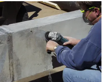
Figure 4.9: Application of Lokfix E ...47
Figure 4.10: Injection of Nitofill LV ...48
Figure 4.11: Specimen After Failure ...49
Figure 4.12: Test Configuration Used to Load the Specimens...50
Figure 4.13: Removal of Lokfix E Before Testing ...53
Figure 4.14: Hydraulic Jack Used During Loading...54
Figure 4.15: Concrete Compressive Test...55
Figure 5.1: Observed Crack Patterns...61
Figure 5.2(a): Initial Crack in S1 ...61
Figure 5.2(b): Failure Shear Crack in S1...62
Figure 5.3(a): Shear Crack in S2 after Post-tensioning...63
Figure 5.3(b): Failure of S2 after Epoxy Injection and Post-tensioning...64
Figure 5.4: Failure of S3 after Epoxy Injection and Post-tensioning...65
Figure 5.5: Failure of the Support...66
Figure 5.6: Effectiveness of Epoxy Injection ...67
Figure 5.7: Expected Load vs Deflection Plot for Specimens ...68
Figure 5.8: Load –deflection Relationship for S1 (Control Test)...69
Figure 5.9: Load- Deflection Relationship for S2 ...70
Figure 5.10: Load- Deflection Relationship for S3 ...71
Figure 5.11: Strain Measured in Shear Ligatures in S2...73
Figure 5.12: Failure of Shear Ligature after Epoxy Injection & Prestressing ...73
Figure 5.13: Strain Measured in Shear Ligatures in S3...74
Figure 5.13: Strain Measured in Tensile Steel of S2 ...76
Figure 5.14: Strain Measured in Tensile Steel of S3 ...77
Figure 5.15: Strain Gauge Rosette ...78
Figure 5.16: Concrete Strain After the Rehabilitation of Specimens S2 and S3 .79
Figure 5.17: Increase in Prestress Force as the Specimen is Loaded...80
Figure 5.18(a): Line Load Diagram ...87
Figure 5.18(b): Shear Force Diagram...87
Figure 6.1: Application of Epoxy Crack Injection and External PT to Tenthill Creek Bridge Headstocks...95
List of Tables
Table 3.1: Summary of Design Capacities...35
Table 4.1: Products Required for Epoxy Injection. ...46
Table 4.2: Tests carried out on the specimens...49
Table 5.1: Concrete Slumps ...57
Table 5.2: Concrete Compressive Strengths...58
Table 5.3: Steel Tensile Tests...59
Table 5.4: Strain Capacity of Reinforcing ...60
Table 5.5: Percentage Increase in Prestressing Force...81
Table 5.6: Corrected Flexural Capacities of Specimens ...86
Table 5.7: Corrected Shear Capacities of Specimens...86
Table 5.8: Theoretical Ultimate Applied Load for Specimens...87
Table 5.9: Experimental Specimen Capacities ...88
Nomenclature
The following list of notation has been utilised throughout the text. Where possible, notation for the Concrete Structures Standard, AS3600, has been used.
A = area of section in second moment of area calculations Ag = gross area of a concrete cross section
Asc = cross-sectional area of compression reinforcement
Ast = cross-sectional area of tension reinforcement
Asv = cross-sectional area of shear reinforcement
Asv-min = cross-sectional area of the minimum shear reinforcement
Asv-max = cross-sectional area of the maximum shear reinforcement
av = distance from load point to the face of the nearest support
b = width of a rectangular cross-section
bv = effective width of web for shear (equal to b for rect. cross- section)
Cc = compressive force in the concrete of a cross-section
Cs = compressive force in the compressive reinforcement
D = overall depth of section
d = depth to resultant force in tensile steel at Mu
dc = distance from extreme fibre to force Cc
dn = depth to the neutral axis in a section
do = distance from the extreme compressive concrete fibre to the centroid of
the outer most layer of tensile reinforcement dp = depth to the prestressing steel
dst = depth to centre of tensile reinforcement
e = eccentricity of the prestressing force from the neutral axis
f’c = characteristic compressive cylinder strength of concrete at 28 days
fsy = yield strength of reinforcing steel
Ig = second moment of area of the gross cross-section about centroidal axis
Ixx = second moment of area of a cross section about the principal X-axis
L = centre-to-centre distance between supports Leff = effective span of a beam or slab
Ln = length of the clear span, measured face-to-face of supports
Mdec = decompression moment
Mu = ultimate strength in bending
P = prestressing force
Pu = ultimate theoretical load capacity of a member
Pue = ultimate experimental load capacity of a member
Pv = vertical component of prestressing force
s = centre-to-centre spacing of shear reinforcement Tp = tensile force in prestressing steel
Ts = tensile force in tension reinforcement
Vdec = shear force at the decompression moment
Vu = ultimate shear strength
Vuc = ultimate shear strength of the concrete alone
Vus = contribution by shear reinforcement to the ultimate shear strength
yb = distance from centroidal axis to bottom fibre
β1β2β3 = multiplying factors for determining Vuc
γ
= ration of the depth of the assumed rectangular compressive stress block to dn at Muε
= strainε
cp = concrete elastic strain at tendon level due to prestressε
sc = compressive strain in the compression reinforcementε
st = tensile strain in the tension reinforcementε
u = extreme compressive fibre strain at ultimate strength in pure bendingθ
v = angle between the concrete compression strut and the longitudinalaxis of the member
σ
= stressσ
pu = stress in the prestressing steel at Muσ
sc = compressive stress in the compression reinforcementσ
st = tensile stress in the tension reinforcementC
HAPTER
1
I
NTRODUCTION
1.1.
Background
Over the past two decades the rapid deterioration of concrete bridge structures has become a serious problem in many countries. Approximately half of the modern concrete bridges in the world are approximately over 45 years old, therefore there is a growing concern regarding the structural quality of these bridges. There are a number of reasons for the deterioration of these structures including increased traffic flows and weight of vehicles, influence of
environmental pollution, low quality structural materials and limited maintenance programs (Radomski, 2002). The most common cause of
deterioration in bridges today is overloading. In engineering terms, overloading refers to applying loads to a member that are greater than that which they are designed for. In many cases the overloading is caused by the increased weight of transportation vehicles, such as trucks. This problem illustrates a clear need to develop a cost effective rehabilitation technique to restore the structures to their original working status.
This research is focused on developing a rehabilitation technique to repair
damaged bridge headstocks. It was mentioned earlier that a substantial amount of concrete bridge deterioration is due to overloading, as is the case with the
Tenthill Creek Bridge. The headstocks within the bridge are severely cracked, which dramatically decreases the load carrying capacity of the bridge. In order to
restore the structure to its original working condition, rehabilitation will be required. The objective of this research is to develop and analyse a method of repairing headstocks that could be utilised in the rehabilitation of concrete bridges in the future.
1.2.
Tenthill Creek Bridge
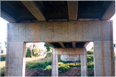
The Tenthill Creek Bridge is located approximately three kilometres west of Gatton in south-east Queensland. The bridge is situated on the Gatton-Helidon Road which was previously known as the Warrego Highway. Appendix A – Bridge Location Map shows the locality of the bridge. The bridge spans approximately 28 metres and is supported in three spans by column bent piers. These piers consist of a cap beam, or headstock, supported by two rectangular shaped piers, as seen in Figure 1.1. The piers are constructed on small spread footings which are supported by octagonal prestressed piles. Column bent piers are commonly used in highway bridges and are generally utilised where
[image:18.595.118.502.463.717.2]moderate clearance is required.
Figure 1.1: Tenthill Creek Bridge Headstock Configuration
Transportation of the Millmerran Power Station across the Tenthill Creek Bridge has caused substantial shear cracking in the headstocks. The severity of this cracking can be seen in Figure 1.2. These cracks extend vertically from the edge of the pier through the headstock and are approximately 1600mm long and 0.5mm wide. Since the headstocks are only 1700mm high, the cracks have almost extended the full height of the member. Consequently, almost the entire shear load is being carried by the reinforcement. If this load is greater than the yield strength of the reinforcement, the headstocks will almost certainly fail causing the bridge to collapse. Flexural cracking, also caused by overloading, can also be seen in the headstocks, however the cracks are far less critical. The flexural cracks will also require attention to ensure that they do not propagate any further into the member. It is obvious, that prompt attention is required to ensure the safety of motorists using the bridge.
Figure 1.2: Cracking in Headstocks
The south-east Queensland division of Main Roads has recently analysed the condition of the headstocks within the Tenthill Creek Bridge. Earlier, Main Roads rehabilitated the concrete girders within the bridge that were also showing signs of deterioration. This was completed by applying external post-tensioning
to the girders to increase their load carrying capacity. At the stage of this restoration, the condition of the headstocks was acceptable, therefore rehabilitation was not required. However, since then the headstocks have deteriorated to a state that now requires immediate attention. Main Rods have recently completed upgrading the headstocks. Therefore the designs for the rehabilitation techniques used for this research have been based on the work that was carried out on the bridge.
1.3.
Aims and Objectives
It has been mentioned above that many concrete bridges are deteriorating and will soon require some form of rehabilitation. The headstocks are a major structural member of these bridges, therefore they must be well maintained to ensure the stability of the bridges. The first aim of this research was to
investigate the effectiveness of epoxy injection and external post-tensioning as a form of shear strengthening concrete bridge headstocks. The rehabilitation technique that was used to undertake the experimental investigation for this research involved the use of both epoxy injection and external post-tensioning together.
The second aim of the research was accurately model the behaviour of the deteriorated Tenthill Creek Bridge headstocks. This requires scaling the original headstocks down to a model size that can be tested to predict the member’s behaviour in the future.
In order to achieve these aims, the following objectives had to be met: 1. Research background information on the use of epoxy injection and
external post-tensioning and determine the extent of their use within concrete bridge rehabilitation.
2. Investigate the state of the Tenthill Creek Bridge. 3. Design a model of the bridge headstocks.
4. Investigate and obtain a suitable epoxy resin to use in the experimental tests.
5. Design and develop a suitable external post-tensioning system. 6. Construct and test three specimens, one of which is used as a control
headstock.
7. Finally, critically analyse the shear capacity of the test specimens and advise on a suitable rehabilitation technique based on the findings.
1.4.
Effects of Research
In attempting to rehabilitate concrete bridges, it will inevitably cause some consequential effects. Through examining all of these effects that can be caused directly and indirectly, the consequences can be minimised. When examining the consequential effects of research such as this, three major aspects need to be addressed. These include aspects of sustainability, ethical responsibility and safety aspects. All three of these have been examined below.
1.4.1. Sustainability
Sustainability is one of the most important aspects of any engineering research conducted in today’s society. This includes environmental protection, protection of future generations and global protection. These all seem irrelevant when researching bridge rehabilitation, however with closer analysis many problems begin to emerge. Bridges are already set into the environment therefore
rehabilitation should have a minimal impact on the surroundings however, actions such as flora clearing, to carry out the work will impact on the environment. Also materials used to complete the work are produced from a finite source, meaning that materials to undertake the work are non renewable. Bridge deterioration is a global problem, therefore outcomes from any research will produce effects on a worldwide scale.
Conversely, not all of the sustainability issues will have a negative impact. For example the rehabilitation of these structures will preserve them for the use of future generations. Additionally, without some form for rehabilitation the bridges become disposable and therefore the impact on sustainability is much greater. The rehabilitation of concrete bridges will ultimately result in the utilisation of less finite resources and therefore improving sustainability aspects. Sustainability is a very controversial issue and many strong arguments can be made for and against the rehabilitation of concrete bridges. Transportation however is one of the most important aspects of the human race and without bridges, transportation would be severely confined.
1.4.2. Ethical Responsibility
It is important that all engineers abide by the appropriate code of ethics. Engineers are responsible for any actions that they undertake, even if they are directed to do so. Therefore all work needs to be closely analysed to ensure that it is not in breach of the code of ethics. The research surrounding the rehabilitation of bridge headstocks does not appear to breach any tenets of the code. With the implementation of the techniques into the field, the code may need to be more closely examined. It is important that this is done, as breaching any tenets of the code can generate serious consequences.
1.4.3. Safety
Finally, every engineering activity involves some form of physical risk to those who are directly and indirectly involved. When considering concrete bridge rehabilitation, these people would include construction workers undertaking the rehabilitation and also the general public who use the bridge. Short term
measures must be implemented to guarantee the safety of those undertaking the rehabilitation work. Some of these measures would include-
• Briefing all workers to ensure that they understand the safety issues relating to the project,
• Making certain that all workers are qualified to carry out specified tasks, this is vital when constructing prestressing systems, and
• Minimising all hazards within the workplace.
These are a few general measures that would need to be considered when undertaking a rehabilitation project. However, there are many more safety measures that would need to be considered surrounding a specific project.
When analysing the safety of those not directly involved with the project, such as the public, long term safety effects would need to be considered. Such effects would include-
• Any effects from pollution, for example long term chemical reaction of epoxy,
• Removal of any hazardous material, for example protruding steel, any chemicals used in construction,
• Ensuring the safety of the surrounding environment, this would include flora and fauna, etc.
Again, these are only a few general safety issues that would to be attended to, there would be many more site specific issues that would require analysis.
1.5.
Rehabilitation Techniques
The main focus of the research was to test the effectiveness of external post-tensioning on the shear strength of concrete headstocks under varying crack conditions. As stated above, the two rehabilitation techniques were used in this research included external post-tensioning and epoxy crack injection. Both of these techniques are introduced below.
1.5.1. Post-tensioning
External post-tensioning is a method of reinforcing or strengthening concrete members with high strength steel strands. To counteract shear cracking, the post-tensioning would work most effectively if was positioned vertically on the headstock (Figure 1.3(a)). Due accessibility problems associated with bridge headstocks, the post-tensioning is placed horizontally (Figure 1.3(b)). By applying the compressive force to the headstock, the shear cracks will close and
by doing so it is hoped that the aggregate interlock will be reformed. This process has been used for a number of years and the results have found to be effective. However how far can the extent of the shear cracking propagate before the aggregate interlock between the crack faces can not be reformed?
Figure 1.3(a): Vertical Post-tensioning
Figure 1.3(b): Horizontal Post-tensioning
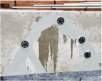
1.5.2. Epoxy Injection
Obviously once a shear crack becomes large enough, simply applying post-tensioning will not reform the aggregate bond between the crack faces as some movement will occur. Therefore another form of rehabilitation must be utilised to regenerate the bond. This can be done with the use of epoxy injection. The epoxy is a resin that is pumped into the crack that once cured will form a bond between the crack faces. The epoxy will restore the structural quality of the member and in most conditions it will make the structure ‘as good as new’. Another major advantage of the epoxy injection, is that by filling the cracks, penetration of moisture salts and other chemicals is prevented. Hence this will protect against the premature deterioration of the reinforcing and in some cases this is a crucial part of the rehabilitation process. This maybe a quality attribute of the epoxy, but the resins bonding properties is what was tested during this research. Below in Figure 1.4, an example of epoxy injection can be seen.
Figure 1.4:Epoxy Crack Injection
1.6.
Summary
The deterioration of concrete bridges is a problem that cannot be ignored, therefore a suitable method to counteract this problem is required. This research aimed to develop a suitable technique for the restoration of concrete bridge headstocks that can be utilised in the future. The project is also related to the case of the Tenthill Creek Bridge that is currently being restored. Many different forms of member rehabilitation techniques have been developed, however not many have utilised both epoxy and external post-tensioning together.
C
HAPTER
2
L
ITERATURE
R
EVIEW
2.1.
Introduction
Through researching this project it has been discovered that large amounts of work has been conducted in the area of bridge rehabilitation. This chapter will commence by presenting a brief overview of this work. The following section will identify work that has been undertaken in relation to external post-tensioning and epoxy crack injection.
2.2.
Concrete Headstock Rehabilitation
There is over 33,000 bridges in Australia alone, 50% of which are constructed of reinforced or prestressed concrete (Austroads 2002). It is estimated that in Australia alone, approximately $85 million is spent annually repairing or replacing aging concrete bridges (Austroads 2002). For this reason an extensive amount of research has been devoted to developing a viable and cost effective method of upgrading these aging structures.
It has been noted, by a number of publications, that the deterioration of concrete bridges is caused by a number of different reasons. Akasha and Farkas (1998) report that a majority of the concrete bridge deterioration is the result of poor maintenance, increased legal load limits, insufficient reinforcement, excessive
deflections, structural damage, corrosive attack or any combination of these. A majority of these structures are classified as deficient and in need of
strengthening or replacement. The design life of the structure is an important factor in the decision of whether to restore or replace a structure. Such a decision is generally influenced by site conditions, operational requirements, possible technical solutions and the cost-benefit relationship.
The strengthening of structural members can be achieved through a number of different processes. Some of these include replacing defective or poor material, attaching additional load bearing material (for example: reinforcement, high strength concrete, thin bonded straps, post-tensioning or a combination of these) or redistributing imposed loads (Dywidag-Systems International n.d.). All of these methods can be utilised as an effective form of rehabilitation, however the correct technique needs to be selected to suit the member’s requirements. It is noted by Pisani (1999), that external post-tensioning appears to be the most viable and cost effective form of bridge rehabilitation. In most cases a concrete bridge headstock is a relatively simple member to strengthen. The member is generally exposed on all sides apart from the top. This allows ample access to be able to apply many different rehabilitation techniques. Due to this exposure external post-tensioning can be easily fitted to most concrete bridge headstocks.
External post-tensioning is a rehabilitation technique that has been utilised for approximately sixty years (Stresscrete n.d.). The systems structural quality has been proven throughout this time. Conversely, epoxy injection is a relatively new system that has been introduced to the market in the past decade. In the past decade the system has proven to be a quality form of restoration. Research however into the use of epoxy injection and external post-tensioning together is limited. Consequently, the available literature can be broken down into two categories, rehabilitation with external post-tensioning and that with epoxy crack injection.
2.3.
External Post-tensioning
2.3.1. What is external post-tensioning?
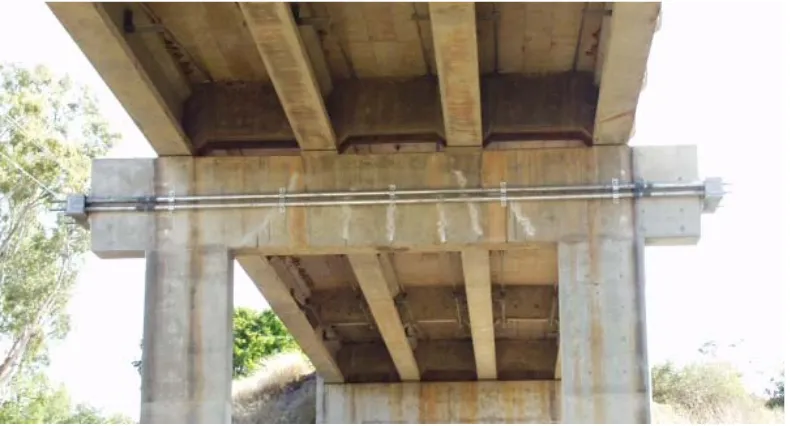
The Post-Tensioning Institute (2000) reports that external post-tensioning is an effective method of strengthening concrete. It uses high strength steel strands or bars referred to as tendons (Figure 2.1). This form of reinforcement is known as active reinforcement as it is prestressed, therefore it is effective before and after the member is cracked. Conventional reinforcement is known as passive
[image:28.595.114.509.512.725.2]reinforcement and only carries load after the member has cracked. Pisani (1999) identifies that external post-tensioning appears to be the most promising form of rehabilitation or strengthening of statically determinant structures, particularly bridges. Hwee (1997) believes that post-tension is an attractive method of strengthening concrete structures as it adds little weight to the original structure, its application poses little disturbance to the members surroundings and it allows the monitoring, re-stressing and replacement of tendons. Hwee (1997) has recently completed a three year study into the efficiency of the application of external prestressing in relation to beam strengthening. Through the course of his experimental work he concluded that by applying a prestress force to a beam with a small span-to-effective depth ratio, the likelihood of shear failure is dramatically decreased. Therefore it can be concluded that by applying post-tensioning to a bridge headstock, the members shear capacity will be increase.
Figure 2.1:External Post-tensioning Used to Strengthen Bridge Headstock
Pisani (1999) discovered that a member subjected to a single overloading case will not require rehabilitation as long as the cyclic loading produced by transport does not generate stress greater than the yield stress of the reinforcement. This may appear logical, however cyclic loading can cause strange outcomes within reinforcement and Pisani has only tested his theory to 10 000 cycles. Pisani (1999) also reports that if the above case is fulfilled, the member can be strengthened by means of prestressing and the load carrying capacity will be dramatically increased.
Dywidag-Systems International (n.d.) has reported that bridges of any material can be strengthened by adding external post-tensioning tendons. The influence of this rehabilitation on serviceability and ultimate limit states can be varied within wide limits by selecting different methods of introducing prestressing forces and using various tendon profiles. The correct tendon profile however needs to be selected to suit the rehabilitation required. This presents the effect of eccentricity. If the prestress force is applied above or below the centroid of the section by a certain eccentricity, a moment will be induced in the member. This moment is generally used to counteract moments induced by loading. When a member with external tendons deflects however, the tendon remains straight between the deviators or anchorages, hence altering the eccentricity (Figure 2.2). The change in eccentricity at a section becomes significant when the deflection of the section is relatively large compared to the members span (Ariyawardena & Ghali 2002). The effects of eccentricity variation should be accounted for when large
deflections are expected. This is accomplished by considering geometric nonlinearity in the analysis.
Figure 2.2(a): Post-tensioned Member Before Loading
Figure 2.2(b):Deflected Member
(Note the change in eccentricity at the centre section)
2.3.2. Problems Associated With External Post-tensioning One of the major problems associated with prestress in general is its
susceptibility to creep. The force in a prestressing tendon begins to diminish from the instance when the steel is first tensioned and continues throughout the life of the prestressed member (Warner et al 1998). Several factors contribute to the problem of creep. Some of these factors include:
1. Short term losses:
• elastic deformation of the concrete,
• elastic stretching of the tendon,
• friction between the post-tension tendon and the ducting, and
• slip of the anchorages. 2. Long term losses:
• stress relaxation of the tendons, and
• shrinkage of the concrete due to the prolonged applied load. During the design of the prestressing system, allowances should be made for these losses. This done by initially over-stressing the tendons to allow for the amount of creep that is expected (Warner et al 1998).
Another major problem connected to external post-tensioning is the effects of corrosion. Corrosion can be highly detrimental to prestressing as the tendons are under significant mechanical stress (Whiting, Corley & Tabatabai n.d.). Whiting, Corley and Tabatabai (n.d.) undertook various field investigations and
experimental testing into the corrosive problems associated with prestressing.
From their analysis they have recommended that periodic repair and
reapplication of protective systems may be necessary to guarantee the structural quality of the prestressing systems. Where such periodic repairs are difficult to implement, they suggest that complete replacement of distressed member may be a long-term cost effective alternative. Proper repair and rehabilitation of
deteriorating prestress systems is a primary concern of owners, therefore it is crucial that the effects of corrosion are not ignored.
In past decade, the quantity of post-tensioning systems sold has almost doubled and the industry is continuing to grow rapidly (Post-Tensioning Institute 2000). As the industry continues to grow, the cost efficiency will rapidly increase therefore making the system more viable for restoration applications. Many cases have been investigated after the application of the post-tensioning and it has been reported that the rehabilitation technique has been effective (Dywidag-Systems International n.d.). It is obvious therefore that this form of rehabilitation should be utilised in the future.
2.4.
Epoxy Crack Injection
The use of epoxy resins as a form of crack rehabilitation is relatively new to the construction world, however their use is becoming more and more popular (Figure 2.3). Epoxy injection is one of the most versatile problem solving products on today’s market. Epoxy Systems (2004) states that the structural restoration of concrete by epoxy injection is very often the only alternative to complete replacement. This technique can therefore lead to dramatic economic savings.
Figure 2.3:Epoxy Crack Injection
(Epoxy Systems 2004)
Epoxy Systems (2004) notes that epoxy injection serves two purposes:
1. It effectively seals the cracks to prevent damaging moisture entering, and 2. It monolithically welds the structure together.
The sealing properties of the injection, prevents premature failure of the reinforcing. This can be of equal or sometimes greater importance than the epoxy’s structural welding properties. Cracks left unprepared allow moisture, road salts and other contaminants to attack the reinforcing. Once the crack is penetrated, the rebar will deteriorate and hence loose its structural value. In extreme cases losing the entire structure can be the result. Therefore sealing these cracks is generally high on the list of priorities.
The other major purpose for using epoxy crack injection is the resins exceptional bonding properties. Epoxy Systems (2004) report that the epoxy’s bonding properties are good enough to restore a structure to it original condition. Minoru et al (2001) have undertaken laboratory tests on the bonding qualities of epoxy injection. From their analysis they have concluded that the resins will bond exceptional well to crack faces, however for precast segments the smooth face
should be removed before the resins are applied. Furthermore as a result of their analysis it could be concluded that depending on the quality of the resins and the application, a superior bond can be expected when crack injection is undertaken. One of the most important considerations that should be noted when utilising epoxy crack injection, is that the resins will repair the cracks, however they will not fix the cause of the cracking. This information is noted in almost all of the literature relating to this restoration technique. Demetrios and Tonias (1995) have discovered that a member subjected to an overloading condition which induces cracking can be repaired using the injection of epoxy resins. The
technique will only be effective however, if the overloading condition was a one off occurrence. If the crack is constantly reopened from the effect of general live loading, then crack injection will be ineffective as the crack will reform.
Demetrios and Tonias (1995) recommend that preloading the member until the injection material has reached a sufficient strength may help to overcome this problem. Generally it is essential however that the cause of the cracking be rectified during the rehabilitation process. This will eliminate the threat of the crack being reformed.
Epoxy resins are new in the field of concrete bridge rehabilitation therefore further research into this area may uncover more effective uses for the materials. This research is aimed at furthering knowledge of epoxy resins by using them in conjunction with external post-tensioning.
2.5.
Summary
External post-tensioning is a proven form of concrete rehabilitation. Under extreme crack conditions however, external post-tension becomes less effective due to the loss of aggregate bond between the crack faces. Epoxy injection is a relative modern technique for repairing cracks in concrete members. This form of rehabilitation is capable of reforming the aggregate bond that is lost between the crack faces. Consequently if the to techniques are combined, the load carrying capacity of the restored concrete member should be dramatically increased. This theory was tested through the course of this research.
C
HAPTER
3
D
ESIGN
O
F
T
HE
S
PECIMENS
3.1.
Introduction
This chapter presents an overview of the design work that has been undertaken during the course of the research. The section below presents the procedure used to develop a model the Tenthill Creek Bridge headstocks.
3.2.
Bridge Headstocks
It was noted earlier that the bridge is supported by column bent piers. The headstocks are a rectangular shape and have a trapezoidal cross section. The headstocks measure 1678mm high, 1068mm wide at the top and 686mm wide at the bottom. The overall length of the headstock is 9m. The types of
reinforcement used in the headstocks are equivalent to Y32 and Y16 rebar. Appendix C contains a copy of the bridge plans from when it was constructed. From these plans note the trapezoidal shape of the headstock. It is also shown that drainage provisions have been made within the headstock and bearing pads have been used to support the girders. Figure 3.1 below shows the constructed configuration of the headstocks.
Figure 3.1:Tenthill Creek Bridge Headstocks
3.3.
The Model
The design of the test specimens was produced by scaling the bridge headstocks down to a size that could be tested. Two different scales were initially chosen, ⅓
and ¼. The capacities of these two designs were then calculated and the ¼ size design was adopted. The capacity calculations are included in following sections. The adopted specimen size and section details are shown below in Figure 3.2.
Figure 3.2(a):Plan of Model Specimen
80
0
1540 380
38
0
42
0
2300
R6 – Shear Ligs N16 – Compression Rio
N16 – Tension Rio
420
220
Figure 3.2(b):Section Layout for Model Specimen
It can be seen in Figure 3.2(b), the section has been simplified from a trapezoidal shape to a rectangular shape for the model. This was completed to simplify the required design calculations and also the construction work. An average of the top and bottom distances of the trapezoid was taken to produce the rectangular section. Additionally the dimensions were then scaled by ¼ to develop the model. The reinforcement contained in the bridge was then scaled by an area ratio of 1:16 to determine the area of steel required in the specimen.
3.3.1. Flexural Capacity
The flexural capacity of the specimens is calculated to ensure the mode is shear failure rather than flexural. The calculations below were used to determine the flexural capacity of the member.
In a doubly reinforced section at ultimate moment (Mu), the resultant
compressive force C, consists of two component forces, Cc in the concrete and Cs
in the compressive steel (Figure 3.3). Therefore when determining Mu the two
forces are treated separately. After determining all of the forces and their point of action, Mu can be determined by assessing moments about the top most fibre.
ε
ub
21
(
28)
007 . 0 85 .
0 − ′−
= fc
γ
MPa fc′=32
(
32 28)
0.822 007. 0 85 .
0 − − =
=
2 600mm Ast =
2 400mm Asc =
MPa fsy =500
σ
stε
scσ
sc Ts Cc Cs dnN A zs
dst
ε
stSection Strains Stresses Internal
Forces Figure 3.3: Doubly Reinforced Section at Ultimate Moment
In an accurate proportioned section, the tensile steel will yield when Mu is
reached. Whether or not the compressive reinforcement will yield however will depend on the depth dsc relative to dn. Therefore when determining Mu for a
section, it is reasonable to assume that both the compression and tension steel yield to determine dn. Once dn is determined, the section can be reassessed to
determine if the assumption was correct. If the compression steel has yielded dn
will be correct, however if the yield point has not been reached the steel will still be in its elastic region and dn can be determined by using trial strain distributions.
This was required to determine Mu for the model specimen and the calculations
can be seen below.
• Mu for the Model Section
Section Properties Reinforcing Properties
Therefore Forces Equal: Tensile Steel Force:
N A
f
T = sy st =500×600=300×103
Compressive Steel Force:
N A
f
Cs = sy sc =500×400=200×103
Concrete Compressive Force:
n n
c
c f bd d
C =0.85 ′γ =0.85×32×0.822×220 N dn 85 . 4918 =
∑
3 310 300 10 200 85 .
4918 dn + × = ×
→ =0
H
mm dn =20.33
Therefore the tensile steel clearly yields, however the compressive steel:
n sc n u sc d d d − =ε ε
( )
εsy0025 . 0 0035 . 0 33 . 20 44 33 . 20 003 .
0 ⎟=− <
⎠ ⎞ ⎜ ⎝ ⎛ − =
The assumption that the compressive steel had yielded is invalid, hence dn is
solved by a trial and error approach, iterating on assumed values of dn until the
equilibrium condition of Cc + Cs – T = 0.
Note an example of the working for the trial and error process can be seen in Appendix D.
Try dn = 52.833mm
Compressive Steel Strain:
0005 . 0 833 . 52 44 833 . 52 003 .
0 ⎟=
⎠ ⎞ ⎜ ⎝ ⎛ − = sc ε
Compressive Steel Force:
N Cs =0.0005×200000×400=40124.92
Concrete Compressive Force:
N d
Cc =4918.85 n =4918.85×52.833=259877.5
Tensile Steel Force (As Before):
N T =300×103
Check Equilibrium: 0 42 . 2 10 300 92 . 40124 5 .
259877 + − × 3 = ≈
=
∑
HFrom these values (Cc, Cs and T), Mu can be calculated by assessing the moments
about the top fibres.
Leaver Arms:
mm
dc 21.71
2 833 . 52 822 .
0 × =
=
dsc = 44mm (ie. Depth to compressive steel)
dst = 420 – 30 – 6 – 8 = 376mm (ie. Depth to the tensile steel)
Calculate Mu:
sc s c c st
u Td C d C d
M = − −
(
300×103×376)
−(
259877.5×21.7) (
− 40124.92×44)
=
u
M
kNm Mu =105.40
From Mu the ultimate force required to produce the moment can be determined
from:
ab L M Pu = u eff
P
Leff
b a
Where:
Leff = Min(L; Ln + D)
Therefore:
Leff = L = 2300 - (190 x 2) = 1920mm
The specimens were loaded at ⅔ of the top distance (ie. 775mm) along the specimen. Therefore:
a = 1920 – 585 = 1335mm b = 775 – 190 = 585mm
Calculate Pu:
kN
Pu 259
585 1335
1920 10
40 .
105 6
= ×
× × =
This force can now be assessed against the ultimate shear capacity of the member to determine the mode of failure during loading. The research is based on shear analysis, therefore the specimens should be designed to ensure that shear failure does occur. This force also needs to be checked against the ultimate capacity of the loading equipment to determine if the specimens can be tested.
3.3.2. Shear Capacity
Determine the ultimate shear strength (Vu) of the section.
R6 – Shear Ligs
s = 280mm fsy = 250MPa Cover = 30mm
420
220 do
• Ultimate Shear Strength (Vu)
Vu = Vuc + Vus
Ultimate Shear Strength of the Concrete: 3 1 3 2 1 ⎥ ⎦ ⎤ ⎢ ⎣ ⎡ ′ = o v c st o v uc d b f A d b V β β β
1 . 1 1000 6 . 1 1 . 1
1 ⎟≥
⎠ ⎞ ⎜
⎝
⎛ −
= do
β
346 . 1 1000 376 6 . 1 1 . 11 ⎟=
⎠ ⎞ ⎜ ⎝ ⎛ − = β
• The factor β2 is used to account for the effect of an axial load such as
prestressing, however in this case no axial load is present, therefore β2 =
1.0.
0 . 2 2
3 ⎟⎟≤
⎠ ⎞ ⎜⎜ ⎝ ⎛ = v o a d β 904 . 1 395 376 2
3 ⎟=
⎠ ⎞ ⎜ ⎝ ⎛ × = β
• The factor β3 is used to account for large concentrated loads near the
support of the member. Hence due the configuration of the specimen, β3 ≠
1.0. β3 is calculated by the formula:
Where avis the distance from the inside of the support to the load point.
Therefore:
av = 395mm
Therefore: 3 1 376 220 32 600 376 220 904 . 1 0 . 1 346 . 1 ⎟ ⎠ ⎞ ⎜ ⎝ ⎛ × × × × × × × = uc V kN Vuc =130.29
Ultimate Shear Strength of Reinforcement:
v o sy sv us f d
s A
V = cotθ
Determine the angle between the concrete compression strut and the longitudinal axis of the member (θv). The Asv, the area of the stirrup, is known, θv can be
calculated using: ⎥ ⎦ ⎤ ⎢ ⎣ ⎡ − − + = − − − min max min 15 30 sv sv sv sv o o v A A A A θ
Calculated the maximum and minium stirrup areas:
2 min 86 250 280 220 35 . 0 35 . 0 mm f s b A sy v
sv− = = × × =
Asv-min is large due to the conservative yield stress of the R6, hence the quantity
of steel used in the beam is less than Asv-min. As a result, θv can be calculated
within a range of values from 30o to 45o. This is not conventional, however as Asv is small, when using the equation above, θv is approximated at less than 30o.
Therefore by calculating Vu over a range of values an approximate idea of the
ultimate shear strength will be given. For θv = 30o:
( )
kN Vus 250 376 cot 30 36.05280
62 × × × =
=
For θv = 45o:
( )
kN Vus 250 376 cot 45 20.81280
62 × × × =
=
Calculate Vu:
Vu = Vuc + Vus
For θv = 30o:
Vu = 130.29 + 36.05 = 166.34kN
For θv = 45o:
Vu = 130.29 + 20.81 = 151.10kN
Note that the ultimate shear strength (Vu) of the specimen is dramatically smaller
than the load required to induce the ultimate moment (Mu). The design has been
developed in this way to ensure that when the testing is undertaken, the specimen will fail in shear. Additionally, the area of the shear reinforcement has been directly scaled from the bridges reinforcement. Therefore the area of the shear reinforcement in the bridge is also low, resulting in the development of the shear cracks.
3.4.
Prestress Design
The load capacity of the specimens is expected to increase after the application of the prestressing. Consequently, the ultimate capacities after the application of the prestress needs to be determined to ensure that the available testing
equipment is capable of failing the specimens. The sections below present the analysis undertaken to determine these capacities.
The force induced in the external post-tensioning, for this research was
developed by scaling down the force that was applied to the rehabilitation of the Tenthill Creek Bridge. A total of four tendons were attached to the bridge and each was stressed to 1000kN, inducing a total force of 4000kN. This force was scale by the ratio of 1:16 to produce a force of 250kN be applied to the test specimens.
3.4.1. Flexural Capacity
Again the flexural capacity of the specimens after prestressing needs to be assessed to ensure that shear failure will occur.
When analysing the effects of prestressing on a beam, it generally assumed that any change in concrete strain will also occur in the steel. In the case of external unbonded tendons, the steel stress remains constant over the full length of the beam. Consequently, various conservative approximations have been developed to allow the stress in the unbonded tendons at ultimate moment to be estimated. In AS3600 Clause 8.1.6, two expressions are specified for approximation this tendon stress. For the purpose of this research, it has been assumed in the analysis that the stress in the external tendons does not increase as the member deflects. This will provide conservative results that are accurate enough for the purpose of this analysis.
The analysis used to determine Mu for the prestressed section is similar to that
used above in section 3.3.1. The analysis can be seen below.
Figure 3.4: Doubly Reinforced Section with External PT at Mu
The section properties and reinforcing properties are the same as that in section 3.3.1 above.
Initially assume that all reinforcement yields before Mu is reached.
zs Internal Forces Stresses Strains Section Cs Cc Tp Ts
σ
scε
scγ
dnε
uσ
stσ
pu b dst dn dpε
cpε
st N ADetermine the forces:
N A
f
Ts = sy st =500×600 =300×103
N A
f
Cs = sy sc =500×400=200×103
n n
c
c f bd d
C =0.85 ′γ =0.85×32×0.822×220 N dn 85 . 4918 = N Tp =250×103
∑
4918.85 +200×103 =300×103 +250×103n d → =0 H mm dn =71.15
Therefore the tensile steel clearly yields, however the compressive steel:
28
( )
sy scε =0.003⎜⎛71.15−44⎟⎞=0.0011 0.0025ε
15 .
71 ⎠ <
The assumption that the compressive steel had yielded is invalid, hence dn is
solved by a trial and error approach, iterating on assumed values of dn until the
equilibrium condition of Cc + Cs – T = 0.
Note an example of the working for the trial and error process can be seen in Appendix D.
From trial and error, dn = 87.545mm The forces equal:
Cs = 119376.3N Cc = 430620.5N Ts = 300 x103N Tp = 250 x 103N
Calculate Mu using these forces, by taking moments about the top most fibres.
Leaver Arms:
mm dc = 0.822 35.98
2 545 . 87 = ×
dsc = 44mm dst = 376mm
dp = 220mm (ie. depth to the prestress force)
Calculate Mu
sc s c c st s p p
u T d T d C d C d
M = + − −
(
250×103×220) (
+ 300×103×376)
−(
430620.5×35.98) (
− 119376.3×44)
=
u
M
kNm Mu =147.05
Calculate the ultimate load to induce Mu from the equation set out above in
section 3.3.1.
kN
Pu 361.52
585 1335 1920 10 05 . 147 6 = × × × =
Note that this load is substantially larger than the load that was calculated above in section 3.3.1. This increase in strength is due to the effects of the external post-tensioning. Theoretically, by applying the post-tensioning system, in increase in strength of around 35% can be expected. Additionally, note that Pu is
less than the capacity of the testing equipment that is to be utilised.
3.4.2. Shear Capacity
Once external post-tensioning is applied to a member, flexure-shear cracking becomes evident. The crack is initiated by flexure, however as the load is increased, the crack begins to turn towards the load point and shear cracking becomes evident. An estimate of the load required to produce the shear crack can be obtained by determining the load at which the flexural crack occurs and adding to it an estimate of the load required to turn the crack. There is no reliable way of determining the load that is required to turn the crack, however a
simplified approach has been adopted in AS3600. The equation for Vuc given in
the Standards is:
(
)
v dec o v c pt st o vuc V P
d b f A A d b
V ⎥ + +
⎦ ⎤ ⎢ ⎣ ⎡ + ′ = 3 1 3 2 1β β β
Vdec is the shear force at which a state of decompression occurs and can be
calculated by: ⎟ ⎠ ⎞ ⎜ ⎝ ⎛ = * * V M M V dec dec
Where the decompression moment Mdec is calculated by:
b g b g g dec y I y I Pe A P M ⎥ ⎥ ⎦ ⎤ ⎢ ⎢ ⎣ ⎡ + =
In the case off the research specimens, the eccentricity of the prestressing force is equal to zero, therefore the equation can be simplified to:
b g g dec y I A P
M = .
Where: 4 9 3 3 10 358 . 1 12 420 220 12 mm bd
Ig = = × = ×
Therefore:
kNm
Mdec 17.50
210 10 358 . 1 420 220 10
250 3 9
Calculate Vdec using the moment and shear capacities determined in sections
3.3.1 and 3.3.2.
kN
Vdec 17.35
10 48 . 104 10 40 . 105 10 50 . 17 3 6 6 = ⎟⎟ ⎠ ⎞ ⎜⎜ ⎝ ⎛ × × × =
Pv is used to account for the vertical component of the prestressing, however in
this case Pv = 0 as the profile of the tendons is horizontal.
Calculate the shear strength contributed by the concrete:
(
)
3 31 10 35 . 17 376 220 32 531 600 376 220 904 . 1 0 . 1 346 .
1 ⎟ + ×
⎠ ⎞ ⎜ ⎝ ⎛ × × + × × × × × = uc V kN Vuc =178.29
From above, the shear strength contributed by the reinforcement (Vus) is:
For θv = 30o:
kN Vus =36.05
For θv = 45o:
kN Vus =20.81
Calculate Vu:
Vu = Vuc + Vus
For θv = 30o:
Vu = 178.29 + 36.05 = 214.34kN
For θv = 45o:
Vu = 178.29 + 20.81 = 199.10kN
Again observe that the ultimate shear capacity of the prestress section is less than the load to induce the ultimate moment. This will ensure that even after
prestressing, the specimen should still fail in shear. Based on the theoretical analysis, an increase in the order of 35% can be expected in the shear capacity of the section after prestressing is applied.
3.5.
Second Moment of Area
The second moment of area (I) of a section represents the sections stiffness. Therefore it is essential when modelling a section, the I value of both the actual and model sections are similar. The calculations below show the analysis undertaken to determine the (I) values for the Tenthill Creek Bridge headstocks and also the model headstocks.
X Y A 1678 y x 1068 900 686 y y x x
Figure 3.5:Second Moment of Area Analysis
Figure 3.5 above portrays the section of the Tenthill Creek Bridge Headstocks. The centroid of the section is marked by the principal axes X-Y in Figure 3.5. The centroid was found by dividing the section into simple shapes and deriving the point from these shapes using the equation:
(
)
(
∑
)
∑
= i i i A x A yNote the section is symmetrical about the Y-axis therefore calculations were not required to find the location of the centroid in the X direction.
The working for this process can be seen in Appendix D.
The second moment of area (I) can now be determined about the principal axes using the equation:
(
)
∑
+ = 2 i i xi xx I AyI
Note the I-value about the X-axis is only required as this will provide enough information to compare the actual and model sections.
The working for determining Ixx can be seen in Appendix D.
Ixx for the bridge section:
Ixx = 3.393 x 1011mm4
Calculate Ixx for the model section:
4 9 3
3
10 358 . 1 12
420 220
12 mm
bd
Ixx = = × = ×
A scale factor of 1:250 needs to be applied to the model I-value to compare it with the actual I-value.
(
1.358 109)
250 3.395 1011 4mm Ixx−adj = × × = ×
From this adjusted I-value, it is evident that by modelling the member as a rectangular section, the stiffness will only alter by a minor amount. Therefore the results obtain from the model testing are comparable to the actual bridge
headstocks.
R6 – Shear Ligs S = 280mm
N16 – Compression Rio
N16 – Tension Rio
420
220
3.6.
Design Summary
80
0
1540 380
38
0
42
0
2300
Figure 3.6: Specimen Design
Figure 3.6 above shows the design that was used to construct the three specimen to carry out the research. The theoretical strengths of the specimens before and after prestressing according to AS3600 are shown in Table 3.1 below.
Table 3.1:Summary of Design Capacities
Strength Property Strength Before Prestressing (kN)
Strength After Prestressing (kN)
Theoretical Strength Gain
(%)
Flexural 259 362 40
Shear 151 - 166 199 - 214 30.5
Note from these values that before and after prestressing, the shear strength is much lower than the flexural strength. The section has been designed in this manner a