University of Southern Queensland
Faculty of Engineering & Surveying
The Design of a Three Point Linkage Implement
Height Control System
A dissertation submitted by
Mr Daniel John Clarke
in fulfilment of the requirements of
Courses ENG4111 and ENG4112 Research Project
towards the degree of
Bachelor of Engineering (Mechanical)
ABSTRACT
The purpose of this project was to design a height control system that could be applied to a Three Point Linkage mounted implement. Several methods of achieving this goal were investigated. The two methods that were investigated in detail were an electrical over hydraulic system and a mechanical over hydraulic system.
The unique operation of the three point linkage implements when lift assist is used presents problems when accurate frame height is required, such as when seeding operations are being performed. The system has been designed so that it is constantly sensing the height of the frame at both ends of the implement. The output from this sensing is used to control a hydraulic valve mechanically or electrically. If a height discrepancy between the front and rear of the implement is detected, this valve will be activated to allow a flow of hydraulic oil to the lift assist system, levelling the implement.
The investigation of the electrical control system involved constructing a prototype circuit that was based on a PICAXE microcontroller to provide computing power. This chip was programmed to read the output from two variable resistors and detect any height discrepancies. When a discrepancy was detected, the microcontroller activated a
servomechanism that used mechanical motion to correct the position of one of the resistor to match the mechanical position of the two resistors, thus proving the concept of
mechanical height control.
University of Southern Queensland
Faculty of Engineering and Surveying
ENG4111 Research Project Part 1 &
ENG4112 Research Project Part 2
Limitations of Use
The Council of the University of Southern Queensland, its Faculty of
Engineering and Surveying, and the staff of the University of Southern
Queensland, do not accept any responsibility for the truth, accuracy or
completeness of material contained within or associated with this dissertation.
Persons using all or any part of this material do so at their own risk, and not at
the risk of the Council of the University of Southern Queensland, its Faculty of
Engineering and Surveying or the staff of the University of Southern
Queensland.
This dissertation reports an educational exercise and has no purpose or validity
beyond this exercise. The sole purpose of the course pair entitled "Research
Project" is to contribute to the overall education within the student’s chosen
degree program. This document, the associated hardware, software, drawings,
and other material set out in the associated appendices should not be used for any
other purpose: if they are so used, it is entirely at the risk of the user.
Professor R Smith
Dean
CERTIFICATION
I certify that the ideas, designs and experimental work, results, analyses and conclusions set out in this dissertation are entirely my own effort, except where otherwise indicated and acknowledged.
I further certify that the work is original and has not been previously submitted for assessment in any other course or institution, except where specifically stated.
Student Number:
______________________________ Signature
ACKNOWLEDGMENTS
TABLE OF CONTENTS
Abstract... i
Certification... iii
Acknowledgments ... iv
Table of Contents ... v
List of Figures... viii
List of Tables ... x
Glossary ... xi
Chapter 1 – Introduction ... 1
1.1 Introduction ... 1
1.1.1 Background Information ... 1
1.1.2 Recent Design Improvements ... 3
1.1.3 Objectives ... 7
1.2 Assessment of Consequential Effects ... 8
1.3 Project Methodology ... 8
1.4 Risk Assessment... 9
1.5 Resource planning ... 10
I LITERATURE REVIEW Chapter 2 – Senstek DCM-2 depth control system... 11
2.1 Review of Depth Control Systems ... 11
2.2 Ultrasonic Sensing System... 12
2.3 Testing... 13
2.4 Conclusions drawn from testing... 14
Chapter 3 – Inventronics Depth Master depth control system... 15
3.1 Height Sensing Wheel Height Control System ... 15
3.2 Testing... 16
3.3 Conclusions drawn from testing... 17
Chapter 4 – Sensing technology... 18
4.1 Sensor Application ... 18
4.3. Ultrasonic transducers ... 19
4.4 Direct mechanical control ... 21
II CONTROL MECHANISM DESIGN Chapter 5 – Electronic control... 22
5.1 Design guidelines for an electronic system... 22
5.2 Description of the PICAXE microcontroller... 23
5.3 Operation of the PICAXE system ... 23
5.4 Construction of the model system... 25
5.5 Programming the model ... 28
5.6 Description of Program_1 ... 29
5.7 Testing of Program_1 and Results ... 32
5.8 Description of Program_2 ... 34
5.9 Testing of Program_2 and Results ... 35
5.10 Relevance of the model ... 36
Chapter 6 - Design of a height sensing wheel ... 38
6.1 Design Outline... 38
6.2 Design constraints ... 39
6.3 Height control wheels... 40
6.3.1 Wheel positioning... 40
6.4 Design of height sensing wheel... 42
6.4.1 Materials selection... 42
6.4.2 Manufacturing method ... 44
6.5 Parallelogram Mechanism... 46
6.6 Spring Design ... 49
6.7 Design of castor frame ... 54
6.8 Hub design and wheel selection ... 56
6.9 Spool valve control... 60
6.10 Spool valve selection... 63
Chapter 7 - Control system design ... 65
7.1 Design outline ... 65
7.3 Design review... 69
7.4 Construction ... 71
Chapter 8 – Design verification ... 74
8.1 Analysis of the main control linkage... 74
8.1.1 Vibration analysis ... 74
8.1.2 Strength analysis... 77
8.2 Stress analysis of castor frame ... 78
Chapter 9 – Summary and conclusions ... 84
9.1 Summary ... 84
9.2 Further Work ... 85
9.3 Conclusions ... 87
List of references ... 88
III APPENDICIES Appendix A: Project specification... 91
Picaxe Programs... 93
Program_1 ... 93
Program_2 ... 96
Schematics of the eight chip types ... 98
LIST OF FIGURES
Figure 1.1: Image of a three point linkage planter fitted to a tractor ... 2
Figure 1.2: Photograph of a three point linkage system ... 4
Figure 1.3 Gyral zero-till planting system ... 5
Figure 1.4 Homan three point linkage zero-till planting system ... 6
Figure 2.1. Parts making up the Senstek DCM-2 depth control system ... 12
Figure 2.2. Parts making up the Inventronics Depth Master depth control system ... 16
Figure 5.1 - Images of the 18 pin (left) and 28 pin devices ... 23
Figure 5.2: Image of the PICAXE chip installed onto the breadboard ... 25
Figure 5.3 PICAXE-18/18A/18X minimum operating circuit ... 26
Figure 5.4 Image of the system used to test the operation of the PICAXE chip ... 28
Figure 5.5: Graphical indication of the system response from program_1... 33
Figure 6.1: Image depicting the disadvantage of a trailing front wheel ... 40
Figure 6.2: Image depicting desired wheel layout ... 41
Figure 6.3: Image depicting the final design concept of the wheel frames ... 42
Figure 6.4: Diagram of proposed pivot design ... 45
Figure 6.5: Image showing the final parallelogram design... 46
Figure 6.6: Secondary image of the final parallelogram design ... 48
Figure 6.7: Image of the parallelogram mechanism at two height extremes ... 51
Figure 6.8: Image showing the redesigned spring stops ... 54
Figure 6.9: Two images of the castor frame ... 55
Figure 6.10: Image of the tyre that will be used ... 57
Figure 6.11: Image of the hub model... 57
Figure 6.12: Image of the final mechanism model ... 59
Figure 6.13: Close up image of the castor frame pivot... 59
Figure 6.14: Image of a hydraulic ram... 60
Figure 6.15: Diagram of the operation of an open spool valve ... 61
Figure 6.16: Image of a quick hitch coupling ... 62
Figure 6.17: Image of a spool valve similar to the one being specified here ... 63
Figure 7.1: Conceptual image of the valve control mechanism design ... 65
Figure 7.4: Image depicting all of the relevant linkage pivots ... 68
Figure 7.5: Image showing the final mechanism assembly ... 71
Figure 7.6: Image showing the critical collar dimensions for table 7.2... 73
Figure 8.1: Images of the real and simplified main linkage cross section... 74
Figure 8.2: Beam loading scenario ... 77
Figure 8.3: A diagram depicting the restraints and loads used in the stress analysis ... 80
Figure 8.4: An image of the stress distribution after finite element analysis ... 80
Figure 8.5: Another image showing the stress distribution in the model ... 81
LIST OF TABLES
GLOSSARY
Implement: Any device drawn behind a tractor to perform an agricultural operation. In this
context, the word implement refers to a device that either mechanically prepares the soil or places seeds and other material such as fertiliser into the soil
Tractor: A vehicle used to provide tractive effort and height control to the implement
Tine: a ground engaging device that creates a slot in the ground for the seed to enter
Air Seeder: A device that uses a flow of air to deliver the seed and fertiliser from the
storage hopper to the implement
Distributor head: A device that separates the seed and fertiliser from the airflow from the
Air Seeder and distributes the solid material to the individual tines
Three Point Linkage: A system used to connect an implement to a tractor using three
points of attachment
Lift Assist: A system of wheels that attaches to the rear of a Three Point Linkage
implement that supports the weight of the rear of the implement
Hydraulic Ram: A device consisting of a cylinder and piston that converts a flow of
hydraulic fluid oil into linear motion
Servo: An abbreviation of servomechanism, which is an geared electric motor used for
CHAPTER 1 – INTRODUCTION
1.1 Introduction
1.1.1 Background Information
Modern farming has become a global enterprise where farmers compete on an international playing field for the ultimate goal of making the largest profit possible. Australian farmers must overcome many obstacles including often poor commodity prices, competition with increasingly subsidised European and American farmers (Reynolds, 1999), an
unpredictable climate and the increasing prevalence of drought (The Australian, 2006) and the rising cost of raw materials such as fuel and fertiliser. The local response to these problems in the past has been the rapid increase in the efficiency of the farming process and timely innovation (Howard, 1992).
The adoption of the zero till planting method is a prime example of this increase in
efficiency, as economically and environmentally undesirable soil erosion has been reduced under this system (Plaster, c. 2002). More fuel efficient tractors, cheaper herbicides and the adoption of GPS (Global positioning system) to guide tractors have also slightly decreased the cost of crop production. As efficiency is the Australian farmer’s main weapons in the battle for profit, it is important to continue to come up with better ways to farm so the advantages that the Australian farmers now have are not lost.
Tonks, 1981). Another factor to consider is that humans do not like to spent weeks on end working long days, so larger equipment is appreciated by the operator.
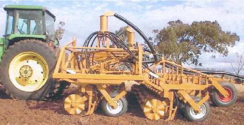
[image:14.595.96.508.327.539.2]Larger Three Point Linkage machines combine simplicity with size and are a natural progression of the move towards more efficient farming methods. These machines can require less material in their construction due to the absence of a large hitch and a reduction in the number of weight bearing wheels. Figure 1.1 shows a Three Point Linkage machine that displays these attributes to some extent, i.e. there is no long hitch and only two weight bearing wheels. These types of systems have several design flaws that are made more acute by an increase in size. These issues and the rectification of these issues are the subject of this project.
Figure 1.1: Image of a three point linkage planter fitted to a tractor Source:
1.1.2 Recent Design Improvements
Large equipment requires a large amount of steel, and engineering and manufacturing costs are higher. It makes sense that planting equipment be simplified so certain parts are made redundant. Three point linkage planters are one example of this trend. Figure 1.1 shows a large, modern trailing seeding implement. Several features are evident in this image (the tractor is obviously not shown). The large hitch and multiple support wheels are several items visible in the image. A trailing air seeder is visible at the rear of the machine. The distributor heads are visible above the frame at the left and right of the planter. A casual observation of the frame of the planter makes it clear that a large quantity of steel has been used in its construction.
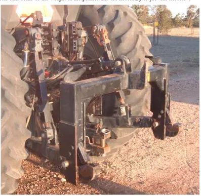
Figure 1.2 shows another option that is available to farmers. This system takes all of the parts of the system previously described and incorporates it into one compact unit. This system uses the three point linkage device of the tractor to provide draft and height control. Three Point Linkage is a system that connects the machine to the tractor with three arms. This transfers the weight to the tractor and allows the tractor to raise and lower the
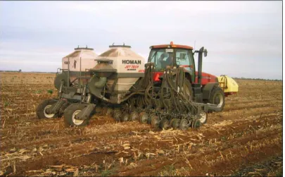
Figure 1.2 shows an image of a typical three- point linkage system at the rear of a Case 8950 tractor. This tractor features a quick hitch system which is a device that allows rapid connection of the implement. The three control arms and three points of connection that give the system its name can clearly been seen in this image. The introduction of larger tractors that have three point linkage systems has been one reason behind an increased need for Three Point Linkage planters. One notable feature of the planter in figure 1.4 is the two large wheels situated behind the planter. This is a recent innovation called lift assist. This is simply the placement of wheels behind the planter frame. These wheels are raised and lowered by hydraulic rams operated with the tractor’s auxiliary hydraulic system. These wheels take some of the weight of the planter and are necessary to prevent excessive
weight transfer to the rear wheels of the tractor. This system also allows the air seeders to be mounted directly to the rear of the planter, as has happened in figure 1.4. Almost all large three point linkage planters utilise this system.
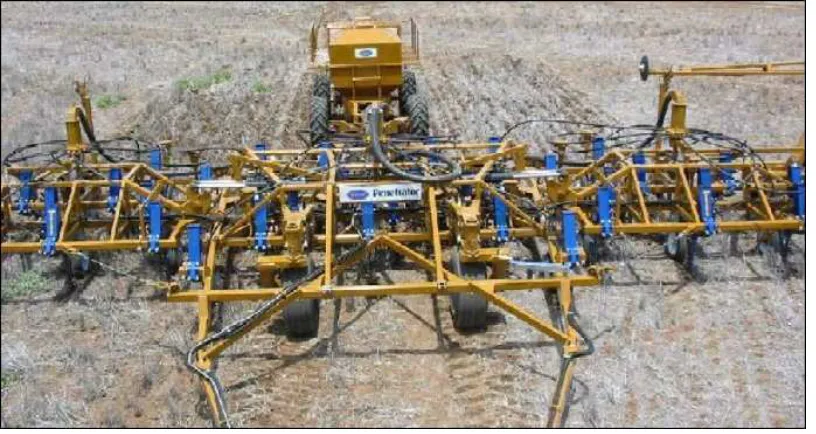
Figure 1.3 Gyral zero-till planting system
Source: http://www.gyral.com.au/images/Penetrator.JPG (2006)
It can be seen from comparison between figures 1.3 and 1.4 that a conventional planting system can be greatly simplified with the application of sound engineering principles. It is the improvement of the three point linkage system that is the subject of this project.
Figure 1.4 Homan three point linkage zero-till planting system
Source: http://www.homan.com.au/Airseeders/Airseeders.asp (2006)
These actions become difficult for the driver when the tractor must be steered at the same time as the implement is lifted, as three actions are needed. This means that the driver must lift the implement well before the end of the run is reached and then start to turn. These actions must be repeated after the machine has been turned, although obviously the
implement is lowered instead of raised. The two independent height inputs mean that it can be difficult to level the machine from front to back, and the machine must be adjusted prior to use by placing travel limiters on the shafts of the lift assist hydraulic rams. It can be difficult and time consuming to get this adjustment correct.
1.1.3 Objectives
The aims of this project are to develop an automatic height control system that will sense when the implement is not level. When this occurs, a hydraulic control valve will be actuated, and oil will flow into the appropriate side of the lift assist hydraulic system which will in turn level the implement. The overall effect of this system will be to keep the rear of the implement at the same height as the three point linkage height setting.
Two types of height control will be investigated. The first is electrical over hydraulic, in which sensors are used to measure the height of the front and rear of the implement and a computer processes the information from the sensors. If a height discrepancy is detected, the computer sends a signal to a solenoid operated hydraulic valve to provide oil flow to correct the height of the lift assist system.
The second type of system that will be investigated is a fully mechanical sensing system that uses linkages to actuate a hydraulic valve to restore the rear of the implement to the correct height. If it is decided that this system is the most appropriate device, it will be designed using a solid modelling package.
1.2 Assessment of Consequential Effects
The device that is being designed during the completion of this project will be
mechanically simple, however if any part of the implement is used to physically support any part of a planting implant, this presents a safety risk in the case of failure. For example, if the implement was in the raised position and a mechanic was underneath the frame servicing it, there needs to be no chance of sudden failure. It is, therefore my duty to design any load bearing device to national standards using best practice engineering knowledge. If the control system utilises electronic components in any form, it is important to ensure that they do not pose an electrical hazard. It is very unlikely that this would occur, however, as the system will be designed to run on a very safe 12 volts. This will be necessary as almost all tractors have 12 volt electrical systems.
As this device is to be mounted to an agricultural machine that physically affects the soil, this technology could cause an environmental impact. It should be noted that the author is not designing the implement or the ground engaging devices, only a height control system. Therefore as the function of the implement is unchanged, any adverse environmental impacts would have been directly a result of either irresponsible farming practices or a poorly designed planting machine. Modern farming practices are as environmentally friendly as possible and any responsible farmer is always conscious of potential damage to the environment, so this is unlikely to be an issue.
1.3 Project Methodology
linkage machines that would benefit from height control. This process will involve research into specifications such as current machine sizes and the lifting weights of tractors.
The next logical step is to attempt to find if anyone has designed a similar system and try to find the performance of their device/s to guide this design in the right direction. After several systems have been investigated, it will be possible to use this information to come up with several unique solutions to the problem of height control. After this has occurred, research will be conducted into the operation of a three point linkage planting machine and features will be identified that will need to be exhibited for successful operation of the seeding machine.
The next step will be to design the system in a way that would be most suitable for the expected operating conditions. An electro/mechanical system will be designed to start with. A prototype circuit will be constructed and simulated operating conditions will be used to test whether it will work effectively in the field. If this is not the case, a wholly mechanical control system will be designed. All mechanical parts will be designed in a solid modelling program. The features and analysis of the final design will then be reported on as a
conclusion to the project.
1.4 Risk Assessment
There are only plans for one prototype system to be made, and this is the electronic control system for the depth control unit. As the construction of this device is the only planned physical work planned, the risk assessment will be based on this only. This device is a simple circuit, consisting of several simple components. All of these components will be rated to twelve volts to safely handle the planned input voltage. There are two feasible hazards involved in the construction and testing of this circuit. The first is the risk of electric shock. As the voltage is so low, the risk of this occurring is extremely slight. The nature of the testing means that the level of exposure to this hazard will be almost
a slight tingling sensation. The benign nature of this risk means that no controls will be implemented to prevent its occurrence.
The other possible risk is that a component such as a capacitor could be installed incorrectly. The risk of this situation arising is significant, as the circuit calls for a very specific layout of many components. The level of exposure will be rarely, as it should only take one or two tries to get the circuit assembled properly. The consequences of this
occurring range from nothing to minor component damage, and due to this, the only control that will be implemented will be ensuring that the circuit is double checked for faults before testing proceeds.
1.5 Resource planning
In order to build and test a circuit, several components will be needed. The specifications of the components are not known as yet as they will be subject to availability. The circuit will be either wholly analogue or analogue with a digital processor. The electrical engineering department is able to provide any component that may feasibly be required, although the circuit will have to be designed around the particular versions that are available. There will be no direct costs involved as the equipment will only be used once and then returned. If in the unlikely case that a particular component is unavailable, another version of the circuit will be constructed.
I
LITERATURE REVIEW
CHAPTER 2 – SENSTEK DCM-2 DEPTH CONTROL
SYSTEM
2.1 Review of Depth Control Systems
There have been several attempts in the past to design a mechanism to control the depth of seed drills. Two systems in particular have been extensively tested by the Alberta Farm Machinery Research Centre. A series of reports detailing the results of these tests have been released by the Prairie Agricultural Machinery Institute (or PAMI). These tests are slightly outdated as they were carried out in the early to mid 1980’s. Only one product, however, could be said to be out of date, as it utilises ultrasonic transducers. These devices, like all electronic devices, have become much more accurate and can cope with a wider range of conditions than the ones utilised in this product. The results gained from the testing of this product are still relevant, however, as the basic operating principles remain.
The other product uses only very basic electronic components, which are still very much the same now as they ever were, if not slightly smaller. The distinction between the aim of these systems and the aim of this project is that the products that exist are designed as fully automatic systems to control the height of drawbar hitched trailing implements for
2.2 Ultrasonic Sensing System
[image:24.595.99.506.190.438.2]The first system to be reviewed by PAMI was the Senstek DCM-2 depth control system. A photograph of the system is shown in figure 2.1.
Figure 2.1. Parts making up the Senstek DCM-2 depth control system
(1) Sensors (2) Control console (3) Electro-hydraulic control (4) Implement module (5) Temperature sensor
Source: http://www1.agric.gov.ab.ca/$department/deptdocs.nsf/all/
eng3075/$FILE/349.pdf (1984)
The Senstek system works by mounting the three depth sensors on the frame of the
to the rear of the tractor, and controls the height of the implement by controlling the oil flow to the height control rams.
The temperature sensor is made necessary because of the reliance on ultrasonic sound as the sensing system. Temperature has a marked effect on the speed of sound in air, thus there is a need for a temperature gain to be multiplied by the sensor readings. Only then is the distance reading from the sensors valid. Other features include the inclusion of a gain that could be adjusted by the user in the tractor that increases or decreases the response time of the hydraulic control system. This works by damping the signal to the electro-hydraulic valve. This means the implement can be towed over rough ground without the undesirable effect of over-compensation.
2.3 Testing
Several issues were identified during the testing of this system. The overall performance of the system was stated to be “good” (Prairie Agricultural Machinery Institute 1984, p. 2), as the readings from the sensors were translated to height adjustment with high levels of accuracy. The issues identified all stemmed from the surface of the field that was being worked. When heavy trash or very soft soil was present, the system would
“overcompensate” resulting in “erratic depth control” (Prairie Agricultural Machinery Institute 1984, p. 2). It was suggested that increasing the amount of signal dampening
available could solve this problem.
the need for electronic components that are both simple and extremely durable, if electronics are to be used at all.
2.4 Conclusions drawn from testing
CHAPTER 3 – INVENTRONICS DEPTH MASTER
DEPTH CONTROL SYSTEM
3.1 Height Sensing Wheel Height Control System
A different system also reviewed by PAMI is the Depth Master automatic depth control system made by InventronicsSaskatchewan Ltd. A photograph of the system is shown in figure 1.4. The Depth Master system is built around three control wheels that are mounted along the length of the planter frame. Each wheel is mounted on a trailing arm which pivots near where it attaches to the frame. There is a spring and damper unit mounted to the trailing arm. The spring keeps the wheel firmly pressed to the ground and the damper helps to smooth out small variations in the soil surface such as stones and bumps. The movement of the arms actuates potentiometers that send signals to the control consol situated in the cab.
Figure 2.2. Parts making up the Inventronics Depth Master depth control system (1) Control wheels and arms (2) Variable potentiometer (3) Control console
(4) Electro-hydraulic control
Source: http://www1.agric.gov.ab.ca/$department/deptdocs.nsf/all/eng3075/$FILE/470.pdf
(1986)
3.2 Testing
The Depth master’s performance was said to be “good” (Prairie Agricultural Machinery Institute 1986, p. 2). It is noted that the seed placement was quite accurate, even with soils
that varied in hardness. The main problem that was highlighted was that when the machine was working in “moist” conditions due to the build up of soil on the gauge wheels (Prairie Agricultural Machinery Institute 1986, p. 4). The manufacturer stated in the report that if
DCM-2 system, if the implement was towed parallel to surface ridges from previous passes, uneven height control was experienced. Response time was said to be “adequate” in all conditions (Prairie Agricultural Machinery Institute 1986, p. 4).
3.3 Conclusions drawn from testing
The Depth Master system in its current form was found to be a satisfactory solution to the depth control problem in almost all situations. It was noted that moist conditions presented mud build up problems; however working wet soil is an uncommon practice in Australia. It is common practice to guide implements parallel to previous passes, so the issues
CHAPTER 4 – SENSING TECHNOLOGY
4.1 Sensor Application
The height control package will consist of a system that detects the height of the three point linkage system and compares this value to the height of the back of the main implement frame and if necessary, the height of the wings with respect to the ground contours. The system will then either send an electronic message to a hydraulic control system mounted to the implement or mechanically activate a hydraulic valve. The height of the back of the implement will then be adjusted appropriately. This proposed system will require sensors or wheels to detect the height of the frame, devices to interface the sensors with the ground, a device to interpret the signals from the sensors (if electrical) and a system to activate the height control system.
4.2 Variable resistors
Variable resistors are a simple electronic device that has an adjustable resistance. The variable resistor is designed to take an input of physical movement which changes the internal resistance of the device to make the resistance proportional to the movement input. This can be used to create a variable voltage which is proportional to the movement.
(Variable Resistors, c.2006) Used in this situation, these variable resistors will be best employed connected to height sensing wheels. These wheels are connected to a frame that allows the wheel to move vertically with respect to the implement frame, therefore
allowing it to float over the ground countors.
whether a height difference exists, and if so, activates a mechanism to allow oil flow to travel to the lift assist mechanism to correct the height discrepancy.
4.3. Ultrasonic transducers
Small ultrasonic transducers usually utilise a phenomena known as piezoelectrics. When certain substances are exposed to a potential difference, they deform slightly. This phenomena is well documented in quartz crystals, however is known to occur in several other substances. Ultrasonic transducers utilise this effect by exposing a specially shaped and heat treated quartz crystal to alternating current at a particular frequency. This alternating voltage causes the crystal to contract and expand at the same frequency as the current. This causes the air to vibrate, resulting in sound. The frequency of this sound is far above the range of human hearing, hence the name ultrasonic. (Piezoelectric Transducers c. 2006)
The burst of sound is detected by a receiver, which is similar in construction to the
transmitter. The receiver crystal works in the reverse of the transmitter, in that mechanical deformation of it by the sound waves causes an alternating electrical current. The sound is picked up by the receiver either at the target where the sound travels in one direction or built into the transducer where the sound is reflected off the target. Built into the transducer is circuitry that measures the time taken for the pulse to travel from the transmitter to the transducer. A time measurement that is increasing in length indicates that the distance between the transducer and the target is increasing. This change in distance creates a voltage that varies proportionally to the height of the implement. (SRF04 - Ultra-Sonic Ranger c.2006)
faces the surface of the liquid. Pulses of sound are directed at the substance, and the reflection time is measured. (Määttä & Kostamovaara, c. 2000)
It is conceivable that this technology could be adapted to measure the height of the planter frame in relation to the ground. There are transducers on the market today that are
sufficiently rugged to be used on a planter frame, where it would experience vibration, dust and small impacts with field debris (Bullock, B. K. 2006, Pers comm. 17 August 2006). If used within its design limits, the transducer could make an effective depth control system, as modern transducers are accurate to around 1cm – 10m (SRF04 - Ultra-Sonic Ranger c.2006). To reduce the need for complex circuitry, the transducers would be situated so the outputs from the transducers on the extremities of the frame are compared to the output from the master transducer. The master transducer in this case is the one that detects the height of the three point linkage. The slave transducers would be located at the critical points of the planter frame. These critical points are the ones that give the best indication of the angle of the main planter frame and the wings with respect to the ground contours. The most important aspect of such a design is how to use the transducers to allow for accurate and reliable readings regardless of field conditions.
The capabilities of the transducers are best utilised in a situation where they point directly at the soil surface and project sound waves at the ground and measure the response. This system was used in the Senstek DCM-2 depth control system discussed in chapter 2. When the results from the testing of this system were reviewed, it is clear that the unreliability of the sensors when soft soil and heavy trash are encountered preclude its use as a direct ground sensing device in a system that must be made as reliable as possible.
4.4 Direct mechanical control
II CONTROL MECHANISM DESIGN
CHAPTER 5 – ELECTRONIC CONTROL
5.1 Design guidelines for an electronic system
The system that will be investigated here will be based around two frame height sensing wheels, one at the front to sense the height of the Three Point Linkage system and one at the rear to sense the height of the rear of the implement. The frames that support these wheels will be mechanically linked to variable resistors in a way that translates vertical movement of the wheel into rotation of the input shaft of the resistor. The two resistors will then generate two voltage readings which will be input into a microcontroller. This
microcontroller will compare the two voltage readings and find differences that indicate that the frame is not level. The microcontroller will then activate a hydraulic valve using a solenoid to allow oil to flow into the lift assist mechanism which will correct the level of the implement.
5.2 Description of the PICAXE microcontroller
PICKAXE chips are similar in size and shape to operational amplifiers and other similar electronic devices. Figure 5.1 depicts an image of the 18 and 28 pin units which are two of the four chip designs. There are four different chip sizes to allow for different numbers of input/output pins. There are up to three versions of each chip size, each with a different level of functionality. The different versions of each chip size are distinguished from each other with the use of different letters after the chip number. For example, the base model 18 leg chip is named the PICAXE – 18, the more advanced version the PICAXE – 18A, and the most advanced version the 18X. All chips roughly follow this naming convention, although the 40X chip is the only chip with 40 pins and the 08M chip is primarily an educational tool designed to play music. Schematics of the eight chip types with pin labels can be found in the appendix.
Figure 5.1 - Images of the 18 pin (left) and 28 pin devices Source: http://www.rev-ed.co.uk/docs/picaxe_manual1.pdf
5.3 Operation of the PICAXE system
The PICAXE microcontrollers can be described as a small computer on a chip. The chips are fitted with enough memory to hold a medium sized program and a processor. The memory is of the same type found in small USB (universal serial bus) pen drives and some MP3 players, also known as flash memory. (PICAXE Manual Section 1 c. 2005, p. 27)
overclocking function will not be used in this project as it is not necessary, and the Picaxe operating manual does not recommend the use of this function.
The basic specifications of each chip are listed in table 5.1. The IC size in this table indicates the total number of inputs and outputs built into the integrated circuit. The programmable memory is measured in lines of code instead of the number of bytes, possibly because this is more useful to the programmer when designing the program. The more advanced controllers use two blocks of memory, one for the code and one for data. All of the chips support an ADC (analogue to digital converter), which can translate a variable voltage input to a digital reading. This means the chip can be used for positional control when a device that outputs a variable voltage is used. These devices include
ultrasonic range finders and variable resistors, each of which can be used to measure frame height. The more advanced chips have a higher resolution during this operation than the smaller cheaper chips.
The PICAXE 18 chip uses an internal comparator to perform a low resolution ADC
conversion and can generate 16 discrete values. The 18A chip which is the chip model used in the model uses an 8 bit converter, so can generate 256 values. The 18X chip which is the most advanced version of the 18 pin chips uses a 10 bit converter giving it the ability to read 1024 discrete voltage increments (PICAXE Manual Section 1 c. 2005, p. 70).
5.4 Construction of the model system
The PICAXE chip used in this model was of the type 18A. The reason this chip was used was because the author was advised that it would be satisfactory for the task. The circuit board used for the testing was a K and H breadboard model RH – 21B. This board was selected as it appeared to be of sufficient size for the task. The chip was mounted to the board as shown in figure 5.2. The chip is the black rectangle near the centre of the image. The white cable leaving the image at the top is the cable used to upload data from the serial port on a computer.
Figure 5.2: Image of the PICAXE chip installed onto the breadboard
positive rail and the ground rail, as well as connecting the serial in and serial out pins to the serial connector. The chip was powered by a rechargeable 4.8 volt battery pack, with the positive and negative wires connected to the positive and earth rails respectively.
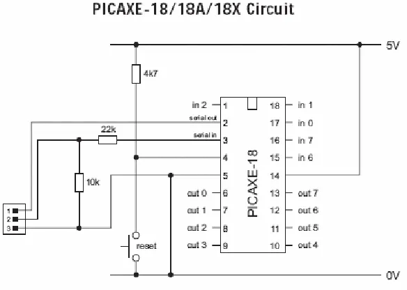
Figure 5.3 PICAXE-18/18A/18X minimum operating circuit Source: http://www.rev-ed.co.uk/docs/picaxe_manual1.pdf
The serial connector was used along with a serial cord to provide an interface between the PICAXE chip and the serial port on a personal computer. This enabled the software on the PC to download programs into the memory of the chip, hence enabling quick program changes. All of the processes needed to set up the circuit, connect the chip to the PC and download a program were simple and very user friendly due to the simplicity of the chip and the software and the extensive documentation that can be found in the users manual. Once the circuit was set up and connected to the power source and the PC, several light emitting diodes were connected to the output pins and a simple program was written to make them flash. This confirmed that the circuit was constructed correctly and all systems were operational.
a very small current passing through the resistor, and therefore the drain on the battery would be minimal. The resistors were connected so that the positive (red) and negative (black) wires were connected to the positive and earth rails that also powered the chip. The signal wire (white) was connected to one of the three pins that support analogue to digital conversion. In this case, pins 0 and 1 were used (see figure 5.3).
When the resistor has a potential difference applied across the positive and ground wires, the potential difference between the signal wire and ground is proportional to the physical position of the shaft around the arc of movement. This is due to another resistor (non variable) built into the body of the potentiometer and wired in series with the variable resistor. It is the varying voltage that results from the interaction between these two resistors that is read into the analogue to digital converter to provide a digital positional reading. In the case of an 8 bit converter, the range of motion of the potentiometer is translated into 256 discrete segments.
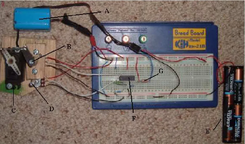
Once the two potentiometers were built into the model, a simple program was written to test the operation of the resistors and the chip. Once everything worked correctly, the servomechanism was added to the system. The 18A chip has a system that allows it to drive servomechanisms that have been designed for radio controlled models, which are also known as ‘servos’. It was decided that to simulate the electrically - actuated hydraulic height control system that is recommended for this design, the best device was a servo mounted beside one of the potentiometers and a linkage mechanism connecting the output shaft on the servo to the input shaft on the potentiometer.
Figure 5.4 Image of the system used to test the operation of the PICAXE chip
When everything is connected correctly, the microcontroller will read in a positional value for each potentiometer, compare the two values, and send a signal to the servomechanism that will turn one of the variable resistors so the physical position of the two resistors match each other to a predetermined level of accuracy, thus achieving the goal of positional control.
5.5 Programming the model
5.6 Description of Program_1
The first approach to programming the PICAXE controller was an attempt to minimise problems caused by the oscillations of the height sensing wheels (both programs can be found in the appendicis). The main function of Label_30, which is repeated every cycle of program operation, is to read the positions of each of the variable resistors into one of the available general purpose byte variables available. The data is read into the RAM using the readadc command. This is repeated with an appropriate time interval until 12 of the 14 byte variables contain height data relating to either the front or the back of the implement frame. In the test program which is designed for the model, two variables are left free in order to store data relating to the position of the servo. Once six height readings from each variable resistor have been gathered, the program calculates an average value of the height of each end of the implement frame. This average value is more useful than a single height value as it minimises the effect of sudden deviations from normal caused by field irregularities.
The time interval between the height measurements can be adjusted to suit the required sensitivity and response time of the system. As the height of the implement is only
corrected once all of the measurements have been collected, a smaller interval between data collection results in an increase in sensitivity and a decrease in response time to genuine lifting or lowering actions. A field that is relatively flat, such as a stone free irrigation paddock, will allow for a shorter interval between measurements. A very rough or stony paddock will require a longer time interval to average out the effects of deviations, and hence increase the response time to lifting and lowering actions.
After the average value has been calculated, the program then calculates which end of the implement is higher by calculating which resistor has the lowest resistance. This action is performed at the end of Label_30 and uses the if- then command as well as the greater than symbol. The syntax used in this program is as follows:
(x and y are height variables, z is the difference in height) if x > y then z = x – y
This ensures a positive z value at all times.
The reason positive values are required is because the byte variables available in the RAM can only store positive numbers between 0 and 255.
Now that the height difference is known, it is necessary to determine if this difference in height is large enough to warrant a correction. This is done by calculating if the height difference falls outside of a tolerance band. The tolerance band is necessary because otherwise constant corrections would take place even if the implement frame is nearly level. The size and even the existence of a tolerance band in the model system is not critical, as the input variable resistor is adjusted by hand to simulate the vertical movement of the three point linkage system. This method of testing will not be able to accurately test the reaction of the system to small random movements that would be encountered in a rough paddock; it will only test the reaction to large, slow movements that would occur during raising and lowering of the implement. The tolerance will be included in the model to make the results from testing the model as useful as possible.
The tolerance band is specified in label_B5, and the code uses three simple let commands to specify the limits of the tolerance band. In this case, it was determined that the height difference value that did not warrant a height adjustment was ± 2 units of height. This corresponds to 2.67 % of the stroke of the servomechanism, as calculated below. Stroke of servo = 150 units
Positional tolerance = ± 2 units = 4 units
Tolerance percentage = (4 / 150) * 100 = 2.67 %
This value was decided upon by what seemed to work, although a wide range of tolerances were tried during testing that did not adversely affect the program. In real life operation, the farmer would adjust this tolerance band to arrive at a balance between the number of adjustments in a certain period of time that are performed and how level the implement is kept.
height value of label_F2 to decrease the height value. The amount of adjustment given changes in proportion to the amount of change needed. For example, in this case, the change in height is defined by the variable B3, so as the difference in height increases, B3 increases. This variable is used in Label_EB and label_F2 where it is added or subtracted from the current servo position to reposition the servo. The servomechanism used in the testing rig requires a pulse ranging in length from 0.75 to 2.25 ms every 20 ms. If the length of any of the input pulses is smaller than 0.75 ms or larger than 2.25 ms, the servo will malfunction. To prevent this from occurring, a min and max command were added to the appropriate labels.
5.7 Testing of Program_1 and Results
The program was loaded onto the PICAXE microcontroller in a variety of configurations. Once a satisfactory base program was written, it was a simple process to experiment with the program constants. As outlined above, the critical constants were the interval between the height data readings and the constant that the height difference is divided by (called c in this case). The interval between data readings was a major problem in the running of this program. Initially, it was thought that the appropriate interval over which the six height readings for each resistor be gathered should be in the order of one or two seconds. A collection time of two seconds results in a time delay between readings of approximately 330 milliseconds, as can be seen in the delays in the code in Label_30. This would eliminate the effects of most of the small, sharp bumps that would be expected in typical operating conditions. It was found that as the servo position is adjusted every time the program cycles, so if the data was collected over a seemingly reasonable two seconds, there would be at least a two second delay between height corrections. This resulted in a very slow and jerky response to any input. This response is far from the smooth and accurate response required from any real system using this technology.
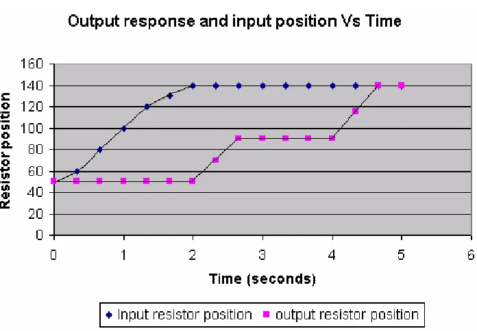
Figure 5.5 is a graphical representation of the system response to an idealised input. The input and outputs were graphed using Microsoft Excel. The response was calculated using a smooth, constant input comparable to the input created when the implement frame is lifted.
The constants used to calculate the response are: Time step = 330 milliseconds
Figure 5.5: Graphical indication of the system response from program_1
Even though figure 5.5 shows an idealised case with no overshoot because the numbers add up to require only two corrections to perfectly reposition the output resistor, a case that would almost never occur in real life, it can be seen that such a program is clearly
unsatisfactory. Even if the speed of the servo was increased, it would still take a minimum of 4.5 seconds to correct for the input. This is clearly too long to wait to level the
implement after it is lifted or lowered. Based on observations of farmers turning on the end of a pass, where the lifting is done as quickly as possible to allow the turning action to occur, the maximum acceptable time delay between a lifting input to the front of the implement and the rear of the implement correcting to match the new height would be approximately 0.5 seconds.
single height value from each of the variable resistors instead of the average of six height values. The program was modified using this method, and is described in the next section.
5.8 Description of Program_2
The second approach to programming the controller utilised the processing of only one height variable per resistor every time the program cycles. It was decided that removing the excess data gathering would greatly increase the cyclic speed of the program, resulting in a smoother, faster and more accurate response. Although various configurations were tried, it was found that the most successful way to write the program was to simply replace the repeated data gathering from Program_1 with a single data collection. As there are now no pauses coded into Label_30, there is no need for the farmer to specify the length of such a pause.
It was found that a pause was needed after each adjustment to allow the servo enough time to reposition. The time needed for repositioning to occur is dependant on the distance needed for the servo to travel to reposition the servo. This distance is dictated by the height difference initially measured that triggered that change. It was decided for this reason that the length of the pause would be based on B3, the variable that determined the initial time response. Thus in Label_F2 and Label_EB a pause was included with a specified length (in milliseconds) of B3. It was found that variable B3 was too small a value to trigger a
sufficient pause. To solve this problem, a multiplier was used before the pause to increase the value of B3. The variable D is used in the appropriate syntax as a multiplier. The appropriate value of D used in the testing was determined using trial and error.
malfunction. To prevent this problem occurring, a constant E was added to the variable b3 to ensure the length of the pause never fell below E milliseconds.
The length of the pause in the model system will be much shorter than the length of the pause required in a real system, as the response speed of a radio controlled
servomechanism is much faster than the response of a large implement. As stated previously, the model varies significantly from the real system, and is only used for proving a concept and testing the limitations of the PICAXE system. As stated previously, the value of each constant will have to be found using trial and error to suit each planting system. Apart from the changes described here, the code of Program_1 is almost identical to the Program_2 code.
The removal of the rolling average means that there is now no way for the program can damp the signal. It is proposed that instead of using software to remove spikes and dips in the signal, all damping should occur before input into the variable resistors. This will require the use of a suitable damper on the frame of the sensing wheel and special attention to the selection of the tyres mounted to the height sensing wheels. The selection of the appropriate damper and tyre is fully explored in the chapter describing the design of the height sensing mechanism.
5.9 Testing of Program_2 and Results
Further investigation into this problem led to the conclusion that the servo did not have enough time to reposition itself in response to a change in input before the program took the next measurement. Another related source of instability was not allowing enough time between servo reposition commands. The addition of variable pauses with a minimum time of E milliseconds in the method described previously seemed to solve the problems
described above.
The values of constants C, D and E determined the response of the test system. The desired response was a smooth, accurate and immediate response with a high level of repeatability. Various values were experimented with to obtain the desired response, and as the PICAXE microprocessor can only process integers, some problems were encountered with finding appropriate values for C and D. However, it was found that when C = 2, D = 3 and E = 30ms, a satisfactory response with the desirable characteristics listed above was delivered by the model.
It is not necessary to provide a graph of input versus output for this case, as when the input resistor is moved at a slow rate of rotation, the servo moves the output resistor with a high degree of accuracy and the response appears to be immediate. Thus a graph of input and output position against time would display very little difference between the two lines. Changing the positional tolerance band has no affect on the running of the program, but as expected, the smaller the tolerance band, the smaller the final difference in height, and the smaller the input needed to provoke a response.
5.10 Relevance of the model
motion in the place of a hydraulic pressure system and an electrically actuated solenoid valve.
When this difference was investigated, it was realised that the main limitation of the PICAXE system is that there is no proportional output available. This means that if the output of the microcontroller was used to operate a solenoid actuated valve, there would be no oil flow to the lift assist system while the program determined that the height difference was within a predetermined tolerance band. When the height difference crept above this threshold, the output pin on the microprocessor would be set from ‘low’ to ‘high’. This would throw the solenoid valve to the fully open position, which would direct the maximum possible flow of hydraulic oil to the lift assist system.
This immediate flow of fluid would correct the height of the implement; however the speed of the lifting or lowering action may be so great that overshoot could occur before the microcontroller can return the valve to the centred position and stop the flow of oil. A system that displays instability in this manner is undesirable, and it is not possible to predict this instability with the model that was constructed.
Another unpredictable element in this design is how the electronic components will be able to withstand the extreme operating conditions that are present on a planting implement. Elements such as vibration, heat, sunlight, dust and even an unreliable electricity source can all cause damage to or affect the performance of electronic equipment. These
CHAPTER 6 - DESIGN OF A HEIGHT SENSING WHEEL
6.1 Design Outline
It is possible to eliminate the electrical system as a method of translating mechanical motion to a solenoid if the electrical system is replaced with a mechanical system that will directly actuate a hydraulic spool valve. It is proposed that this be done to eliminate the many problems that the electrical system presents. The mechanical system will be made in the following way. A height sensing wheel mechanism will be placed at the front and rear of the implement frame. A linkage mechanism will be connected to each wheel mechanism which will translate mechanical movement relating to the vertical movement of the wheel to a common area on the implement.
A device will be designed that will accommodate a hydraulic spool valve and provide the correct motion to both the valve body and the actuation lever. This motion must be such that while the height of the rear sensing wheel is within a specified deviation band of the front sensing wheel, no valve actuation is allowed. When the height of the rear wheel deviates from this band, such as when a lifting action is takes place, the action of the linkages should actuate the valve which will allow oil to flow into the hydraulic rams of the lift assist system. This change of oil volume will correct the height of the rear of the
6.2 Design constraints
There are many issues that need to be addressed if this device is to work effectively. For correct height control, it would be possible to use a different height sensing wheel on each end of the implement, however this would complicate the design of the linkage mechanism to the point where it would be unfeasible. It is proposed that the same sensing mechanism be used on the front and back. This would help with the design of the linkages and will also halve the number of different parts that need to be made to produce the control wheel mechanisms if they are exactly the same.
The entire mechanism will be designed to clamp onto the frame rails of the implement with the use of U-bolts. This means that the different parts of the device can be positioned to suit the layout of the frame and also to avoid clashing with other bolt-on devices such as tines and seed distribution equipment such as distributor heads. To help with possible space constraints, the entire device will be made to be compact. It is not necessary to fully pursue the reduction in size, as the layout of most bolt-on implement devices, especially tines, can be changed to suit the height control device.
This system will be designed to be flexible enough to fit as many implement frames as possible. As everything will be attached with U-bolts, the layout is highly flexible and could be fitted to a wide variety of frames as long as the manufacturer provides linkage arms that are customised to suit the customer’s implement frame geometry. This is because longer implements will require longer linkages than shorter implements. It may be possible to design linkages that are telescopic, so that one device can be adapted to fit any
6.3 Height control wheels
6.3.1 Wheel positioning
It has been determined that the same height sensing mechanism will be used on both the front and the rear of the implement. It is desirable to have the rear wheel trailing behind the implement for simplicity and to keep it out from underneath the frame where it may clash with the tines which sometimes swing backwards to clear obstacles. The front wheel presents a different problem due to the frame geometry. If the front height control wheel trails behind the front frame rail, it will operate underneath the frame. Even though this is the most desirable layout due to simplicity, there is a chance that it will clash with tines and even the frame itself.
Figure 6.1: Image depicting the disadvantage of a trailing front wheel
tractor as close to the rear wheel as possible. This will reduce the error resulting from tractor and implement roll.
To eliminate problems relating to the positioning of the wheel under the frame, it is proposed that the rear wheel will trail, as seen in Figure 6.1, and the front wheel will protrude from the front of the implement, facing the opposite direction to the rear wheel frame. This situation is illustrated in Figure 6.2.
Figure 6.2: Image depicting desired wheel layout
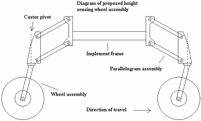
Figure 6.3: Image depicting the final design concept of the wheel frames
This diagram indicates how the vertical movement of the wheels is allowed to occur through the movement of the parallelogram assembly, and the angled axle brace allows the wheels to trail behind the castor pivot regardless of the direction of travel and the
positioning of the mechanism. Note also that this arrangement allows the same components to be used twice, as physically there is no difference between the front and rear control wheels. This helps to keep the cost of production to a minimum and inherent symmetry simplifies the design of the control linkages.
6.4 Design of height sensing wheel
6.4.1 Materials selection
placed upon agricultural equipment. Fatigue resistance is needed to deal with the cyclic loads and vibration that result from travelling across rough ground at moderate speeds. Cost is a major requirement as agricultural machines must be heavily overbuilt to cope with extreme conditions, meaning that much more material is used in the manufacture of the equipment than is needed during normal operation. (Bullock, B. K. 2006, Pers comm. 17 August 2006)
Ease of manufacture is important because complex shapes must be able to be made from the material with a minimum of manpower and machines to reduce costs. High availability is important as much material will be needed to manufacture a large number of these devices, and this will need to be sourced rapidly and effectively. These combined requirements preclude the use of all but one material, which is steel. Steel is the metallic element iron (Fe) that has had the alloying element carbon added during production. Steel is suitable as it is strong, has a high fatigue resistance and can be easily cut to shape with a variety of methods. These shapes can be joined together to form strong parts using
inexpensive welding methods.
6.4.2 Manufacturing method
The wheel mechanism will be designed to fulfil all of the requirements of a height sensing wheel while using a minimum amount of material, while still being easy to manufacture and using sections of readily obtained steel. To make complex shapes, appropriate shapes will be cut from steel plate using either hot gas (usually oxygen/fuel mixture) or laser cutting methods, depending on availability and cost. These shapes will then be welded together, again using the most readily available welding method. Holes that will accommodate shafts will be initially cut with the gas/ laser method and then drilled or reamed out to size to obtain a smooth surface finish and sufficient dimensional accuracy.
Extra support will be given to shafts by welding concentric collars to the plate surface which will increase the surface area of the loaded internal surface, reducing any stress concentrations. These collars will also be used to secure the shafts by drilling small holes through the centre of them at right angles to the shaft axis and corresponding holes through the shafts. Small bolts can then be inserted once the shafts are fitted which after they are fitted with nuts and tightened will secure the shafts in place.
The bearing tube will be of sufficient length to provide a large surface are so bearing pressures are not excessive, keeping wear to a minimum. The proposed pivot system is illustrated in figure 6.4.
Figure 6.4: Diagram of proposed pivot design
6.5 Parallelogram Mechanism
Figure 6.5: Image showing the final parallelogram design
shows the correct setting to suit a (lowered) frame height of 800mm, as may be found on large trailing implements. The large height travel range of the mechanism coupled with the four height settings ensures that this device can be fitted to most three point linkage and trailing implements if this is necessary.
The lower link (D) and upper link (E) are made of 50x63mm RHS with a 3mm wall
thickness. Note that these dimensions correspond to 2 x 2½”, which is a common RHS size. Both are fitted at each end with greasable bearing tubes as described previously that are welded onto the walls of the section. Four of these make up the pivoting points for the mechanism. The upper and lower links are both fitted with 20mm shafts (F and G) that protrude from the links and provide mounting points for the shock absorber (I) and spring mechanism. Item C forms the fourth segment of the parallelogram, and is the part that holds the castor frame which in turn holds the wheel. The castor pivot (H) is made of another greasable bearing tube that is sized to fit a 30mm shaft. Full detail of all of these parts arcan be found in the appendices.
The shock absorber is fitted to the frame to damp excess motion resulting from rough terrain. If this was not done, there would be almost constant activation of the spool valve in even the smoothest terrain, resulting in erratic height control and excess wear of the spool valve and linkages. The shock absorber specified for this application is a unit from the rear of a Nissan Patrol Four wheel drive, part number IA30. This unit was designed for a heavy vehicle, so offers a high amount of energy absorption capacity, as well as a long life and reliability. The stroke of this unit is measured at 230mm, which if the geometry is set correctly is enough for this application.
the damping force by raising the wheel, whereas using the lower bolt holes will reduce the damping force by effectively lowering the wheel.
[image:60.595.144.461.306.711.2]The spring holder works by providing two plates (F and E) that press on either end of the spring and contain it. These plates move relative to each other as the frame moves
vertically, keeping the spring compressed and providing downward force to the wheel. The plates are aligned with a shaft B that is connected to boss assembly G and slides relative to alignment boss A. The sliding shaft is also located coaxially inside the coils of the spring, therefore containing it between the two plates. The alignment boss is held on the upper 20mm shaft by a split pin and a washer (D) instead of a collar and bolt (C). This is because the sliding shaft is too close to the pivot shaft to allow a collar and bolt to be used.
6.6 Spring Design
As the spring holder and the shock absorber share the same mounting points top and bottom, the extension force on the shock absorber during lifting of the implement is equal to the compression force from the spring minus the force that the spring is exerting on the ground through the tyre. The faster the lifting action, the more of the spring’s force is going into extending the shock absorber. Therefore the spring should be able to exert enough force to extend the shock absorber at a fast enough rate to keep up with a rapid lift and provide enough additional force to keep the tyre in contact with the ground at the same time.
This test indicated that a force of 20kg would result in an extension speed of approximately 20mm/second. It is estimated by visual observation that the maximum expected lift rate of a three point linkage implement is approximately 100mm/second. Note that this device is not being customised to fit one tractor; it is designed to be universally used on a wide variety of tractor/implement combinations. Thus the aim of this design process is to come up with a maximum feasible lift rate figure that could be encountered and design a spring that will be able to extend the shock absorber at the correct rate and at the same time supply sufficient force to press the tyre into the ground. Thus based on the observations of the operation of three point linkage systems, it is decided to design the spring to lower the wheel at a rate of 200mm/s. This speed is far greater than any lifting rate that may be encountered, so will be sufficient to keep the wheel pressed into the ground at all times.
At working height which is defined as the height of the implement that forms the
parallelogram into a rectangle (the links are horizontal) it is necessary to find the ratio of change in spring extension to the change in wheel height. This will indicate the speed ratio between the rate of spring extension to the rate at which the wheel changes height. This information is necessary to find how fast the damper should be extended to provide a vertical tyre movement of 200mm/s.
The spring will be designed so the solid length will be met before the shock absorber reaches the end of its stroke to protect the shock absorber from crushing. The figure shown at the left of Figure 6.7 shows an image of the solid model of the parallelogram mechanism positioned at this setting. From measurements taken from the model, this indicates a solid height of 204mm.
Figure 6.7: Image of the parallelogram mechanism at two height extremes
Similar measurements show a fully extended spring height of 413mm. The figure at the right of Figure 6.7 shows the same mechanism in the fully extended state. Thus the spring parameters are now known so an appropriate helical compression spring can be designed.. The spring design process found in Juvinall and Marsheck (1999) will be followed
Spring length (minimum load) = 413mm Solid length = 204mm
Spring length (maximum load) = 10% longer than solid length
= 204 + (204 × 0.1)
= 224.4 mm Minimum load = 294 N
Spring rate = change in load / change in distance = (981-294)/(413-224.4)
= 3.64 N/mm or 3642.6 N/m
Free length = (minimum load / k) + Spring length (minimum load) = (294 / 3.64) + 413
= 493mm
Force required to fully compress the spring (Fs) =
(Free length – spring length (solid)) × k = (493 - 204) × 3.64
= 1052 N
The diameter of the spring as measured at the spring wire axis is the variable that will