University of Southern Queensland Faculty of Engineering and Surveying
DESIGN A PROTOTYPE SOLAR DRYER FOR DRYING SEA
CUCUMBER
A dissertation by
Seini ‘Ela Uatekini Vaipulu
In fulfilment of the requirements of ENG4111/4112 Research Project and Dissertation
Towards the Degree of
Certification of Dissertation
I certify that the ideas, designs and results, analyses and conclusions set out in this dissertation are entirely my own effort, except where otherwise indicated and acknowledged.
I further certify that the work is original and has not been previously submitted for assessment in any other course or institution, except where specifically stated.
Seini Ela Uatekini Vaipulu 0050057964
--- Signature
ACKNOWLEDGEMENT
First and foremost I would like to give thanks and praise to the creator of this universe. Without the Lord all is in vain.
It is a pleasure to express my deep sense of gratitude and indebtedness to my project Supervisor, Dr. Guagnan Chen for his valuable and momentous suggestions and constant advocacy during the course of my project work.
I lovingly place my love and thanks to my beloved husband Amini Vaipulu for his encouragement and support throughout my work and for the completion of this venture. I take this opportunity to thank my family in Tonga for their constant support and for caring my son in Tonga whilst I am here to study. Their help and support is gratefully appreciated. I am much obliged to my friend and fellow agricultural engineer collegue Carmel Rani for all the academic and moral support she gave me throughout the course of this research.
Dedicated to my beloved husband Amini Vaipulu and to
TABLE OF CONTENTS
LIST OF FIGURES ...8 -11
LIST OF TABLES...11
LIST OF MAPS...11
ABSTRACT...12
CHAPTER 1 – Introduction ...13-14
1.1 –Introduction……….131.2– research purpose……….13
1.3– research objectives………14
1.4– conclusion………14
Chapter 2 – literature reviews...15 -66
2.1 – Introduction………..152.2 – Background………15
2.2.1 – History of Solar dryers………..15 2.2.2 – Types of solar dryers………..16-34 2.3 – Design Methodology……….35-43
2.3.1.1 – Solar collectors………..35 -37 2.3.1.2 – Heating Chambers……….37 2.3.1.3 – Fans………..38 -41 2.3.1.4 – Other important components………42-43 2.3.2 – Existing designs………44- 66
Chapter 3 – Availability and suitability of solar dryers in Australia...67 -73
3.1 – Introduction……….67 3.2 – Availability and suitability of Solar dryers in Australia………..67 3.2.1 – solar energy………67 3.2.2 – Australian solar radiation………68- 72 3.2.3 – Australian solar dryer industry……….72 3.3 – Agricultural products suitable for solar drying………72 3.4 – Conclusion………73
Chapter 4 – Case study...74-85
4.1 – Introduction……….74 4.2 – Sea Cucumber………75-85
4.2.3 – Drying Procedure………78- 80 4.3 – Calculations………..81-85
Chapter 5 – Solar dryer Conceptual design...86-91
5.1 – Introduction………..86 5.2 – components………...86-90 5.3 – Performance predictions for the solar dryer design………91
Chapter 6 - Economic analysis of Solar Dryers...92-96
6.1 – Introduction………..92 6.2 – comparison of sun drying versus solar drying……….92- 95 6.3 – cost analysis of solar dryers………...96
Chapter 7 – Conclusion and recommendations
...97-997.1 – Introduction………97 7.2 – Achievement of objectives………..97- 98 7.3 – Recommendations for future Research and work………..99 7.4 – conclusion……….99
References ...100-101
LIST OF FIGURES
1.
Cabinet type dryer for fruit and herbs……….172.
Tent type solar dryer………183.
Shelf type cabinet dryer……….194.
Cabinet dryer with chimney……….205.
Cabinet dryer with chimney with latent heat storage……….216.
Solar tunnel dryer (serial arrangement)………..227.
Solar tunnel dryer (parallel arrangement)………238.
Solar room dryer……….249.
Solar assisted dryer for seeds and herbs……….2610.
Solar assisted dryer containerized version……….2711.
Solar assisted dryer with water type heat storage……….2812.
Simplified schematic of complex, integrated solar drying systems……….2913.
Schematic diagrams of dryers with four cells arrangement………3114.
Solar assisted main dryer with four cells arrangement………3215.
Complex, integrated solar assisted dryer combined with heat pumps………..3316.
Monocrystalline solar panel………3517.
Polycrystalline solar panel………..3619.
Centrifugal fans………3820a. Parrallel fan arrangement………41
20b. Series fan arrangement……….41
21 Vaccum assisted solar dryer………44
22. Schematic diagram of in storage solar drying systems………..45
23. Solar biomass dryer……….45
24a. Schematic view of a solar drier for copra………..46
24b. Sectional view………..46
25. Electrical solar dryers designed by professor Oliver-Barbados………47
26. Dc powered solar dryer designed by Guito Pozzoli-Italy………..48
27. Solar maize dryer………48
28. Natural circulation solar energy cabinet dryer………..49
29. Modified natural circulation solar energy……….50
30. Solar dryer cum water heats………51
31. Fixed bed solar dryer………..52
32. Indirect type natural –circulation solar energy………53
33. Solar cabinet with open cover………..54
34. Radiative – convective dryer………54
35 Boiler solar dryer………..55
36. Fruit and vegetable solar dryer………56
38. Solar dryer use in drying experiments……….58
39. Domestic solar dryer……….58
40. Simple presentation……….59
41. Biomass solar dryer………60
42. Solar grain dryer………60
43. Prototype solar crop dryer………61
44. Compile drying system………61
45. Integrated solar dryer………62
46. Force flow solar dryer……….63
47. Solar assisted forced convection………..64
48. Semi-continuous active mixed-mode type drying………65
49. Roof – integrated solar drying………..65
50. Laboratory solar dryer………66
51. Solar kiln dryer………72
52. Sea cucumber………..76
53. Airflow rate……….81
54. Fan curve………..82
55. 300 Watt solar panel……….87
56. Axial fan for solar dryer……….87
57. Mesh wire……….88
59. Actual Moto solar dryer diagram………90 60. Working Principle of open sun drying ………92
LIST OF TABLES
1. Cost analysis………..96
LIST OF MAPS
Abstract
CHAPTER 1: INTRODUCTION.
This Chapter outlines the background, purpose and objectives of the project as well as providing an introduction into the necessity of the study.
1.1 Introduction.
The processing technologies of many agricultural products are often dedicated and consume a large amount of energy and fuel.
Low-cost solar dryer using renewable solar energy therefore offers the great potential for widespread adoption and application in both the developing countries and in many parts of Australia.
1.2 Project purpose
The present research project aims to develop a small-scale prototype solar dryer for drying and testing of high-value agricultural products, particularly sea cucumber.
This project has significant economic, environmental and social benefits, particularly given the current concern on greenhouse gas emissions of fossil fuels and climate change.
The main research tasks of this project are:
1. Project development and literature review. This chapter will produce an insight into the available solar dryers designs and their limitations.
1.3 Research Objectives
The overall objective of this research project is the conceptual design of the solar dryer for drying agricultural products. In order to accomplish this very important objective there were other objectives that must also be addressed to make it possible for the solar dryer design. These other objectives are:
1. Research published literature on solar drying technology
2. Determine the availability and suitability of solar energy in Australia 3. Identify agricultural products suitable for solar dryers
4. Predict the performance of the proposed design
5. Identify and evaluate the opportunities for further improvements, if time permits.
1.4 Conclusion
CHAPTER 2: LITERATURE REVIEW.
2.1 Introduction
This section comprises of the literature review on studies in the past in relation to solar dryer and present. It also discuss the different types of solar dryers, its advantages and disadvantages, comparison of using open sun drying and solar drying technology.
2.2 – Background
2.2.1 – Background on food drying
Preservation of human and animal food by open-air drying in the sun was presumably one of the first conscious and purposeful technological activities undertaken by humanity (Imre, 1995). Traditional open-air, solar drying methods are based on long term experiences and continue used all over the world to dry plants, seeds, meat, fish, and other agricultural products in order to preserve them.
Over the last few decades, open-air drying has gradually become more and more limited because of the requirements for a large area, the possibilities of quality degradation, pollution from the air, infestation caused by birds and insects, and inherent difficulties in controlling the drying process (Imre, 1993).
Solar drying refers to methods of using the sun’s energy for drying, but excludes open air sun drying.
2.2.2 – Main Types of Solar dryers
According to Baker& Christopher G.J, 1997there are three types of solar dryers and they are classified according to the type of energy used.
Solar natural dryers
Semi-artificial dryers
Solar-assisted dryers
2.2.2.1 - Solar natural dryers. These devices use only ambient energy and have no active elements. The air flow, if there is any, is maintained by natural convection or, in some cases, by thermosyphon effects induced by a chimney.
Solar natural dryers are mainly used as substitutes for traditional open-air drying methods in areas where no other source of energy is available. In contrast to these traditional methods, however, losses and damage to the product caused by rain, dust, insects, birds, and other animals, as well as the pollution from the atmosphere are avoided by the purpose built construction (i.e cabinet and tent type arrangements). Their use results in a better quality product, which should be considered as a positive cash contribution in any economic evaluation.
Types of Solar Natural Dryers
Cabinet type dryers
Figure 1 Cabinet type dryer for fruit and herbs
Simple cabinet dryers consist of a south-facing drying space covered by a transparent material (glass or foil), which also serves as a roof to protect against rain and pollutions. The material to be dried is spread in a thin layer on a tray having a perforated bottom and is directly exposed to the solar radiation. Holes are opened in the lower part of the front wall and in the upper part of the back wall of the cabinet to induce an air flow by natural convection. This carries away the water evaporated from the material and prevents its overheating.
An improved version of the simple cabinet dryer designed for household use is illustrated in Figure 1. The trays with perforated bottoms 1 are arranged under the transparent cover 3, making it possible to dry simultaneously various kinds of foodstuffs, such as fruits, herbs and vegetables. Each product, in its individual tray, may have its own specific drying time. Air, preheated by a black-painted aluminium sheet 4, is introduced into the dryer and regulated by the throttling devices 5 and 6. The open cross-sectional area of the air outlet can gradually be decreased as drying proceeds. At night time, the slide 6 should be closed and the sheet 4 should be fitted to the transparent cover of the cabinet 2.
Figure 2 Tent type solar dryer
(c) Shelf type dryers. Another way to increase the drying capacity, without enlarging the basic surface area, is to employ several trays or shelves, one above the other. Figure 3 illustrates a schematic of a shelf type dyrer (Wibulswas and Niyomkarn, 1980). Thin layers of fruit, vegetable, etc, to be dried are loaded on the perforated shelves partly shade to produce the energy required. Air flow is generated by natural convection through the collector and the material layers on the shelves; moist air leaves the dryer through the upper opening 5.
Figure3 – shelf type cabinet dryer.
Cabinet dryers fitted with a chimney.
The thermosyphon effect required to induce an adequate flow through a solar dryer can be increased by means of a chimney. A simple version of a chimney type solar dryer is presented in Figure 4 (Sunworl, 1980 cited in Baker& Christopher G.J, 1997).
The lower part of the dryer acts as an integrated solar collector with a transparent cover 2; the bottom surface 4 functions as an absorber. Material to be dried is arranged in a static bed. Cover 3 over the bed is also transparent. Chimney 5 is connected to the upper part of the drying space. The technical specifications for a solar rice dryer have been given as (Sunworld, 1980 cited in Baker& Christopher G.J, 1997):
Mass of rice to be dried
, 1000 kg;
Bed thickness, 0.1 m;
Collector surface area, 23 m²;
Height of the chimney, 5 m;
Figure 4 – cabinet dryers with chimney
Cabinet dryers fitted with a chimney and heat storage
To extend the drying process into the non-sunny hours of the day, heat storage should be employed. Water vessels have been used as a relatively low cost means of heat storage (Puigalli and Lara, 1982 cited in Baker& Christopher G.J, 1997).
trays can be exchanged during drying to equalize differences in drying rates. The air flow rate through cabinet dryers fitted with a chimney can also be enhanced by using a wind-driven ventilator connected to the upper end of the chimney (Bansal and Geroge, 1993 cited in Baker and Christopher G J, 1997).
Figure 5 – cabinet dryer with chimney with latent heat storage.
2.2.2.2 -
Semi-artificial solar dryer
. These usually
feature a solar collector and a fan for maintaining a special air flow through the drying space. In the case of directly irradiated solar tunnel dryers, a section of the tunnel may be employed as a transparent plastic covered solar collector (Imre, 1989, 1995; Lutz and Muhlbauer, 1986 cited in Baker& Christopher G.J, 1997).Types of Semi-artificial solar dryers
Solar tunnel dryers
Solar tunnel dryers are frequently used for drying agricultural products (Imre, 1986a, 1995; Lutz and Muhlbauer, 1986; Esper and Muhlbauer, 1993; Bansal and George, 1993 cited in Baker & Christopher G J, 1997). Figure 6 shows a simplified arrangement of a serial solar tunnel located on the ground. The required mass flow rate of air is blown into the tunnel by means of a fan. The tunnel has a transparent covering. The first section serves as a solar collector with a black-bottomed surface for preheating the air. The connecting section of the tunnel forms the drying space. Material to be dried is spread on the bottom and is directly irradiated by the sun.
Figure 6 – solar tunnel dryer (serial arrangement)
The length of the solar tunnel dryer can be reduced by arranging the collector and the drying section in parallel (Fig 7a). The fan is driven by an electric motor connected to the grid or fed by electricity generated by solar photovoltaic or wind-driven equipment. The cross-section of the dryer is shown in Figure 7b. A transparent-foil covering sheet is held in place by springs and black foil is used as an absorber and as the bed surface of the material to be dried. Structural elements are supported on concrete foundations.
the dryer may be adapted to the drying capacity required. For tropical use, a biomass assisted version of the solar tunnel dryer has been developed.
The cross-section of the tunnel may be triangular, semi-circular, or have a flat cover (Muhlbauer et al., 1993; Janjal and Hirunlabh, 1993 cited in Baker & Christopher G J, 1997). A curved or semi-circular shaped cross-section is generally used in the case of serial collector-dryer arrangement.
Fig 7 Solar tunnel dryer (parallel arrangement).
Greenhouse-type solar dryers
Foil-covered tunnel type greenhouses can also be used for drying agricultural products (Bansal and George, 1993; Reuss, 1993; Muhlbauer et al., 1993 cited in Baker & Christopher G J, 1997). They always incorporate a fan for maintaining a continuous flow of air, which is sometimes partially recirculated. Where sensitive materials are dried, some kind of shading is needed is moved through the drying space on a belt or a conveyor.
Solar room dryers
For drying agricultural products in larger quantities (e.g. grains, folder), solar room dryers with a static bed are used successfully (Dernedde and Peters, 1978; Wieneke, 1980; Imre, 1995 cited in Baker & Christopher G J, 1997).
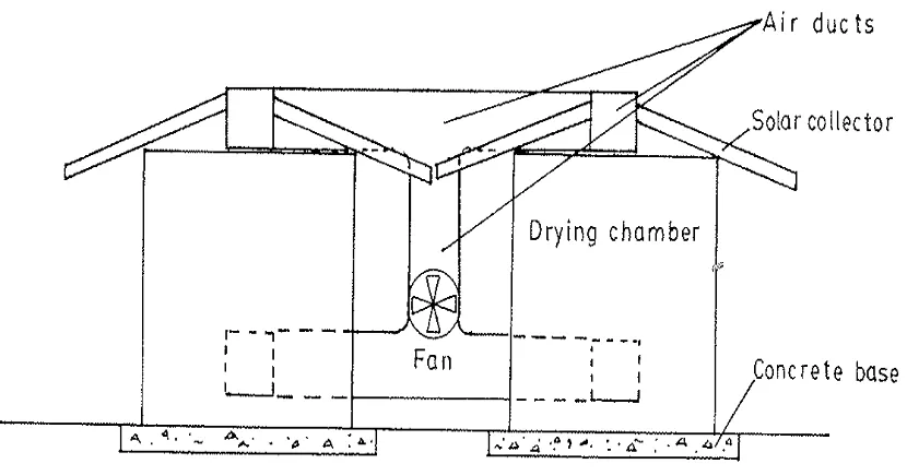
Figure 8 represents a typical solar room dryer. Air flow through the bed 1 is maintained by a fan 3 selected according to the flow resistance of the material layer. The bottom of the bed is perforated and air is blown into the distribution space beneath it. Preheating of the air occurs in the roof integrated solar collector 2, using the roof cover as heat absorber. Atmosphere air, entering through the inlet 4, can be mixed with preheated air to control the inlet air temperature if required. Moist air leaves room through the air outlets arranged on the side walls. For emergencies situations, such as bad weather conditions, a simple auxiliary gas operated air heater can be connected to the suction side 4 of the fan. Solar room dryers with roof integrated collectors have also been used successfully for drying fruits such as peanuts and bananas (Vaughan and Lambert, 1980; Bowrey et al., 1980 sited in Baker & Christopher G J, 1997).
Figure8 – solar room dryer
Types of Solar- assisted dryers
Solar-assisted dryers are conventional dryers to which supplementary equipment is added to enable a significant proportion of the thermal energy required for drying to be replaced by solar energy. In these types of dryer, a planned, and generally optimized drying process can be achieve to obtain superior product quality and good economic performance of the dryer can be eliminated by using an independent energy source, if needed, and proper control facilities.
Solar-assisted dryer for seeds and herbs
In Fig 9, the ground plan and the cross-section of the dryer are presented (Imre, 1986a, 1995; Imre et al., 1986a; Catalogue, 1986). For economic reasons, the drying space is divided into two cells. Each cell has its own individual 2-speed fan 3. Fans are arranged in separate chambers 9. The conventional energy source of the dryer, a burner 4 fuelled by natural gas, is situated in chamber 10.
An uncovered air-collector 2, integrated into the roof structure, is used to convert the solar radiation into thermal energy. The conventional roof covering, made of trapezoidal galvanized steel blades 8 with black-painted surfaces, serves as heat absorber. A continuous covering of monolith plates 17, mounted at an appropriate distance beneath the absorber, forms of air ducts 19 between the rafters 18. These ducts 19 connect into a distribution channel 11 located in the ceiling sections of chambers 20. In this way, the total air flow through the collector can be shared between the fan chambers when valve 13 is open. Fans 3 blow the air into the drying cells. Thermo generator 4 moves the heated air into the fan ducts in the required ration through ducts 16, when required.
Figure.9 – solar assisted dryers for seeds and herbs
In Figure 10, a schematic diagram of the containerized version of the dryer is shown. For fragile materials that may be subject to damage during handling, the use of containers with perforated bottoms 21 is preferred. These are placed on foot stools with proper air stuffing 22 between them.
The main technical specifications for a seeds dryer are (Catalogue, 1986);
Effective surface area of one cell, 56 m²;
Dry mass of seed in one cell, 5600 kg;
Mass flow rate of air (one fan), at 1090 rpm, 41 000 m³ h¯¹
at 475 rpm, 21500 m³ h¯¹;
Surface area of the collector field, 191 m²;
Output of the thermogenerator, 93 kW.
can be distributed between the cells according to actual need and can be used more effectively in the dryer by reducing the exit losses, especially in the falling-rate drying period. The fans are rated according to the layer thickness employed in the beds and the air inlet temperature required; the fan should be operated at the lower rpm when higher temperatures are needed.
Figure 10 – solar assisted dryer containerized version
Solar-assisted dryers with heat storage
Connecting physical heat storage equipment to solar dryers is justified by three main reasons
The daily drying time can be extended to those hours of the day when the sun does not shine
Overdrying can be prevented by storing the surplus solar energy collected in the peak radiation periods
The inlet temperature of the drying air can be controlled
(a) Solar-assisted dryers with heat storage. Figure 11 depicts a solar-assisted dryer with water heat storage (Auer, 1980). The working fluid of the solar collector 1 is water, circulated by pump 2 along the pipe 3. The heated water flows to the heat storage tank 4. Atmosphere air is drawn by fan 7 through the water-air heat exchanger 5. The primary working heat exchange medium is the water circulated by pump 6 from the heat storage tank 4. An auxiliary air heater 8 can be used if required to maintain the prescribed inlet air temperature. Material to ne dried is arranged in a static bed 9.
Figure 11 Solar assisted dryer with water type heat storage.
the same times, the conventional energy source of the HWS can be used as the auxiliary heater for the solar dryer.
Figure 12 illustrates a complex, integrated high performance solar dryer (Imre, 1986, 1989, 1995; Imre et al., 1986b, 1991 cited in Baker & Christopher G J, 1997). It was designed to produce dried lucerne hay for dairy farming. During idle periods, the system produces hot water for technological purposes. The drying space is arranged in a barn, which also serves for storing the dried hay. The single-glazed solar flat-plate collector is integral with the roof structure. It can be connected to the water-air heat exchanger of the dryer and to the hot water tank serving as the heat storage vessels by proper manipulating of valves 1 to 4. The available drying space in the barn is divided into four cells (Figure 13(Imre, 1989 cited in Baker & Christopher G J, 1997)). Each cell has its own fan and water-air heat exchanger. Hot water produced by the solar collector can be distributed at will between the cells. Auxiliary energy is provided by gas operated thermo generators. For emergency situations, electrical heating is built into the tank. This can also be used as an additional auxiliary energy source. The principal system specifications are (Imre et al., 1986b cited in Baker & Christopher G J, 1997).
Figure 12 – simplified schematic of complex, integrated solar drying systems
Solar flat-plate collector
Maximum volumetric flow rate of the working fluid, 15.6 m³ h¯¹
Dryer
System, static bed dryer; area, 800 m²
Number of drying spaces (cells), four (200 m² each) Total layer thickness, 6 m
Annual quantity of dried material, 1000 t Storage capacity, 700 t
Air System
Indirect, preheating the air by water-air exchangers
Number of fans, four (one fan per cell). Air flow rate per fan, 106000 m³ h¯¹ Primary auxiliary energy sources, biogas generations
Storage tank
Volume, 100 m² System, stratified
Figure 13 – Schematic of dryers with four cells arrangement.
Solar-assisted dryers with rock bed heat storage
In solar-assisted direct type dryers, rock bed, gravel bed and pebble bed heat storage systems are frequently used (Auer, 1980; Read et al., 1974; Contier and Farber, 1982; Niles et al., 1978; Choudhury et al., 1995 cited in Baker & Christopher G J, 1997).
A high performance raisin dryer featuring a gravel bed storage system is shown in Figure 14. The collector field1 of 1812 m² surface area is located on the ground. Fresh air is blown through the collector loop by the fan 10 connected to a heat recovery unit 9 (dampers 4B and 5B are closed). Air, preheated in the collector, flows in the air duct 11 to the location where the gas burner 6 situated. The burner serves as auxiliary heater and operates when the temperature of the air arriving from the collector is lower than required. Warm air is transported into the drying tunnel 8 by the fan 7. Moist air leaves the dryer through the heat recovery unit 9. The rock bed heat store 3 can be charged by the collector when the fan 2 is in operation and air valves 4A and 5A are closed.
Figure 14 – Solar assisted main dryers with rock – bed heat storage
Solar-assisted dryer combined with absorbent units
Complex and integrated solar- assisted dryers can be combined with absorbent beds, which may serve for energy storage as wee as for auxiliary heating (Imre et al., 1982; Twidell et al., 1993; Imre, 1995 cited in Baker & Christopher G J, 1997). The energy storage capacity of an absorbent (e.g.zeolite or silica gel) is partly attributable to sensible heat and partly to moisture absorptions. The specific total energy capacity is about an order of magnitude than that of a physical heat store.
The dynamic adsorption capacity of the subsoilers should be exploited by regeneration at a temperature normally exceeding 150°C. However a considerable part of the energy used for regeneration can also be used for other purposes, eg. for hot water production. When solar energy is not available, the adsorption capacity can be used to operate the dryer.
Solar dryers fitted with adsorbent units have proved to be economically competitive with that incorporating rock bed energy storage. However, the economic comparison is greatly influenced by the local condition, opportunities and requirements (Imre,1974; Close and Dunkle,1977;Pinaga at el, 1981 cited in Baker & Christopher G J, 1997).
Solar – assisted dryers combined with heat pumps.
latent heat by cooling the air and condensing its water vapour content. This could be achieved by using a heat pump connected to the air outlet of the dryer.
Figure 15 illustrates the construction of a complex integrated solar lucerne dryer combined with a heat pump (Imre et al, 1982, Imre,1995 cited in Baker & Christopher G J, 1997). Moist air flows from the dryer 7 to the evaporator 9 of the heat pump. Here the air is cooled and moisture condenses. This provides the latent heat required to evaporate the working fluid of the heat pump, which circulates through the compressor 10, the condenser 11, the expansion valve 12, and back to the evaporator. Cold water is heated in the condenser 11 and fed the water heat storage tank and depending upon the ambient conditions, air leaving the evaporator 9 can be recirculated to the dryer heat exchanger6. Solar assisted drying equipment combined with a heat pump an heat storage has been developed for drying peanuts (Auer, 1980 cited in Baker & Christopher G J, 1997).
2.2.3 – ADVANTAGES AND LIMITATIONS OF DIFFERENT TYPES OF SOLAR DRYERS.
Advantages of solar natural driers
1. Low investments, as compared to mechanical dryers 2. Minimize the problems associated with open sun drying 3. A variety of solar natural driers are available worldwide.
Limitations
1. Due to its small capacity is use to small scale applications 2. Discoloration of crop due to direct exposure to solar radiation 3. Moisture condensation inside glass covers reducing its transitivity.
4. Sometimes the insufficient rise in crop temperature affecting moisture removes 5. Limited use of selective coatings on the absorber plate.
Advantage of Semi artificial assisted driers
1. Can be used to drying agricultural products in such as fruits, crops, vegetables , herbs, coffee, cocoa and coconuts
2. Relatively cheap in terms of construction
3. Reliable when compared with solar natural driers.
Limitations
1. Cannot be used to dry agricultural products in large quantity.
Advantages of solar assisted dryer
1. Most suitable for drying large quantity of agricultural products 2. It’s designs are economical in the sense of drying space.
Limitations
1. Expensive because of the components that deals with the designs.
3. Costly to use for small scale drying
2.3 – Design Methodology.
The design methodology section comprises of the components of solar dryers designs and how to get the best performance from it.
2.3.1 – solar dryer components 2.3.1.1 – solar collectors
Three types of solar panels
1. Monocrystalline Solar Panels
Figure16 – Monocrystalline solar panel
2. Polycrystalline Solar Panels
Figure 17 – Polycrystalline solar panel
Polycrystalline solar panels are the most common type of solar panels on the market today. They look a lot like shattered glass. They are slightly less efficient then the monocrystalline solar panels and less expensive to produce. Instead of one large crystal, this type of solar panel consists of multiple amounts of smaller silicon crystals.
3. Amorphous Solar Panels
Figure 18 – Amorphous solar panel
Solar Panel Efficiency
Solar Panel efficiency is the percentage of solar energy that is captured and converted into electricity. It's difficult to give an exact number, so the numbers below are an average percentage of efficiency that the different types of solar panels output. Thin film solar panels will generally degrade approximately 1% each year, whereas crystalline panels degrade at approximately .5%. Below are the approximate percentages for each type of solarpanel
Monocrystalline-18% Polycrystalline-15%
Amorphous (thin-film)- 10% 2.3.1.2 – Heating chambers
The heating chamber can in any shape and size but it should have the following characteristic in order to increase its efficiency
a. Should have an appropriate size for its projected use.
b. Should be of a convenient height.
2.3.1.3 – Fans
Fan Types
Most fans can be categorized as either axial-flow or centrifugal (see Figure 3). Axial-flow fans are sometimes called propeller fans, although that's really just one type of axial-flow fan. Air moves in a straight line through axial-flow fans parallel to the axis or impeller shaft. The impeller has a number of blades attached to a central hub.
Figure 3. Types of fans used for ventilating crops.
Axial-Flow Fans
Centrifugal Fans
Figure 19a – 19b – a. axial fan, b. centrifugal fan
or both ends of the impeller parallel to the shaft and exits one side perpendicular to the shaft. The blades can be straight, slanted in the direction of airflow (forward-curved), or slanted opposite the airflow direction (backward-curved or backward-inclined).
Propeller Fans (panel fans)
These are axial-flow type fans that have from two to about seven long blades attached to a small hub. Fan diameter is usually large relative to the fan's length or thickness. Some propeller fans are called panel fans and are designed for mounting in a wall or plenum divider. Some are belt-driven and some have the impeller hub attached directly to the motor shaft (direct-driven).
Propeller fans normally can't generate more than about 2 in. water pressure. They are most commonly used for potato ventilation, forced-air produce cooling, hay drying, exhausting air from attics or overhead spaces, or general air circulation. They are seldom used for grain drying or aeration.
Tube-axial, vane-axial
These axial-flow fans have a barrel-shaped housing and an impeller that has a large hub with a number of short blades attached to it. They are generally direct-driven and the motor is cooled by the airstream. In positive pressure systems, the air stream captures the waste heat given off by the motor. Vane-axial fans have guide vanes inside the fan housing to help reduce air turbulence.
Tube-axial and vane-axial fans are the most common types used for grain drying and aeration. They are relatively inexpensive and fairly efficient when static pressure is less than about 4 in. water. The main disadvantage of these fans is that they are very noisy.
Centrifugal
efficient type of fan when static pressure is greater than about 4 in. water. The motor on centrifugal fans is normally outside the air stream; you need to install a special housing around the motor if you want to capture the heat it gives off.
Forced-air heating and ventilating systems often use centrifugal fans that have forward-curved blades. Motors on these fans can be overloaded and burn out when the fans are operated outside certain pressure ranges. This characteristic makes them unsuitable for many crop drying and storage applications.
In-line centrifugal
These fans have axial airflow, but use a centrifugal-type impeller. Price and operating characteristics are between those of backward-inclined centrifugal and tube-axial fans.
Multiple Fans
It is sometimes necessary or desirable to install more than one fan to provide air to a common plenum or supply manifold for a duct system. Fans can be arranged in parallel or series (Figure 4). Reasons for using multiple fans include:
Total airflow, pressure, or power requirements exceed the capabilities of the largest fan available from your dealer.
The starting current for a single large fan motor is greater than the electrical system can handle. The maximum starting current is lower if several small fans are started one at a time.
When multiple fans are installed, you have the option of turning some of the fans off and operating with a lower airflow when conditions allow.
Figure 20 – Parallel and series Parallel
Parallel arrangement means fans are installed side-by-side or at several points along a manifold or plenum. The most common applications are where total airflow requirement is large, but pressure is moderate. When fans are installed in parallel, they all face the same pressure. Total airflow is estimated by adding the airflow provided by each fan at the expected pressure.
Series
2.3.1.4 – other components
a. Drying trays
The drying trays should have the following characteristic
1. Make them strong enough to withstand vigorous cleaning as well as the weight of food. 2. Use a material that will allow good circulation of air through the tray.
3. Make them of a non-toxic material (don't use galvanized or aluminum tray material). 4. Design them to easily fit into the dryer.
5. Space them at least 5 cm. apart.
b. Vents
Characteristic of a good vent :
1. Maximize the difference in height between the inlet and cutlet vents.
2. Maximize the width of both vents. In a cabinet dryer, make both vents 1/3 the area of the back wall.
3. Insect-proof the vent openings with screen or netting.
4. Make a door over the bottom vent that hinges from the top side. 5. Make a door over the top vent that hinges from the bottom. 6. Make both doors sealable against night air.
7. Devise a way to maintain the vent doors open at different angles.
c. Access Door
1. Should be large enough for easy access to all the trays. 2. Should hinge either from the side or bottom
3. Should be insect-proof when closed.
d. Glazing
1.Must be transparent.
3. Should be considered as far as its: cost strength thickness ease of installation 4. Should have the correct compass orientation if built in place.
5. Should have the correct angle according to the time of year it will be used. (For summer: Latitude -109; winter: Latitude +30 Q; spring, fall and year round: Latitude +10 ºC.)
e. Solar Preheater
1. Inlet and outlet vents should be of the same size as the ones on the dryer. 2. Glazing angle may be different from the one on the dryer to maximize use throughout the year.
3. The absorber surface on the bottom of the preheater should be a dark color, and preferably made of metal.
2.3.2 – EXISTING DESIGNS FOR DIFFERENT TYPES OF SOLAR DRYERS.
This part will discuss some of the existing solar dryers designs. There are so many designs found throughout the course of this research and therefore only a few designs will be mentioned.
1. Vacuum assister solar dryer
According to (Raijkumar. P et al. 2006) this drying unit consists of a drying chamber (polycarbonate vaccum bell) measuring 25.4cm height and 19cm diameter, a circular disc fitted with weighing platform, polyethylene gasket, temperature probe and vacuum pump. The polyethylene gasket was kept in between the drying chamber and circular disc to avoid leakage of air.
Figure 21– Vacuum assisted solar dryer.
2. In – storage solar drying systems
Figure 22 – Schematic diagram of in storage solar drying systems 3. Solar – Biomass Dryer.
[image:45.595.133.477.90.310.2]The solar biomass dryer has 3 major components which are drying chamber, solar collector and a biomass furnace (Arnold R et al. 2001).
4. Solar dyers design for drying copra (M.Moharaj & P.Chadrasejkar, 2008).
Figure 24a) – schematic view of a solar drier for copra
[image:46.595.122.432.130.414.2]5. Electrical Solar Dryer – AC Powered
6. Solar dryer – DC powered.
[image:48.595.112.421.171.476.2]The dyer consists of sun collector panel, drying chamber, fan for air circulation, moisture and temperature sensor and PV-panel for powering the fan.
Figure 27 - A distributed – type natural-circulation solar Maize dryer designed by Othieno, Graiger and Twidell.
8. Natural –circulation solar-energy cabinet dryer with chimney.
[image:49.595.74.505.234.477.2]9. Modified natural-circulation solar-energy cabinet dryer.
10.Solar dryer cum water heater
[image:51.595.89.507.175.477.2]
11.Fixed bed solar dryer
12.Indirect type natural –circulation solar-energy dryer
13.Solar Cabinet with open cover
Figure 33 - Ampratevum developed a solar collector in the form of a prototype solar cabinet dryer in Oman.
[image:54.595.110.542.113.402.2]Figure 34 - Nijimeh et. Al studied the drying behaviour of food waste for utilisation of animal feeds thru the two solar dryers manufactured from locally available materials (For radiative and boiler dryer).
[image:55.595.111.500.227.489.2]15.Boiler Solar dryer
16.Fruit and Vegetable solar dryer
[image:56.595.91.435.143.468.2]
17.Portable farm solar dryer
Figure 37 - Singh et.al developed a solar dryer to enable Indian farmers to add values to their produce by drying it at farm itself.
18.Solar dryer used in drying experiments- pictorial view and cross sectional view
[image:57.595.124.562.144.429.2]19.Domestic solar dryer
[image:58.595.97.518.151.400.2]20.Simple Presentation MI
[image:59.595.110.526.149.417.2]21.Biomass solar dryer
Figure 42 - Mumba designed and developed a solar grain dryer with photovoltaic powered air circulation.
23.Prototype solar dryer
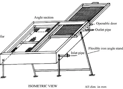
Figure 43 - Thoruwa et.al designed and developed a prototype solar crop dryer.
[image:61.595.116.558.556.766.2]Figure 44 -Sarsilmaz et.al conducted experiments on drying of apricots in a newly developed rotary column cylindrical dryer.
25.Intergrated solar dryer
[image:62.595.115.561.196.489.2]26.Force flow solar dryer
27.Solar-assisted forced convection
28.Semi-continuous active mixed – mode type drying
Figure 48 - Zomorodian et.al introduced a new approach for employing solar radiation as the main source of energy.
29.Roof – intergrated solar drying
[image:65.595.105.541.495.716.2]30.Laboratory solar dryer
[image:66.595.110.564.118.434.2]Chapter 3 – Availability and suitability of solar dryers
in Australia.
3.1– Introduction
This chapter will discuss the suitability of solar dryers here in Australia in terms of the solar radiation it produces per day. Not only that but it will also discuss the availability of solar dryers in terms of companies here that manufactures them. It will also include a list of agricultural products that are suitable to be dried using solar dryers.
3.2– Availability and suitability of solar dryers in Australia.
3.2.1 – Solar Energy.
Solar energy is energy from the sun. This energy drives the climate and weather and supports virtually all life on Earth.
3.2.2– Australian solar radiation.
Solar power is a clean energy source, which is very accessible in Australia, due to the
amount of open plains and sunlight that the country get each day. Australia has a very
suitable climate for solar energy with most of our nation desert and very arid and having
80% of the land experiencing less than 600 millimetres of rainfall per year. The land is also
very flat, making Australia extremely suitable for solar power.
The amount of solar radiation in Mega Joules per square metre per day and annually is
depicted in maps 1 and 2. The average output of energy per day for Queensland per day is
approximately 6-27Megajoules per square meter and annually it is 15-24Megajoules per
square meter.
It is also noted in Map 3 the amount of sunshine hours obtained, again for Queensland is
between 6 to 9 hours of sunshine. Clearly there is abundance of solar energy and sunshine
Map 2 – Daily solar exposure
Map 3 – Average annual daily sunshine hours Source:
3.2.3– Australian solar Dryers Industries
Throughout this research there has been one solar dryer company here in Australia that manufactures Solar Dryers. This company is called Solar Dryers Australia and it is a completely Australian owned and operated company with a major environmental focus.
sizes are 10m3, 20m3, 30m3, 50m3, 75m3 and 100m3 and are custom design for specific requirements.
Figure 51 - picture of solar kiln dryer designed by Solar dryers Australia Ltd.
3.3
– Agricultural products suitable for solar dryers
Solar dryers are perfectly acceptable for use in the drying process. The agricultural products suitable for drying using the solar dryer are as follows:
1. Fruits
2. Vegetables
3. Crops
4. Fish
5. Sea Food
6. Grains
7. Nuts
8. Herbs n spices
3.4- Conclusion
Chapter 4 – Case study
4.1 – Introduction
This chapter comprises of information related to the product dried. Sea cucumber is the product chosen for this case study, therefore there will be background information related to its initial and final moisture content after being dried, drying methods and its density. In this case study 1000Kg of Sea Cucumber needs to be dried using the conceptual solar dryer in half or more than half the drying time it takes using open sun drying. The traditional sun drying take up to two weeks but in this case study the drying time should only be in approximately 2 days with 8 hours sunshine hours. The other task in this chapter is to calculate the followings:
The amount of water evaporated from the Sea Cucumber in order to get the final moisture content after drying
Drying time required for drying using the solar dryer
Fan air flow rate
Fan Power
The amount of heat required
The amount of moisture removed per hour
4.2 – Sea cucumber
4.2.1 – Background information
Sea cucumbers (Holothurians) are echinoderms—like starfish and sea urchins. There are some 1,250 known species, and many of these animals are indeed shaped like soft-bodied cucumbers. All sea cucumbers are ocean dwellers, though some inhabit the shallows and others live in the deep ocean. They live on or near the ocean floor—sometimes partially buried beneath it.
Sea cucumbers are traditionally consumed raw, dried and boiled as food for human consumption in many tropical and sub-tropical countries. Major consuming countries are China, Hong Kong, South Korea, Singapore, and Japan. The dried product is called beche-der-mer in French, hai-som in Chinese, and trepan in Indonesia. (reference Effect and handling of Procedure on the chemical compostion of sea cucumber, Nil Pembe Ozer, suhendan Mol and Candan Varlik.)
Figure 52- Picture of different sea cucumber species
4.2.2 – Moisture Contents
The initial moisture content of fresh sea cucumber is found to be 85% and must be dried to 10% or 6.5% moisture content.
4.2.3 – Sea cucumber’s density.
Broad-scale distribution and density data of sea cucumber inhabiting Ningaloo Reef, Western Australia (WA), are compared with published data from Ashmore Reef, Cartier Reef and Rowley Shoals, northern WA. Results are presented particularly of the black teatfish,
Holothuria (Microthele) nobilis. Heavy fishing pressure has affected numbers of H. nobilis on both Ashmore and Cartier Reefs, where population densities of less than 1.0 in ha-1 have been recorded. Rowley Shoals and Ningaloo Reef, areas that are unlikely to have experienced significant fishing pressure, support black teatfish densities of 9.1 and 19.3-27.2 ind ha-1, respectively. Densities of black teatfish recorded at Coral Bay are approximately equal to or exceed those reported on reefs that are closed to fishing on the Great Barrier Reef.
lagoon. H. atra showed little or no recognisable pattern of distribution. Studies utilising GIS are currently determining the relationship between species distribution and physical habitat characteristics. This process ultimately will help clarify the micro-habitat characteristics of coral reef holothurians. Methods associated with this technique are described.
4.2.4 – Drying Sea cucumber
The Procedure
The procedure is simple but must be carried out with care if good - quality products are to be obtained.
Boiling is the most important step in processing. Incorrect cooking can irreversibly damage the product by causing splitting of the skin or other faults that will only show up at the drying stage.
1. First Boil
Fill the container with clean sea water and bring it to the boil. It is very important to bring the water to the boil before adding the live sea cucumber to the container. Sort the sea cucumber according to size. Only boil those of similar size together, as the cooking time needed varies according to size. If the sea cucumber have been kept in seawater for some time, allow them to naturally evacuate any internal water. Gently squeezing the body to assist this process. Immediately put the animal into the boiling water one by one while stirring, making sure that each one is completely covered with water. Do not allow any to remain partly out of the water as the skin could split. To ensure uniform heating do not put too many animals into the water at once.
2. Piercing the body wall during the first boil (optional)
The procedure releases the build –up of pressure caused by too much water and air inside the cooking animal. Make a short longitudinal slit about 4 cm long, along the center line of the back, to let the water out.
After piercing continue to boil for about another 10 -15 minutes. Continue to stir gently and frequently, to ensure uniform cooking. When the ends of the sea cucumber become rubber ball, the first boiling is complete. This will not be hard to recognise. Remove the cooked sea cucumber from the container and immerse them in fresh seawater to cool down.
3. Slitting and removal of the gut
Make a straight slit down the centre line of the animal to within 3cm of each end, incorporating the cut made during the first boiling. Open up the beche-de-mer and empty out the loose gut contents. Cut out the organs that run through the centre, removing the anal teeth and any loose tissue, using the hands only. Do not remove the strips of tissue running down the length of the inner walls of the body cavity (the longitudinal muscle bands). Wash out with clean sea water.
4. Second boil
Follow the same procedure as for the first boil. Cook for 15 -40 minutes, stirring continuously. Exact boiling time again depend on the size of the animal. The sea cucumber will shrink slightly and gradually become hard. This hardness is the best way to gauge cooking time, so inspect them frequently. Check the cut edge of the animal too; if it no longer feels slimy, but rather dry rubbery, the second boiling is complete. Remove the sea cucumbers quickly from the container and put them into cold seawater to cool. They are now ready for smoke-drying or sun drying.
5. Smoke drying
The fire should be small, producing constant heat. If the fire is too hot, it will overcook sea cucumbers, reducing their value. The fire should therefore be tended regularly.
Do not turn them over during smoking – always leave a split side facing down. Place the cooked sea cucumber on the trays of small ones at the top and the larger ones at the bottom closer to the fire.
Periodically rotate the trays around in the dryer. Move the tray on the bottom rung to the top rung. This ensures uniform drying.
The sticks holding open the long slits should be removed about half-way through the drying process, when insides of the animal feel dry to the touch. The sea cucumbers can now be tied up with a string or vines to help close up the slits edges, especially if they are misshapen.
6. Sun curing
Brush off any shoot, ash or dirt that has accumulated during the smoking. Place the product in the sun on a clean, dry surface. It is preferable to use drying racks for sun- curing because the product can then dry on both sides simultaneously. These are simply wood – framed tables with a fixed mesh top (chicken wire, steel mesh, plastic mesh or fishing nets). Alternatively, mesh trays similar to the ones used in the smoker, can be placed directly onto the table frame.
Curing can take as few as four of five days, or as long as one to two weeks, depending on the size of the species of sea cucumber, and of course, the weather. It is important to avoid exposing the product to the rain at any time – contact with fresh water is not good for it. Use plastic sheets to cover the curing product if rain threatens, or, if using trays move them indoors. When sun-curing is complete, a powdery substance will appear on the surface of the beche-de-mer.
4.3 - Calculations
1. Calculating the airflow rate required for the solar dryer fan.
Figure 53- air flow diagram
Assume that the airflow is 1m/s Area of drying area = 1m2
Airflow rate = 2m2 x 1m/s
Fan Curve
Figure 54 – Fan curve
The red line in the above diagram refers to measurements in this particular example.
At 350 rpm and a airflow rate of 2118.9 CFM the static pressure (in.water) = 2inches
Fan Power = airflow rate x static pressure (in.water)/3814
2. Calculating the Mass of water to be lost from the product.
In this case study 1000kg of sea cucumber will be dried in one load using the conceptual solar dryer. It is important to find out the mass of the water that has to taken out from the sea cucumber in order for the sea cucumber to reach its dried moisture content.
The equation used is
Mw = Mc [(Wi – Wf)/ (100-Wf)] where
Mw = Mass of water loss
Mc = Mass of product to be dried Wi = initial moisture content Wf = final moisture content
The initial moisture content of sea cucumber is 85% but in this calculation the initial moisture content will be 35. The reason is that from after the cooking for 2 times the moisture content will decrease.
Mw = Mc [(Wi – Wf)/ (100 – Wf)
3. Calculating the mass flow rate of air.
Assumptions
Drying temperature in the dryer = 43.3°C
Ambient condition = 29.4°C dry bulb
Ambient condition = 21.1°C wet bulb Relative humidity = 85%
From the calculation in 1 we know that the airflow rate is 1m3/s or 2118.9 CFM (cubic foot per minute) or 7200m3/h.
The specific volume for this calculation is obtained from the psychometric chart attached in appendix 2. The specific volume is known to be 0.87m3/kg.
Mass flow rate of air = (7200m3/hr)/0.87m3/kg)
= 8275.86Kg/hr.
4. Calculate the amount of heat required for heating the air provided the Enthalpy of air at point 1 and 2 is 61.5 and 76.6KJ/Kg.
= (8275.86kg/hr) x (76 – 61.5)KJ/Kg = 120,000KJ/hr.
5. Calculate the amount of moisture removed per hour
Humidity ratio of the air = 0.0124kg water/dry air Humidity ratio increase = 0.0192
= (8275.86Kg/hr) x (0.0192 – 0.0124)
6. Calculating the approximate time for the sea cucumber to be dried using the conceptual solar dryer.
The drying time is calculated using the formula
Mass of water loss/Amount of moisture removed
= 421.05Kg/56.3Kg/hr
Chapter 5 – Solar dryer conceptual design
.
5.1- Introduction
This chapter will introduce the conceptual a solar dryer design specifically designed for drying Sea Cucumber but other agricultural products can also be dried using this solar dryer. The solar dryer design is named Moto solar dryer. It will also consist of the dryers’ components the reason to the use of each component and the performance prediction to the conceptual solar dryer.
5.2
– Conceptual design components.
a. Metal sheets 2x2x2
Four iron sheets of 2m x 2m meters each will be used to construct the body of the solar dryer in a square shape. There will be one iron sheet with 3m x 2m which will be used for the floor. The 0.5 meters overlap on each side will be used support 7 x 300 Watt solar panels. The volume for this dryer as a whole is 8m3.The reason why iron material was picked for the construction was simply because iron is a good conductor of heat and the material can be easily purchased at local hardware store.
b. Solar Panels
Figure 55 – 300 watt solar Panel c. Fan
The airflow rate that the fan must produce according to the calculations in chapter 3 is equal to 2m3/s. Therefore the fan suitable for this solar dryer must have this flow rate to ensure that the drying process is effective.
[image:87.595.128.553.87.305.2]The chosen fan for this particular solar dryer is an axial flow fan. According to the calculations in chapter 4 the airflow rate is 2m3/s, the fan power is 3 HP or 2KW and the pressure in inches water was 2.8 which is equivalent to 700pa. The proper fan that satisfies these requirements is from the Aerotech Fans PTY. Ltd. From the performance curve the AF480-2P-2.20KW-85dBA is the fan to use.
d. Trays
The trays for this solar dryer will consist of three trays made from wire mesh. Since most of the moisture from the sea cucumber is being removed during boiling the mesh wire will be perfect to use as trays. The solar radiation can penetrate through the 3 trays and so as the air from fan making the drying process quicker.
The size for the 3 piece of wire mesh will be 4m2 and it will also have 2 pieces of metal welded on each side of the trays to hold the trays. This idea is for practical reasons in terms of loading and unloading the sea cucumbers.
Figure 57 – Mesh wire
e. Black Paint
The black paint in this solar dryer is only used to paint the inside wall of the dryer so that maximum heat can be retained in the dryer for maximum heating effect.
f. Mosquito wire
g. Glass roof
[image:89.595.129.496.241.509.2]The glass roof is used so that in areas where solar panels are not available the solar dryer can function without the it.
5.3
– Performance predictions for the conceptual solar dryer
Chapter 6 – Cost Analysis of solar dryer
6.1 – Introduction
This chapter will discuss the advantages and disadvantages of solar dryers versus open sun drying in theory and also financially.
6.2 – Comparison of sun drying verus solar drying.
Open sun drying
The term open sun drying is used to denote the spreading of the commodity in the sun on a suitable surface, hanging it in eaves of building and trees, or drying on the stalk by standing stooks or bundles.
[image:92.595.92.544.417.707.2]The working Principle of open sun drying
The above diagram depicted above displays the working principle of open sun drying by using solar energy. The short wavelength solar energy falls on the uneven crop surface. A part of the energy is reflected back and the remaining part is absorbed by the surface depending upon the colour of the crop. The absorbed radiation is converted into thermal energy and the temperature of the crop starts increasing. This is result in long wavelength radiation loss from the surface of the crop to ambient air through moist air.
In addition to long wavelength radiation loss there is convective heat loss due to the blowing wind through moist air over the crop surface. Evaporation of moisture takes place in the form of evaporative losses and so the crop dried. Further apart absorbed thermal energy is conducted into the interior of the product. This cause a rise in temperature and formation of the water vapour inside the crop and then diffuses towards the surface of the crop finally losses thermal energy in the form of evaporation. In the initial stages, the moisture removal is rapid since the excess moisture on the surface of the product presents a wet surface by a diffusion process depending upon the type of the product.
Advantages of Solar dryers
According to (Atul Sharma, C.R.Chen &Nguyen Vu Lan, 2008) the advantages of solar dryers are listed below:
1. It is faster. Foods can be dried in a shorter period of time. Solar food dryers enhance drying times in two ways. Firstly the translucent, or transparent, glazing over the collection area traps heat inside the dryer, raising the temperature of the air. Secondly, the flexibility of enlarging the solar collection area allows for greater collections of the sun’s energy.
2. It is more efficient. Since foodstuffs can be dried more quickly, less will be lost to spoilage immediately after harvest. This is especially true of products that require immediate drying such as freshly harvest grain with high moisture content. In this way a large percentage of food will be available for human consumption. Also less of the harvest will be loss to marauding animals and insect since the food products are in safety enclosed compartments.
3. It is hygienic. Since foodstuffs are dried in a controlled environment, they are less likely to be contaminated by pests, and can be stored with less likelihood of the growth of toxic fungi.
4. It is healthier. Drying foods at optimum and in shorter amount of time enables them to retain more of their nutritional value. An added bonus is that foods will look and taste better, which enhances their marketability and hence provide better financial returns for the farmers.
Disadvantage of solar dryers
6.3
– Cost analysis of conceptual solar dryer and open sun drying.
This part is very important because the cost analysis will give an estimate of the total cost incurred for the solar dryer plant and the quantity of the dried product in a given period when compared to open sun drying.
Components Quantity Price ($)
Solar Panels 7 17710
Iron sheets 5 700
Fan 1 2000
Trays 3 100
Black Paint 2 100
Mosquito wire 2 20
Glass roof 1 500
Metal rods 6 100
Nuts and bolts 18 20
Labour cost 2 x 7days 1120
Total 22370.00
Table 1 – cost analysis of the Moto solar dryer.
Chapter 7 – Conclusion and Recommendations
7.1 – Introduction
The summary of all the results of the project work is discussed in this chapter. Recommendations are given for the improvement of the solar dryer.
7.2- Achievements of objectives
1. From the literature on research on solar drying technology it was found that solar dryers are of three types viz., solar natural dryers, semi-artificial dryers and solar assisted dryers. The solar natural dryers are used for drying small quantities of crops as they use only ambient energy and natural convection for air flow. Semi-artificial solar dryers are used for low moisture content crops. A solar collector and a fan is used for the purpose. Solar assisted dryers are used for drying large quantity of crops as they are designed with a solar collector, heat storage system and auxiliary energy source.
2. The climatic conditions and the topography of the Australian continent is extremely suitable for trapping solar energy. In the state of Queensland the average out of solar energy per day is approximately 6-27 Mega joules per square meter and 15 -24 Mega joules per square meter annually.
3. Agricultural products suitable for solar drying are fruit, vegetables, crops, fish, seafood, grains, nuts, herbs and spices and seeds.
sheets. The inner wall of the chamber is painted black to ensure maximum absorption of thermal energy. The clear glass roof enables to trap maximum solar radiation. The solar panels are used to power the axial flow fan. Three trays are used in layers for drying the products.