City, University of London Institutional Repository
Citation
: White, M. ORCID: 0000-0002-7744-1993, Markides, C. and Sayma, A. I. (2017).
Working-Fluid replacement in supersonic organic Rankine Cycle Turbines. Journal of
Engineering for Gas Turbines and Power,
This is the accepted version of the paper.
This version of the publication may differ from the final published
version.
Permanent repository link:
http://openaccess.city.ac.uk/18431/
Link to published version
:
Copyright and reuse:
City Research Online aims to make research
outputs of City, University of London available to a wider audience.
Copyright and Moral Rights remain with the author(s) and/or copyright
holders. URLs from City Research Online may be freely distributed and
linked to.
City Research Online:
http://openaccess.city.ac.uk/
publications@city.ac.uk
Working-fluid replacement in supersonic organic
Rankine cycle turbines
Martin T. White
Research Associate Department of Mechanical Engineering and Aeronautics,
City, University of London, Northampton Square,
London, EC1V 0HB Email: martin.white@city.ac.uk
Christos N. Markides
Head of the Clean Energy Processes (CEP) Laboratory, Department of Chemical Engineering,
Imperial College London, South Kensington Campus,
London, SW7 2AZ Email: c.markides@imperial.ac.uk
Abdulnaser I. Sayma∗
Professor of Energy Engineering Department of Mechanical Engineering and Aeronautics,
City, University of London, Northampton Square,
London, EC1V 0HB Email: a.sayma@city.ac.uk
In this paper the effect of working-fluid replacement within an organic Rankine cycle turbine is investigated by evalu-ating the performance of two supersonic stators operevalu-ating with different working fluids. After designing the two sta-tors, intended for operation with R245fa and Toluene with stator exit absolute Mach numbers of 1.4 and 1.7 respec-tively, the performance of each stator is evaluated using AN-SYS CFX. Based on the principle that the design of a given stator is dependent on the amount of flow turning, it is hy-pothesised that a stator’s design point can be scaled to alter-native working fluids by conserving the Prandtl-Meyer func-tion and the polytropic index within the nozzle. A scaling method is developed and further CFD simulations for the scaled operating points verify that the Mach number distri-butions within the stator, and the non-dimensional velocity triangles at the stator exit, remain unchanged. This con-firms that the method developed can predict stator perfor-mance following a change in the working fluid. Finally, a study investigating the effect of working-fluid replacement on the thermodynamic cycle is completed. The results show that the same turbine could be used in different systems with power outputs varying between 17 and 112 kW, suggesting the potential of matching the same turbine to multiple heat sources by tailoring the working fluid selected. This further implies that the same turbine design could be deployed in different applications, thus leading to economy-of-scale im-provements.
Nomenclature
a speed of sound, m/s
b blade height, m
c velocity, m/s
D turbine rotor diameter, m
h enthalpy, J/kg
J non-classical flow parameter
k polytropic index
˙
m mass-flow rate, kg/s
Ma Mach number
N rotational speed, rpm
Ns specific speed
oth throat size, m
P pressure, kPa
r radius, m
R specific gas constant, J/kg
Re Reynolds number
s entropy, J/(kg K)
T temperature, K
u blade velocity, m/s ˙
W power, J/s
z compressibility factor
Zn number of stator vanes
α absolute flow angle,◦ β relative flow angle,◦ Γ fundamental derivative ζn stator loss coefficient
µ viscosity, Pa s
ν Prandtl-Meyer function,◦ νts isentropic velocity ratio
ξ loss coefficient ρ density, kg/m3 φ flow coefficient
ψ blade-loading coefficient
Subscripts
0 total conditions 1 turbine inlet 4 rotor inlet 5 rotor outlet
c condensation
cr critical point
d design point
le leading edge s isentropic process
t turbine
te trailing edge ts total to static
* choked throat
1 Introduction
Organic Rankine cycle (ORC) systems with power outputs exceeding a few hundred kilowatts are a mature technol-ogy for the conversion of low- and medium-temperature heat sources into shaft power [1, 2]. By comparison, there is a significant interest in smaller ORC systems for domestic and commercial-scale combined heat and power [3] and so-lar [4, 5] applications, alongside engine waste-heat recovery [6]. However, the widespread implementation of these tech-nologies is currently limited by a lack of suitable expanders, and high system costs. The development of an efficient ex-pander that can be manufactured at a low cost could go some way to overcoming these challenges. In addition to improve-ments in component performance and reliability, economy-of-scale improvements are necessary to achieve this reduc-tion in cost [7]. This can be achieved by developing system components with a wide operating envelope, thus allowing the high-volume production of a single component that can be used in multiple applications. The focus of this paper is to investigate working-fluid replacement as a means of widen-ing the operatwiden-ing envelope of small-scale ORC radial tur-bines. The focus on radial turbines is driven by the premise that they are a technically mature, compact, lightweight, ro-bust and cheap technology. Furthermore, as heat-source tem-peratures rise the optimal pressure ratio across the expander increases, which limits the use of volumetric expanders such as scroll and screw technologies based on their low built-in volumetric ratios.
The use of organic fluids in turbines introduces addi-tional complexities compared to designing convenaddi-tional tur-bines for gas and steam applications. Firstly, organic fluids deviate from ideal gas law behaviour within the operating range typically experienced by an ORC turbine. Therefore,
design and simulation models must be coupled with a suit-able equation of state. Furthermore, organic fluids may also exhibit non-classical fluid dynamic behaviour where classi-cal fluid dynamic effects are reversed [8–10]. The extent to which these effects are observed within ORC turbines is still not well understood, but is an active area of research, for example in Refs. [11–13]. Another complexity that arises from using an organic fluid in turbines is a low speed of sound, which means that supersonic conditions are experi-enced at lower isentropic enthalpy drops compared to con-ventional turbine designs. Most notably, supersonic condi-tions will be experienced within the stator, but could also be present in the rotor. For rotor inlet absolute Mach numbers only slightly exceeding unity, a choked converging stator can be designed, and the expansion to the design Mach number can be achieved in the rotor-stator interspace. For higher ab-solute Mach numbers, a converging-diverging stator is re-quired. The design of the diverging section of the stator is critical, and in its simplest form is a supersonic nozzle which is geometrically manipulated to deliver the flow to the rotor inlet at the correct flow angle.
Aldo and Argrow [14] first developed a 2D axisymmet-ric minimum-length nozzle design model suitable for dense gases. This model used the method of characteristics and ac-counted for fluid properties using the van der Waals equation of state. Alternatively, Hoffren et al. [15] coupled an existing 2D ideal gas viscous flow solver to a real gas equation of state and studied the design of a supersonic stator operating with Toluene. The results were found to agree reasonable well with 1D design calculations. Other researchers have also used computational fluid dynamics (CFD) to investigate the performance of ORC supersonic stators [16–18]. Pasquale et al. [19] developed a more advanced stator design model, in which the the stator profile is optimised by coupling a CFD solver with a evolutionary algorithm. The objective was to optimise the stator geometry to minimise the total pressure loss whilst obtaining a uniform flow distribution at the sta-tor outlet. Persico [20] also applied an evolutionary algo-rithm to optimise the design of a supersonic stator for organic vapours. Alternatively, the adjoint method has been stud-ied for the same purpose [21], whilst Bufi and Cinnella [22] developed an optimisation strategy that considered a multi-objective optimisation of the average and variance of the sta-tor isentropic efficiency. Wheeler and Ong [23] developed a stator design method based on the method of characteristics, and assumed that the working fluid obeys the polytropic re-lationshipP/ρk=constant, wherekis the polytropic index. This allowed the Prandtl-Meyer functionνto be formulated as a function ofk. The nozzle designs that resulted from this model were validated using CFD, before being implemented within an ORC turbine stator. Later this design model was used to study unsteady effects in ORC turbines [24].
experimental observations of the expansion of MDM within a converging-diverging nozzle [29]. These results, along with further developments in the other test facilities, will re-main critical for the future validation of numerical models.
So far, the studies discussed concern the operation of a particular ORC stator, designed for a particular working fluid. Moreover, only a single design point is typically con-sidered, although multi-point design methods have also been proposed [30]. However, to address concerns over high costs for small ORC systems, the authors believe it is necessary to investigate using the same turbine within various appli-cations; this implies designing turbines for multiple design points, but also requires an understanding of how a turbine design responds to changes in the operating conditions or the working fluid. Previous work conducted by the authors has explored using a modified similitude model to scale a tur-bine’s design point to alternative working fluids [31]. The application of the modified similitude theory to an ORC tur-bine leads to:
∆hs
N2D2, η
=f
˙
m
ρ∗ND3,
ND a∗
, (1)
where∆hs is the turbine isentropic enthalpy drop, η is the turbine isentropic efficiency, ˙mis the mass-flow rate,Nis the rotational speed, Dis the rotor diameter anda∗ andρ∗are the speed of sound and density at the choked stator throat. The first term on the left-hand side of the equation is the head coefficient, whilst the terms on the right-hand side are the flow coefficient and blade Mach number respectively. In the previous work [31], the predictions made using Equa-tion 1 for ˙mandηfollowing a change in the working fluid were compared to CFD simulations and the results agreed to within 1%. Furthermore, it was shown that by changing the working fluid the same turbine could be used in different ORC systems, each designed for a different thermal input. However, this study was limited to rotor inlet absolute Mach numbers that only just exceeded unity since the stator had a simple converging geometry.
Other authors have studies the application of similitude theory to predict turbine performance following a change in working fluid [32–34]. However, missing from these studies is a detailed investigation into working-fluid replacement, ac-counting for supersonic flows and the presence of non-ideal gas effects. The aim of this paper is to extend the concept of working-fluid replacement to supersonic ORC turbines, with a view to moving towards modular ORC components that can be mass produced on a large scale and installed across a wide range of applications. Within this paper, focus is given to the stator since supersonic flows and non-ideal gas effects are more prevalent within the stator than within the rotor. Af-ter this introduction, two ORC systems are defined in Section 2 for R245fa and Toluene as working fluids. Then, in Sec-tion 3, a supersonic radial turbine stator is designed for each working fluid and these designs are validated using CFD in Section 4. The performance of these two stators following working-fluid replacement is then investigated in Section 5,
whilst the implications on ORC system design are discussed in Section 6. The main findings from this research are sum-marised in Section 7.
2 Thermodynamic cycle and turbine design
Two ORC systems and two working fluids are considered in this study. R245fa is a common working fluid for low-temperature ORC applications [5, 35], whilst Toluene is a suitable candidate for high-temperature applications [7, 36]. A simple subcritical ORC is considered, albeit with opera-tion close to the critical point; for both cycles the turbine inlet pressure is set to 95% of the critical pressurePcr. Not
only is operation close the critical point typical for super-sonic ORC turbines, but also non-ideal gas effects are most prevalent near the critical point; this ensures these effects are accounted for within this study. The turbine inlet tempera-ture is set to 101% of the critical temperatempera-tureTcrto ensure a
suitable superheat to avoid two-phase conditions during ex-pansion. The ORC thermodynamic design is completed by defining the condensation temperature Tcr. For the R245fa
cycle,Tc=323 K is assumed to ensure a suitable condenser
pinch point. For Toluene, the condensation pressure is set to 100 kPa to avoid sub-atmospheric operation, which cor-responds toTc=383 K. The pump and turbine efficiencies
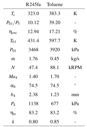
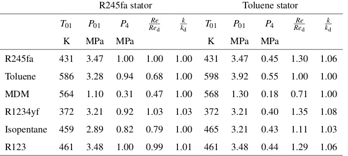
[image:4.612.339.512.425.678.2]are set to 70% and 80% respectively. The resulting thermo-dynamic cycles are described in Tab. 1. The Toluene cycle is suitable for heat-source temperatures in excess of 600 K, whilst the R245fa cycle is suitable for heat-source tempera-tures around 450 K.
Table 1. Thermodynamic cycles and turbine designs
R245fa Toluene
Tc 323.0 383.3 K
P01/P5 10.12 39.20
-ηorc 12.94 17.21 %
T01 431.4 597.7 K
P01 3468 3920 kPa
˙
m 1.76 0.45 kg/s
N 47.4 88.1 kRPM
Ma4 1.40 1.70
-α4 74.5 74.5 ◦
b4 2.38 1.23 mm
P4 1138 677 kPa
ηts 83.2 83.2 %
k 0.80 0.85
val-Table 2. Turbomachinery design inputs
Ns νts ψ φ r5/r4 r4 ζn
0.55 0.68 0.90 0.25 0.55 40 mm 0.11
ues defined in the literature [37, 38]. Since the focus of this study is to investigate working-fluid replacement effects, rather than designing a turbine for a specific ORC applica-tion, the rotor inlet radius is set arbitrarily to 40 mm, and the mass-flow rate and power output are outputs from the turbine design process. The resulting turbine designs are also given in Tab. 1. The polytropic indexkis calculated according to in Ref. [23]
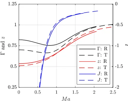
The extent to which non-ideal gas dynamics are ex-pected within the turbine is investigated in Fig. 1 by de-termining how the compressibility factorz, the fundamental derivative Γ, and the parameterJvary during an expansion fromT01andP01to increasing values of Mach number,Ma.
The compressibility factor is defined as:
z= P
ρRT , (2)
wherePis the pressure,ρis the density,Ris the specific-gas constant andTis the temperature. The compressibility factor is a measure of how non-ideal a gas behaves at a specific operating point, with z=1 corresponding to an ideal state. The fundamental derivative is defined as:
Γ=1+ρ
a
∂a
∂ρ
s
, (3)
whereais the local speed of sound andsis the entropy. Fi-nally,Jis defined as:
J=1−Γ− 1
Ma2. (4)
For a dense gas,Γ<1, which corresponds to a reduction in the speed of sound through an expansion [8], whilst non-classical fluid dynamic effects are predicted whenJ>0 [39]. From Fig. 1 it is observed thatΓ<1 butJ<0 during expan-sion up toMa=2.5. Therefore, for the expansion of Toluene or R245fa within a typical ORC turbine, conventional fluid dynamic effects are expected (i.e., compression shocks and expansion fans). However, the fluid behaviour is still non-ideal with 0.5<z<1 for both working fluids.
3 Supersonic stator design
A 2D minimum-length nozzle design model is used to design the supersonic part of an ORC turbine stator. This model is based on the method of characteristics (MoC) and is coupled to a real gas equation of state [40] to account for non-ideal
Fig. 1. Γ, z and J for expansion of R245fa and Toluene from 0.95Pcrand1.01Tcrto increasing Mach numbers
fluid behaviour. The MoC model has been previously vali-dated using CFD for the design of two converging-diverging nozzles operating with R245fa and Toluene with the same inlet conditions and Mach numbers as those given in Tab. 1 [41]. It was observed that the MoC model produces su-personic nozzles that expand the working fluids to the de-sired Mach number. However, weak oblique shocks were observed within the nozzle, which are attributed to the flow interaction with the nozzle wall boundary layers which re-duce the effective nozzle flow area. The nozzle design could be improved by widening the nozzle passage to account for this boundary layer displacement, but since the outlet Mach numbers agree to within 1%, this further complication was deemed unnecessary.
Using the validated supersonic nozzle designs, the su-personic stators can be constructed. The purpose of this pa-per is not to complete a full optimisation of the stator design, but to investigate the effects of working-fluid replacement in ORC supersonic stators. Therefore, instead of implementing a sophisticated design optimisation model, similar to those reported in the Refs. [19,21], a stator design method has been developed that facilitates the quick generation of a stator ge-ometry that is suitable for this investigation. A summary of the design method and the final stator designs is given in 7.
4 CFD simulation formulation and design validation
[image:5.612.319.535.38.208.2]The inlet conditions were set to the turbine total inlet condi-tions. The radius of the CFD outlet domain was set to 38 mm rather than setting it to the rotor inlet radius (r4= 40 mm) to
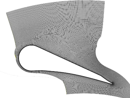
[image:6.612.310.542.240.440.2]ensure the outlet domain is sufficiently downstream of the trailing-edge wake such that the wake is fully mixed out be-fore it reaches the boundary. The outlet boundary conditions were set to the average static pressure, with the pressure pro-file blend set to 5%. The outlet pressures were estimated by applying a 1D mass, energy and momentum balance be-tween the rotor inlet radius and the radius of the CFD outlet domain. This corresponded to outlet pressures of 1000 kPa and 550 kPa for the R245fa and Toluene nozzles respectively. The k-ω SST turbulence model with automatic wall func-tion was selected, and the high-resolufunc-tion scheme was used for both the advection and turbulence calculations. To ac-count for non-ideal fluid properties, REFPROP was used to generate fluid property look-up tables which are accessed by CFX during the simulations. During previous studies it has been found that a table size of 100×100 is sufficient, with the change in the nozzle loss coefficient predicted by this ta-ble size compared to a tata-ble size of 250×250, being less than 0.1% [41]. The grid-independent meshes used for the R245fa and Toluene stators were both constructed from 1.4×10⁵ el-ements; an example of the mesh is shown in Fig. 2.
Fig. 2. Stator mesh consisting of1.4×105elements
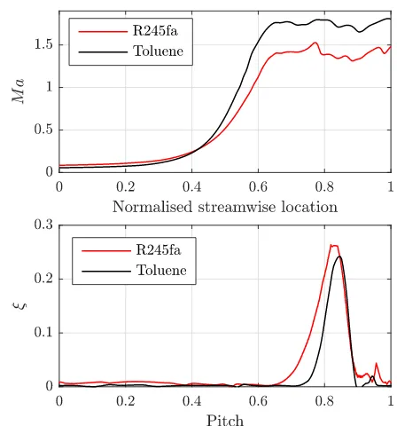
The Mach number contours predicted by the CFD simu-lations for the two stators are shown in Figs. 3 and 4, whilst the Mach number distributions along the nozzle centreline are shown in the top plot in Fig. 5. It is apparent that the flow is expanded within the diverging part of the supersonic nozzle to the desired Mach number for both stator designs. Downstream of the diverging section a more complex flow pattern is observed for both stators. This is the consequence of the generation of shockwaves at the trailing edge, and the interaction of these shocks with the boundary layer that de-velops on the stator blade walls. This shockwave-boundary layer interaction leads to an uneven distribution in the cen-treline Mach number downstream of the stator trailing edge,
as observed in Fig. 5 for normalised streamwise locations greater than 0.7. This figure also displays the local loss co-efficient at the rotor inlet radius, which is defined as:
ξ= h−hs
h01−h4s
, (5)
where h andhs are the local enthalpy and local isentropic
enthalpy respectively, h01 is the total inlet enthalpy andh4s
is the mass-averaged isentropic enthalpy across the whole rotor inlet. The greatest source of loss for both nozzles is in the wake generated downstream of the stator trailing edge, whilst a second source of loss is associated with the trailing-edge shocks observed at a normalised pitch of 0.95.
Fig. 3. Contours of absolute Mach number predicted by CFD for the R245fa supersonic stator vane
The overall performance of both stators is evaluated by calculating the overall stator loss coefficient ζn, which is
based on the mass-averaged static outlet conditions at the ro-tor inlet radius:
ζn=
h4−h4s 1 2c24
. (6)
The loss coefficients are 0.0672 and 0.0449 for the R245fa and Toluene stators respectively, which are both lower than the value specified for the preliminary design (Tab. 2). Since the R245fa stator expands to a lower Mach number than the Toluene stators, this implies the larger loss is the result of a wider and deeper wake, rather than being as-sociated with increased shock losses. This can be observed in Figs. 3 and 4, and is further confirmed by comparing the loss profiles in Fig. 5. It is worth noting that ζn has been
[image:6.612.59.283.360.528.2]Fig. 4. Contours of absolute Mach number predicted by CFD for the Toluene supersonic stator vane
Fig. 5. CFD results for the R245fa and Toluene supersonic stators: stator centreline Mach number (top); local loss coefficient at rotor inlet radius (r4= 40 mm) (bottom).
downstream, at a radius of 39 mm. At this location, the flow is more mixed-out, but it was found that the change in the loss coefficients was negligible.
Based on the area-averaged velocity components ob-tained from the CFD simulations, and the rotational speeds defined in Tab. 1, the velocity triangles at the rotor inlet can be constructed (Fig. 6). The absolute flow angles α4
[image:7.612.321.540.43.276.2]predicted by CFD for the R245fa and Toluene stators are 75.4◦and 76.0◦respectively, which are higher than the de-sign value of 74.5◦. The causes a shift in the velocity trian-gle, and a reduction in the relative flow angle. The mass-flow rates predicted from the CFD simulations are 1.74 kg/s and
Fig. 6. Comparison of the design point rotor inlet velocity triangles with the area-averaged rotor inlet velocity triangles obtained from the CFD simulations for the R245fa (top) and Toluene (bottom) stators
0.44 kg/s for the R245fa and Toluene stators respectively. These are slightly less than the design values and correspond to percentage reductions of 1.2% and 3.3%. This reduction may be due to boundary-layer blockage effects, which re-duce the effective throat width, thereby reducing the mass-flow rate that can pass through the stator. Referring to Tab. 4, the design point throat Reynolds numbers for the R245fa and Toluene stators are 2.52×10⁶ and 1.09×10⁶
respec-tively. Therefore, these results are consistent with boundary layer theory, which would predict a reducing boundary layer displacement thickness with increasing Reynolds number.
Overall, the stator designs achieve conditions that are close to the desired flow conditions at the rotor inlet. Further refinement and optimisation could improve the stator perfor-mance further, which may include adapting the MoC model to account for boundary layer blockage, increasing the num-ber of stator vanes to reduce the loss coefficient [23], or using advanced optimisation methods to improve the stator blade profile [19, 21]. However, this was not one of the objec-tives of this study. It should also be noted that since these were quasi-2D simulations, no consideration has been given to end-wall effects, and particularly the end-wall boundary layers which would further reduce the mass-flow rate and stator loss coefficient. Further studies should take these ef-fects into account.
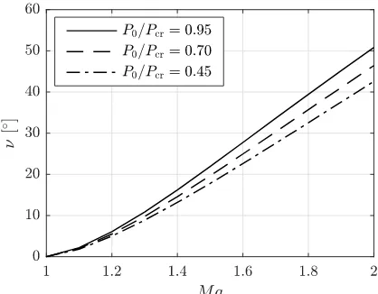
5 Scaling of the stator design point
[image:7.612.60.284.281.521.2]nozzle, it was suggested that by conserving the amount of flow turning within the nozzle (i.e., the Prandtl-Meyer func-tion,ν), the nozzle design point could be scaled to alterna-tive working fluids. To expand on this idea,νis plotted in Fig. 7 for the expansion of R245fa from 0.95Pcr, 0.70Pcrand
0.45Pcrto a range of different Mach numbers. As observed,
expansion from a lower pressure results in reduced flow turn-ing for expansion to the same Mach number. Therefore, it is suggested that by assuming thatνremains constant, the out-let Mach number following a change in working fluid or inout-let conditions can be predicted through interpolation of the data in Fig. 7. However, in the previous study [41] this method was only accurate when there was no significant change in the polytropic indexk. More specifically, predictions made by conservingνagreed with the CFD results to within 2%, provided that 0.9<k/kd<1.1, wherekd is polytropic
in-dex associated with the original design point. This suggests that using the same stator with different working fluids will only be possible if the two fluids undergo a similar change in density (i.e.,ρ/ρ0) during an isentropic expansion across a
defined pressure ratio (P/P0). Furthermore, considering that
νcan be approximated by an expression that is a function of
Maandk[23], it follows that if a working fluid and the total inlet conditions could be appropriately selected to conserve νandk, the performance of the nozzle and the nozzle outlet Mach number would be the same.
Fig. 7. Variation inνfor the expansion of R245fa from different total inlet pressures to a range of Mach numbersMa
The relationship betweenkand the total inlet conditions is explored in Fig. 8, for a number of common organic work-ing fluids. For each workwork-ing fluid an isentrope is constructed that starts at 0.95Pcand 1.01Tc. For different total inlet
pres-sures along this isentrope the outlet Mach number and cor-responding static outlet pressure are selected to ensure the same value forνthat is associated with either the R245fa or Toluene stator design. The ratios P/P0 andρ/ρ0 are then
determined for an array of pressures ranging from the inlet pressure to the outlet pressure, and kis determined using a linear regression. The results shown in Fig. 8 are normalised
[image:8.612.65.274.378.541.2]by the design point polytropic indexkd.
Fig. 8. The variation in the normalised polytropic indexk/kdfor the
expansion of different working fluids from different reduced total in-let pressuresP0/Pcr. For each case the static outlet conditions are
selected to maintain the same Prandtl-Meyer functionνthat is as-sociated with the original design point: R245fa stator (top); Toluene stator (bottom).
The results from Fig. 8 can be used as a basis for scal-ing the two stator design points to alternative workscal-ing flu-ids. For the six working fluids considered, the total inlet conditions and static outlet pressure at the CFD outlet ra-dius (38 mm) are selected to ensure thatνis conserved, and that the ratiok/kd≈1. The resulting scaled design points
for the two stators are given in Tab. 3. During this scaling, the expansion process is assumed to be isentropic and there-fore there is no consideration of any shock or viscous losses within the stator; hence, the scaling process is an oversimpli-fication as these effects will undoubtably be present within ORC turbines. However, providing that the stator nozzle is performing at the design point any shockwaves present will at the stator trailing edge. Moreover, viscous losses are con-fined to the stator blade wall, causing an effective reduction in the passage area, but not an increase the freestream en-tropy. Therefore, the isentropic assumption should be valid for the flow conditions within the stator passage. However, if this is found to be an oversimplication, this assumption will be refined in future studies.
The deviation in the Reynolds number ranges between 0.47Redand 1.03Redfor the R245fa stator, and 0.71Redand
1.35Redfor the Toluene stator. These deviations are within
the acceptable range previously determined (0.5<Re/Red<
Table 3. Stator inlet conditions and static outlet pressures for the alternative working fluid studies on the R245fa and Toluene stators
R245fa stator Toluene stator
T01 P01 P4 ReRed kkd T01 P01 P4 ReRed kkd
K MPa MPa K MPa MPa
R245fa 431 3.47 1.00 1.00 1.00 431 3.47 0.45 1.30 1.06
Toluene 586 3.28 0.94 0.68 1.00 598 3.92 0.55 1.00 1.00
MDM 564 1.10 0.31 0.47 1.00 568 1.30 0.18 0.71 1.00
R1234yf 372 3.21 0.92 1.03 1.03 372 3.21 0.40 1.35 1.08
Isopentane 459 2.89 0.82 0.79 1.00 465 3.21 0.43 1.11 1.03
R123 461 3.48 1.00 0.99 1.01 461 3.48 0.44 1.29 1.06
it is possible to select a suitable total inlet condition that con-serveskfor all working fluids except R1234yf, as is evident from Fig. 8. However, for the Toluene nozzle this is only possible for MDM. Therefore, for R245fa, R1234yf, Isopen-tane and R123, the total conditions are set to 0.95Pcr and
1.01Tcr, and this corresponds to maximum deviations in k
that are between 3% and 6%.
For each working fluid, two CFD simulations are per-formed to assess the performance of the R245fa and Toluene stators with that working fluid. Then, for each combination of stator and working fluid, the midline Mach number distri-bution, the loss profile at the rotor inlet radius, and the over-all stator loss coefficient were obtained. The Mach number distributions and loss profiles are shown in Figs. 9 and 10 respectively. From these figures, it is clear that for the cases given in Tab. 3 the performance of both stators remains the same. This indicates that the method employed has success-fully scaled the stator design point to the alternative fluids.
The values forζncalculated from the CFD simulations
range between 0.0672 and 0.0582 for the R245fa stator, op-erating with R245fa and MDM respectively, and range be-tween 0.0471 and 0.0449 for the Toluene stator, when operat-ing with R245fa and Toluene respectively. Similarly, for the R245fa stator,α4ranges between 75.3◦and 75.4◦for MDM
and Toluene, whilst for the Toluene statorα4ranges between
75.7◦and 76.0◦for R123 and Toluene. The mass-flow rates range between 0.58 kg/s and 1.82 kg/s for the R245fa stator, and 0.22 kg/s and 0.58 kg/s for the Toluene stator.
Overall, the CFD results obtained for the two stators operating with alternative fluids have shown that the per-formance of the stator remains the same, provided that the change inkis not significant. Under this condition the stator performance can be predicted by conservingν.
6 Implementation within practical ORC systems
To conclude this paper it is necessary to consider the practi-cal ORC systems in which working-fluid replacement could be used for beneficial effect. Similitude theory hypothe-sises that the non-dimensional performance of a turbine is the same when the Mach number velocity triangles at the
ro-Fig. 9. Midline Mach number distributions for the two stators oper-ating with alternative working fluids: R245fa (top); Toluene (bottom).
tor inlet and outlet are the same. Therefore, considering the similarities in the Mach numbers and absolute flow angles at the rotor inlet predicted by the CFD simulations, the rotor blade velocityu4can be selected to ensure the same relative
flow angle, and relative Mach number at the rotor inlet; note that the subscripts ‘4’ and ‘5’ refer to the rotor inlet and rotor outlet respectively, following on from the convention where ‘1’, ‘2’ and ‘3’ refer to the turbine inlet, stator leading edge and stator trailing edge respectively.
Onceu4is known, a suitable method for predicting the
[image:9.612.317.537.244.480.2]Fig. 10. Local loss coefficient atr4for the two stators operating with
alternative working fluids: R245fa (top); Toluene (bottom).
therefore the complexity of requiring similar scaling meth-ods based on the Prandtl-Meyer number is removed. More-over, the flow conditions within the rotor are further away from the critical point, and therefore non-ideal gas effects will be less prevalent. Based on this assumption,u4can be
related to the isentropic static enthalpy at the rotor outleth5s
by assuming the rotor operates at the design point isentropic velocity ratioνts, hence:
h5s=h01−
1 2c
2
s =h01−
1 2
u4
νts
2
. (7)
This allows the turbine static outlet pressureP5to be
deter-mined, from which the total-to-static pressure ratio (P01/P5)
is also known. Finally, assuming that the rotor operates at the design isentropic velocity ratio implies the same total-to-static isentropic efficiency ηts, which allows the turbine
power to be estimated:
˙
Wt=m˙ηts(h01−h5s). (8)
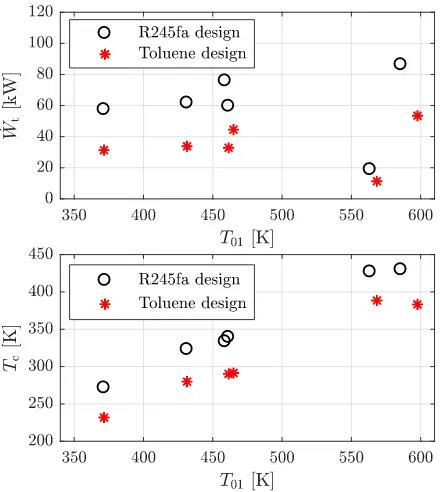
The results from this analysis are shown in the top plot of Fig. 11, and these suggest that operating the R245fa tur-bine with alternative working fluids could allow the same turbine to be used within different ORC systems with T01
ranging between 372 K and 586 K, and ˙Wtranging between
18.9 kW and 86.3 kW. Similarly, operating the Toluene tur-bine with alternative fluids could facilitate the use of the same turbine within ORC systems withT01ranging between
372 K and 598 K, and ˙Wt ranging between 11.4 kW and
[image:10.612.65.286.39.281.2]53.5 kW.
Fig. 11. Turbine power (top) and ORC condensation temperatures (bottom) for the R245fa and Toluene turbines when operating with alternative working fluids at different turbine inlet temperatures
At first glance these results suggest the feasibility of using the turbine within multiple ORC systems, thus facil-itating economy-of-scale improvements. However, it is also necessary to consider the resulting ORC condensation tem-peraturesTc, which can be obtained from P5 and are given
in the bottom plot in Fig. 11. When evaluating these re-sults it becomes apparent that not all of the ORC systems will be practical. For example, the Toluene turbine couldn’t be used with R1234yf, R245fa, R123 and Isopentane be-cause these working fluids result in condensation tempera-tures below 300 K, which could not be achieved without a very low-temperature heat sink. In comparison, the R245fa turbine could be used with all the fluids with the exception of R1234yf, sinceTcfor these cases are all above 300 K. From
the plot in the bottom half of Fig. 11 it is also apparent that a relationship between increasingT01and increasingTcexists.
This echoes the relationship between the critical temperature and the normal boiling point that has been shown within the literature [43]. Therefore, given that the critical tempera-ture of Toluene is greater than R1234yf, R245fa, R123 and Isopentane, whilst R245fa has the second lowest critical tem-perature after R1234yf, this suggests that a supersonic tur-bine design cannot be scaled to a working fluid with a lower critical temperature, as this will result in a low condensation temperature and an infeasible ORC system.
fluid, T01, P01 andP4were determined to conserve both k
and ν within the stator. The flow angles α4 and β4 were
assumed constant andP5was determined from Equation 7.
The mass-flow rate is determined from the reduced flow co-efficient ˙m/(ρ∗a∗), which is assumed constant since the sta-tor geometry does not change. This, in turn, determines ˙Wt
if it is assumed thatηts is constant; such an assumption can
[image:11.612.64.287.193.366.2]be made since similitude theory hypothesises that the turbine performance will be the same if the rotor velocity triangles and flow coefficient are maintained. The results from this analysis are shown in Fig. 12.
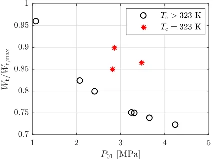
Fig. 12. Power produced from the R245fa turbine when the design point is scaled to alternative working fluids
In Fig. 12, ˙Wt has been normalised by the maximum
power ˙Wt,max. This is done because within the scaling
pro-cess the designer has no control overP5, and therefore a high
condensation temperature could result which would have a detrimental effect on the ORC performance. The maximum power is calculated by assuming that the working fluid is ex-panded from the same total inlet conditions to the minimum permissible condensation temperature. The minimum con-densation temperature depends on the availability and tem-perature of the heat sink, and the size of the ORC condenser, which affect the minimum temperature difference within the condenser. For this analysis, a value of 323 K is assumed to be a reasonable value. For working fluids that have a sub-atmospheric condensation pressure at 323 K, the minimum condensation temperature is increased to the saturation tem-perature at 100 kPa to avoid sub-atmospheric condensation. The mass-flow rate for the maximum power case is deter-mined by assuming that the same amount of thermal energy is available to the ORC system in both cases.
From Fig. 12, it is observed that ˙Wt ranges between
17.8 kW for MDM and 112 kW for Benzene. Furthermore, the results have been plotted in order of increasing criti-cal temperature, and therefore correspond to ORC systems that are suitable for different heat-source temperatures. This highlights the possibility of using the same turbine within different ORC systems by matching the working fluid to the
available heat source. MDM and Benzene also correspond to the maximum and minimum values for the normalised power, with values of 0.96 and 0.72 respectively, suggesting there could be up to a 30% reduction in the normalised power output following working-fluid replacement, compared to a system with an optimised condensation pressure.
A relationship between P01 and the normalised power
is also observed (Fig. 13), with lower inlet pressures corre-sponding to higher normalised powers. This trend is even clearer when the working fluids are divided by how the op-timised condensation temperature is determined (i.e.,Tc=
323 K, or defined by the saturation temperature at 100 kPa). A correlation is also observed between a higher normalised power and a condensation temperature that is closer to the minimum permissible condensation temperature. For exam-ple, for the MDM system, which has the highest normalised power, the condensation temperature is 431.5 K, whilst the condensation temperature at 1 bar is 425.2 K. For the Ben-zene system, which has the lowest normalised power, the condensation temperature is 411.1 K, compared to a conden-sation temperature at 1 bar of 352.8 K. The corresponding condensation pressures for these two working fluids are 117 and 425 kPa respectively. In other words, using the R245fa turbine with Benzene would lead to an under expansion of the working fluid, compared to an optimal cycle in which the fluid is expanded down to 100 kPa. The cycle efficien-cies for the scaled cycles range between 8.1% (MDM) and 15.7% (cyclopentane), compared to 8.5% and 21.3% for the same working fluids, but with expansion down to the mini-mum permissible condensation temperature.
Fig. 13. Relationship between the normalised power produced from the R245fa turbine when operating with different working fluids and the turbine inlet pressureP01. The results are split into two groups:
(i)Tc=323 K, and (ii) saturation temperature at 100 kPa (i.e., Tc>
323 K).
[image:11.612.321.534.428.587.2]on the reduced head coefficient∆hs/a∗
2
, reduced flow coef-ficient ˙m/ρ∗a∗and reduced rotational speedN/a∗. From the CFD results presented in Section 5, it was found that the re-duced flow coefficients equalled 1.12×10⁻⁴and 3.59×10⁻⁵ for the R245fa and Toluene stators. This was to be expected since the stator geometry does not change. However, by conserving both νandkwhen changing the working fluid we have conserved the Mach number triangles which means that the reduced head coefficient and the reduced rotational speeds also remain the same. For the results for the R245fa turbine shown in Fig. 12, the reduced head coefficients range between 3.10 and 3.13, which corresponds to a deviation of less than 1%. This small deviation arises because it was not always possible to select an operating point that conservedk
(i.e., Fig. 8). Nonetheless, these results suggest that the mod-ified similitude theory is suitable for supersonic turbines, so long askandνdo not deviate significantly.
The scaled rotor rotational speed ranges between 44 and 71 kRPM, which correspond to operating with R123 and cy-clopentane respectively. This speed range is well within the practical limits for a rotor diameter of 80 mm. Therefore, the main practical constraint on using the same turbine with multiple working fluids is the variation in shaft power, which could require a different generator. However, even if a differ-ent generator is required, it is still envisioned that the same turbine assembly can be used, thereby removing the need to develop a new bespoke turbine design.
In summary, this section has demonstrated how a super-sonic turbine design can be scaled to an alternative work-ing fluid. However, the scalwork-ing process is subject to con-straints which are imposed by the properties of the original and replacement working fluids, namely 0.9<k/kd<1.1
andTcr>Tcr,d, which narrows the potential operational
enve-lope of a particular turbine design. Nonetheless, the results suggest that through the careful selection of a replacement working fluid, the same ORC turbine could be suitable for different applications. However, this is not a one size fits all approach, as the effect of working-fluid replacement on the condensation pressure, and the possible reduction in the power output compared to an optimised thermodynamic cy-cle needs to be considered. In this instance, there is a trade-off between minimising the development and manufacturing costs of the turbine by using an existing design, but accepting a slight reduction in performance, and developing a bespoke design with optimal performance, but with higher associated costs. To answer this question a thorough economic assess-ment of the two options should be conducted.
Before concluding, a number of issues which require further investigation should be discussed. Firstly, it is reiter-ated that the stator designs have been obtained using a sim-ple geometrical construction, and as such have not been opti-mised using advanced design techniques which are becoming more routinely used. Thus, further verification is required for an optimised stator design. Furthermore, the results have been obtained using simple assumptions pertaining to the ro-tor design. Therefore, further research efforts must also fo-cus on a more detailed 3D rotor design phase, complemented with 3D CFD simulations of the complete stator and rotor
assembly. With this in place, the effects of working-fluid re-placement in supersonic ORC turbines can be studied in fur-ther detail. Finally, following from Refs. [24, 42], unsteady CFD simulations will also be necessary to investigate the role of unsteady effects on working-fluid replacement.
7 Conclusions
The effect of working-fluid replacement as a means of widening the operating envelope of a particular ORC super-sonic turbine has been studied in this paper. Supersuper-sonic sta-tors have been designed for R245fa and Toluene, and their design point performance verified using quasi-2D CFD sim-ulations completed using ANSYS CFX. The design point for each stator was then scaled to alternative working fluids by conserving the Prandtl-Meyer function and the polytropic in-dex. The CFD results show that provided the Prandtl-Meyer function and the polytropic index can be conserved, the cen-treline Mach number distribution and rotor inlet loss profile remain the same. Furthermore, the stator loss coefficients for the R245fa stator ranged between 0.0672 and 0.0582, whilst for the Toluene stator they ranged between 0.0471 and 0.449. The rotor inlet flow angles changed by less than 0.3◦for both stators, further confirming that the design point has been ac-curately scaled to alternative working fluids.
Studies concerning the ORC system show that working-fluid replacement could facilitate using the same turbine in different applications. For example, the R245fa design could be used within ORC systems with maximum tempera-tures ranging between 431 K (R245fa) and 585 K (Toluene), whilst the power output could range between 17 kW (MDM) and 112 kW (Benzene). This suggests the potential to match the working fluid to the heat-source temperature and thermal content, whilst using the same turbine design. However, it is observed that working-fluid replacement may only be pos-sible if the replacement working fluid has a higher critical temperature than the design working fluid. Furthermore, de-pending on the working fluid there could be up to a 30% re-duction in the power output compared to an ORC system that is designed specifically for the new heat source. Nonetheless, from the point of view of turbine economy-of-scale improve-ments, working-fluid replacement could be used to beneficial effect. Future work should study the effects of working-fluid replacement on the full 3D flow within ORC supersonic tur-bines, and validate these ideas experimentally.
Acknowledgements
This work was supported by the UK Engineering and Physical Sciences Research Council (EPSRC) [grant num-bers: EP/P004709/1 and EP/P009131/1].
References
[1] Markides, C. N., 2013. “The role of pumped and
[2] Markides, C. N., 2015. “Low-concentration solar-power systems based on organic Rankine cycles for distributed-scale applications: Overview and further developments”. Frontiers in Energy Research, 3 (De-cember), pp. 1–16.
[3] Qiu, G., Shao, Y., Li, J., Liu, H., and Riffat, S. B., 2012. “Experimental investigation of a biomass-fired ORC-based micro-CHP for domestic applications”.Fuel,96, pp. 374–382.
[4] Freeman, J., Hellgardt, K., and Markides, C. N., 2015. “An assessment of solar-powered organic Rankine cy-cle systems for combined heating and power in UK do-mestic applications”.Appl Energ,138, pp. 605–620. [5] Freeman, J., Hellgardt, K., and Markides, C. N., 2017.
“Working fluid selection and electrical performance op-timisation of a domestic solar-ORC combined heat and power system for year-round operating in the UK”.
Appl Energ,186, pp. 291–303.
[6] Lang, W., Colonna, P., and Almbauer, R., 2013. “As-sessment of waste heat recovery from a heavy-duty truck engine by means of an ORC turbogenerator”. J Eng Gas Turb Power,135(4).
[7] Colonna, P., Casati, E., Trapp, C., Mathijssen, T., Lar-jola, J., Turunen-Saaresti, T., and Uusitalo, A., 2015. “Organic Rankine cycle power systems: From the con-cept to current technology, applications, and an outlook to the future”. J Eng Gas Turb Power,137(10). [8] Thompson, P. A., 1971. “A fundamental derivative in
gas dynamics”.Phys Fluids,14(9), pp. 1843–1849. [9] Colonna, P., and Guardone, A., 2006. “Molecular
inter-pretation of nonclassical gas dynamics of dense vapors under the van der Waals model”.Phys Fluids,18(5). [10] Kluwick, A., 2017. “Non-ideal compressible fluid
dy-namics: A challenge for theory”.J Phys Conf Ser,821. [11] Mathijssen, T., Gallo, M., Casati, E., Nannan, N. R., Zamfirescu, C., Guardone, A., and Colonna, P., 2015. “The flexible asymmetric shock tube (FAST): A Lud-wieg tube facility for wave propagation measurements in high-temperature vapours of organic fluids”. Exper-iments in Fluids,56(195).
[12] Gori, V., Vimercati, D., and Guardone, A., 2017. “Non-ideal compressible-fluid effects in oblique shock waves”.J Phys Conf Ser,821.
[13] Alferez, N., and Touber, E., 2017. “Shock-induced en-ergy transfers in dense gases”.J Phys Conf Ser,821. [14] Aldo, A. C., and Argrow, B. M., 1995. “Supersonic
minimum length nozzle design for dense gases”. J Fluid Eng,115(2), pp. 270–276.
[15] Hoffren, J., Talonpoika, T., Larjola, J., and Siikonen, T., 2002. “Numerical simulation of real-gas flow in a supersonic turbine nozzle ring”.J Eng Gas Turb Power,
124(4), pp. 395–403.
[16] Colonna, P., Rebay, S., Harinck, J., and Guardone, A., 2006. “Real-gas effects in ORC turbine flow simu-lations: Influence of thermodynamic models on flow fields and performance parameters”. In European Con-ference on Computational Fluid Dynamics.
[17] Harinck, J., Turunen-Saaresti, T., Colonna, P., Rebay,
S., and van Buijtenen, J., 2010. “Computational study of a high-expansion ratio radial organic Rankine cycle turbine stator”.J Eng Gas Turb Power,132(5). [18] Harinck, J., Pasquale, D., Pecnik, R., Buijtenen, J. V.,
and Colonna, P., 2013. “Performance improvement of a radial organic Rankine cycle turbine by means of auto-mated computational fluid dynamic design”. P I Mech Eng A-J Pow,227(6), pp. 637–645.
[19] Pasquale, D., Ghidoni, A., and Rebay, S., 2013. “Shape optimization of an organic Rankine cycle radial turbine nozzle”. J Eng Gas Turb Power,135(4).
[20] Persico, G., 2017. “Evolutionary optimization of cen-trifugal nozzles for organic vapours”. J Phys Conf Ser,
821.
[21] Pini, M., Persico, G., Pasquale, D., and Rebay, S., 2015. “Adjoint method for shape optimization in real-gas flow applications”.J Eng Gas Turb Power,137(3). [22] Bufi, E. A., and Cinnella, P., 2017. “Robust optimiza-tion of supersonic ORC nozzle guide vanes”. J Phys Conf Ser,821.
[23] Wheeler, A. P. S., and Ong, J., 2013. “The role of dense gas dynamics on organic Rankine cycle turbine perfor-mance”. J Eng Gas Turb Power,135(10).
[24] Wheeler, A. P. S., and Ong, J., 2014. “A study of the three-dimensional unsteady real-gas flows within a transonic ORC turbine”. In Proceedings of the ASME Turbo Expo 2014, no. GT2014-25475.
[25] Spinelli, A., Pini, M., Dossena, V., Gaetani, P., and Casella, F., 2013. “Design, simulation, and construc-tion of a test rig for organic vapors”. J Eng Gas Turb Power,135(4).
[26] Reinker, F., Hasselmann, K., aus der Wiesche, S., and Kenig, E. Y., 2016. “Thermodynamics and fluid me-chanics of a closed blade cascade wind tunnel for or-ganic vapors”.J Eng Gas Turb Power,138(5).
[27] Dur´a Galiana, F. J., Wheeler, A. P., and Ong, J., 2016. “A study of trailing-edge losses in organic Rankine cy-cle turbines”.J Turbomach,138(12).
[28] Head, A. J., Servi, C. D., Casati, E., Pini, M., and Colonna, P., 2016. “Preliminary design of the OR-CHID: A facility for studying non-ideal compressible fluid dynamics and testing ORC expanders”. In Pro-ceedings of ASME Turbo Expo 2016, no. GT2016-56103.
[29] Spinelli, A., Cozzi, F., Dossena, V., Gaetani, P., Zocca, M., and Guardone, A., 2016. “Experimental investi-gation of a non-ideal expansion flow of siloxane vapor MDM”. In Proceedings of ASME Turbo Expo 2016, no. GT2016-57357.
[30] Macchi, E., and Astolfi, M., 2017. Organic Rankine Cycle (ORC) Power Systems. Woodhead Publishing. [31] White, M., and Sayma, A. I., 2016. “Investigating
the effect of changing the working fluid on the three-dimensional flow within organic Rankine cycle tur-bines”. In Proceedings of ASME Turbo Expo 2016, no. GT2016-56106.
cycle using similarity concept”.J Eng Gas Turb Power,
138(6).
[33] Invernizzi, C. M., Iora, P., Preßinger, M., and Man-zolini, G., 2016. “HFOs as substitute for R-134a as working fluids in ORC power plants: A thermodynamic assessment and thermal stability analysis”.Appl Therm Eng,103, pp. 790–797.
[34] Zhang, L., Zhuge, W., Zhang, Y., and Chen, T., 2017. “Similarity theory based radial turbine performance and loss mechanism comparison between R245fa and air for heavy-duty diesel engine organic Rankine cy-cles”.Entropy,19(1).
[35] White, M., and Sayma, A. I., 2015. “System and com-ponent modelling and optimisation for an efficient 10 kwe low-temperature organic rankine cycle utilising a radial inflow expander”.P I Mech Eng A-J Pow,229(7), pp. 795–809.
[36] Costall, A. W., Gonzalex-Hernandez, A., Newton, P. J., and Martinez-Botas, R. F., 2015. “Design methodology for radial turbo expanders in mobile organic rankine cy-cle applications”.Appl Energ,157, pp. 729–743. [37] Moustapha, H., Zelesky, M. F., Baines, N. C., and
Japiske, D., 2003. Axial and Radial Turbines. Con-cepts ETI, Inc.
[38] Dixon, S. L., and Hall, C. A., 2013. Fluid Mechan-ics and ThermodynamMechan-ics of Turbomachinery, 7th ed. Butterworth-Heinemann.
[39] Cramer, M. S., and Crickenberger, A. B., 1991. “Prandtl-Meyer function for dense gases”. AIAA Jour-nal,30(2), pp. 561–564.
[40] Lemmon, E. W., Huber, M. L., and McLinden, M. O., 2013. NIST standard reference database 23: Ref-erence fluid thermodynamic and transport properties-REFPROP.
[41] White, M., Sayma, A. I., and Markides, C. N., 2017. “Supersonic flow of non-ideal fluids in nozzles : An application of similitude theory and lessons for ORC turbine design and flexible use considering system per-formance”.J Phys Conf Ser,821.
[42] Rinaldi, E., Pecnik, R., and Colonna, P., 2015. “Un-steady RANS simulation of the off-design operation of a high expansion ratio ORC turbine”. In 3rd Interna-tional Seminar on ORC Power Systems, no. 150. [43] Maizza, V., and Maizza, A., 1996. “Working fluids in
non-steady flows for waste energy recovery systems”.
Appl Therm Eng,16(7), pp. 579–590.
[44] White, M., and Sayma, A. I., 2015. “The application of similitude theory for the performance prediction of radial turbines within small-scale low-temperature or-ganic Rankine cycles”.J Eng Gas Turb Power,137(12).
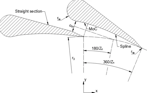
Appendix A: Supersonic stator design
The geometry of the supersonic stator is defined in Fig. 14. The throat widthothis obtained from:
oth=
˙
m
ρ∗a∗b4Zn
, (9)
whereb4is rotor inlet blade height,Znis the number of stator
blades, andρ∗anda∗are the static choked throat conditions, calculated by assuming an isentropic expansion fromT01and
P01. The throat Reynolds number is given by:
Red=
ρ∗a∗Dh
µ , (10)
whereµis the viscosity andDhis the hydraulic diameter.
r3
360/Zn
180/Zn
oth
rle
rte
MoC
Spline Straight section
[image:14.612.308.551.185.340.2]x y
Fig. 14. Geometrical desciption of the supersonic turbine
The geometrical parameters for the two stators are sum-marised in Tab. 4. The leading-edge radii are set torle=oth
andrle=1.5othfor the R245fa and Toluene stators
respec-tively. The stator is constructed by creating a construction circle at the stator inlet radius. The end point of the bottom half of the diverging nozzle obtained using the MoC model is positioned on this construction circle at the point (0,r3),
and rotated such that the nozzle centreline intersects the con-struction circle atθ=180/Zn. The leading and trailing edges
are constructed, and are connected by a straight line to cre-ate the subsonic section. The diverging supersonic section is then connected to the trailing edge using a spline.
Table 4. Stator design parameters
Zn oth Red r3 rte rle
- mm - mm mm mm
R245fa 16 2.97 2.52×10⁶ 41 0.05 2.97
[image:14.612.311.545.557.630.2]