Quantum state correction using a measurement-based feedforward mechanism
Ross J. Donaldson ,1,*Luca Mazzarella,2Ugo Zanforlin,1Robert J. Collins,1John Jeffers,2and Gerald S. Buller11SUPA, Institute of Photonics and Quantum Sciences, School of Engineering and Physical Sciences, Heriot-Watt University,
David Brewster Building, Edinburgh EH14 4AS, United Kingdom
2SUPA, Department of Physics, University of Strathclyde, John Anderson Building, 107 Rottenrow, Glasgow G4 0NG, United Kingdom
(Received 26 March 2019; published 26 August 2019)
One of the weaknesses of quantum optical state postselection schemes is the low success probability. Typically there is a trade-off between amplifier properties such as success probability and output state fidelity. However, here we present a state comparison amplifier for optical coherent states, which features an active measurement and feedforward mechanism to correct for errors made during the initial amplification. The simple and relatively low latency mechanism allows us to correct for a binary phase alphabet. We demonstrate a significant simultaneous improvement in the amplifier characteristic parameters: output state fidelity, correct state fraction, and success probability. This demonstrates that nondeterministic quantum amplification can be enhanced significantly by measurement and feedforward.
DOI:10.1103/PhysRevA.100.023840
I. INTRODUCTION
In conventional optical-fiber communications, optical sig-nals contain a large number of photons per bit and can, in principle, be deterministically amplified with a large gain without the signal being compromised significantly by the ad-dition of noise. This allows these conventional optical signals to be transmitted over intercontinental distances. The same deterministic amplification methods used in conventional op-tical communications cannot simply be applied usefully to low-photon-number quantum states, such as those transmitted in quantum key distribution (QKD) [1,2] or quantum digital signatures [3,4], due to the addition of amplifier noise which will render ineffective any measurement of the quantum prop-erties of the state [5].
The study of nondeterministic noiseless amplification, with the goal of overcoming some of the performance limitations of quantum communications in terrestrial fiber-based networks, is an emerging field of interest. Nondeterministic amplifiers work by postselecting the output based on single or multiple measurement heralding conditions to determine the efficacy of the amplification process [6]. If the heralding conditions are met, then the output is accepted and permitted to be used later; if not, then the signal is discarded. A range of approaches exist, including heralded scissor devices [7], qubit amplifiers [8], thermal photon addition [9–11], and parametric down conversion [12]. For applications in quantum communica-tions, nondeterministic amplifiers which have a high-fidelity amplified output are required to maintain a low quantum bit error rate (QBER). Nondeterministic amplifiers which have a high success probability would also enable a higher proportion of quantum states to be amplified. Furthermore, approaches have already been proposed that may lead to benefits in certain QKD protocols [13–15].
*Corresponding author: [email protected]
The state comparison amplifier (SCAMP) is an approach to nondeterministic amplification which amplifies unknown quantum optical coherent states chosen from an N state discrete nonorthogonal phase alphabet [16–18] defined by {exp (2mπi/N)}, where m = 0, ...,N−1. The SCAMP re-lies on low-amplitude coherent states from an attenuated laser source and does not require complex quantum components. The experimental simplicity of the SCAMP allows this ap-proach to have a high success probability, an example of which is a previous experiment by the authors that has shown a success probability as high as 22% [19]. This high success probability means the success rate of SCAMP can also be high, when used in conjunction with high-repetition-rate laser sources.
Previous implementations of the SCAMP used a single attempt to guess the phase encoding of the input-signal co-herent state. While able to achieve a high success proba-bility, this approach discarded potentially useful information about the input state during an incorrect guess amplification process—information that could potentially be fed forward into further amplification attempts to improve the fidelity, correct state fraction, and success probability. Experimental demonstrations of measurement and feedforward mechanisms have already led to improvements for a range of nondetermin-istic quantum technologies. Examples include enabling deter-ministic one-way optical computing [20–23], improving the single-photon probability of heralded single-photon sources without increasing the multiphoton pulse probability [24–30], reducing light intensity in quantum sensing [31], and enabling deterministic quantum teleportation [32–34]. For applications in quantum computing and quantum communications, the latency of the measurement and feedforward mechanism are important considerations, especially if multiple iterations of the mechanism are required [35].
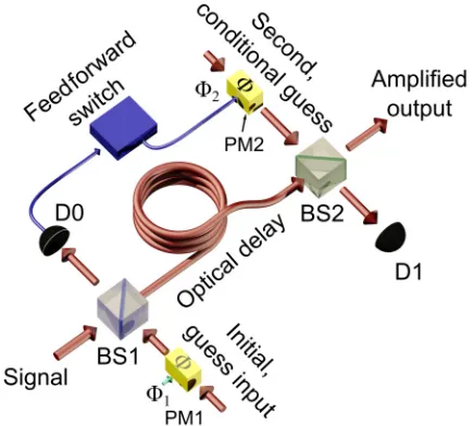
FIG. 1. Schematic diagram of the state comparison amplifier with the measurement feedforward mechanism between two state comparison stages. The amplifier first makes a comparison between an input signal state and locally prepared initial guess state on beam splitter 1 (BS1). One output is monitored by detector D0. This detector sets the phase of the second conditional guess. When triggered, the feedforward switch applies a phase shift of π. Red lines and arrows indicate optical fiber, while blue indicates electrical connections. Phase modulators are denoted PM.
the improvement that the active feedforward mechanism has on the amplified output properties of the SCAMP, we present experimental comparisons of the same SCAMP both with and without an active feedforward mechanism. We also show additional analysis of the system and propose improvements to the experimental procedure for future works.
II. METHODS
A. Description of feedforward SCAMP process
Previous demonstrations of the SCAMP have been per-formed with a single state comparison stage and one- [17] or two- [19] photon subtraction stages to improve the con-ditioning of the amplified output state. Here, the SCAMP ex-perimental setup was composed of two successive state com-parison stages, shown in Fig.1. It has no photon subtraction stages, which would be detrimental to the success probability. The first comparison stage, at beam splitter 1 (BS1), mixes the initial input state and a locally prepared guess state, whose phase is denoted byφ1in Fig.1. This guess state was chosen independently from the choice of signal state, but from the same discrete binary phase alphabet. One of the beam-splitter outputs is detected, using a single-photon detector denoted D0 in Fig. 1. If the guess matches the input signal state, D0 will not fire and the output proceeds to the second state comparison stage, BS2, which in this case operates in a similar manner to the first comparison stage, i.e., φ1=φ2, further amplifying the signal by mixing the signal input to BS2 with a higher-amplitude guess state with the same phase. If, however, the guess at BS1 is chosen incorrectly, an incorrect state is sent to BS2 and a proportion of light is routed to D0 and so it can fire. If D0 does fire, a feedforward switch alters
the phase of the input to the second comparison stage φ2 byπ. This mixes with the incorrect input at BS2 to provide a nearly perfectly amplified output. The choice of two state comparison stages for this binary phase alphabet potentially allows perfect amplification even if there is an incorrect initial guess. Note that in both cases, attenuation introduced by the optical delay can be offset at BS2.
A single-photon detector D1 monitored the output of the second state comparison stage and allowed this stage to be-come part of the postselection conditions for nondeterministic amplification. The decision table for the whole network shows the postselection conditions, i.e., the success criteria when the feedforward mechanism was inactive and active (TableI). As can be seen, the feedforward mechanism enabled more heralding conditions to be accepted in postselection.
The SCAMP operated independently from the signal trans-mitter and so acted in the same manner as a trusted node in a lossy communications channel.
B. Experimental optical system
The optical system was designed around an operational wavelength of 850 nm, chosen as a compromise that achieves a relatively high detection efficiency (≈40%) in the commer-cially available thick-junction silicon single-photon avalanche diode (SPAD) detector, as well as a tolerable loss in the silica fiber (≈2.2 dB/km) [37]. A vertical cavity surface emitting laser diode source was pulsed at a repetition rate of 1 MHz and attenuated to provide optical coherent states,|α, at a low mean photon number per pulse, defined as|α|2 at the signal input to BS1. We chose a low repetition rate of 1 MHz and a pulse width of 1 ns in order to reduce the effect of intersymbol interference and dead-time issues. The experimental system was constructed from single-mode polarization-maintaining fiber components to ensure polarization stability during mea-surements. As shown in AppendixA, the implemented op-tical system was composed of three nested Mach-Zehnder interferometers. The outer interferometer carried a reference coherent state for a final tomography measurement comparing the output of the amplifier with the reference. The two inner interferometers provided pseudo-independent coherent state sources for the initial input state, initial guess input, and second conditional input. The beam-splitting ratios of BS1 and BS2 in this experiment were chosen as t2
1 =0.9:r12 = 0.1 and t2
2 = 0.5:r22 = 0.5, respectively, to give a higher nominal gain than previously demonstrated with SCAMP, where the nominal gain in feedforward SCAMP is defined as g2=(1/r1r2)2, which in the absence of loss gives a value of 20 forr2
1=0.1, andr22=0.5.
The feedforward mechanism was implemented using a simple solid-state relay, triggered by D0. The time for the electrical relay to be activated included the effects of latency of SPAD D0 additional electronic components, and the rise time of the switch, as detailed in AppendixB. The activation time, ≈150 ns, meant that the state comparison stages had to be separated by an optical delay at least as long as this time. This optical delay was provided by 36 meters length of low-loss optical fiber.
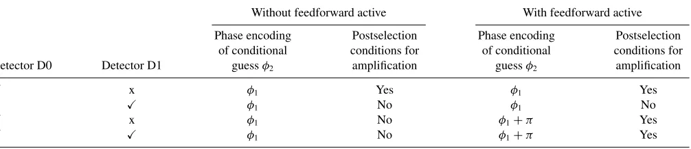
TABLE I. Postselection heralding conditions for the feedforward state comparison amplifier operating with measurement and feedforward active and inactive. When the feedforward mechanism is inactive, there is no correction to the second guess phase encoding (φ2) when the trigger detector records an event. When the feedforward mechanism is active, the second guess is altered by a phase shift ofπ, corresponding to a voltage ofVπ, relative to the initial guess.
Without feedforward active With feedforward active
Detector D0 Detector D1
Phase encoding of conditional
guessφ2
Postselection conditions for amplification
Phase encoding of conditional
guessφ2
Postselection conditions for amplification
x φ1 Yes φ1 Yes
x φ1 No φ1 No
x φ1 No φ1+π Yes
φ1 No φ1+π Yes
model was based on theory described in our previous work [17,19]. Data points are the average of 25 individual 1-second-duration measurements for each|α|2 value. This duration of measurements were chosen to reduce Poisson error in the photon-count data while maintaining interferometric stability. Although the indication of a wrong guess at D0 was highly reliable, the feedforward mechanism could not discriminate between a signal event or a background count. Optical com-ponent losses, nonunity detection efficiency, and the vac-uum state probability of the Poissonian distribution were all sources of errors, and particularly evident at low mean-photon numbers. Uncertainties in data points are calculated from error propagation of the standard deviations of each experimental data point. These values typically lay less than 2% of the actual values, and hence the data-point values cover the error bars.
III. RESULTS AND DISCUSSION
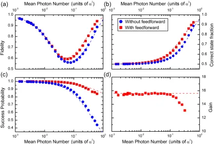
We present results for the four characteristic parameters used to benchmark the performance of the SCAMP: am-plified output state fidelity, correct state fraction, success probability, and effective gain (see AppendixE for details). The amplified output state fidelity gives an indication of how well a reference state and the postselected amplified output overlap. The correct state fraction is the fraction of correctly postselected states which are known to have had a correct initial or corrected secondary guess. The effective gain is the increase in intensity of the input arbitrary quantum coherent state after it has been amplified. These quantities are derived from the measurements at the outputs of the outer tomography interferometer. The success probability is the probability that a randomly chosen quantum coherent state within the alpha-bet will meet the amplification postselection conditions. The success rate of the amplifier is simply the success probability multiplied by the clock frequency of the coherent state source; in our case, 1 MHz.
Figure2 shows a comparison of the SCAMP parameters under two experimental settings: when the feedforward was active and inactive. The experimental data show that the feed-forward mechanism always gives an improvement to the (a) fidelity, (b) correct state fraction, and (c) success probability, even at the very low end of the|α|2range. This was expected because the active feedforward mechanism was based on an, in principle, unambiguous indication of the state that also allows additional postselection conditions to be accepted.
It can be seen in Figs. 2(a) and 2(b), which show the fidelity and correct state fraction, respectively, that there is a significant improvement to both of these parameters at |α|2 values above 0.04. These improvements show that the feedforward mechanism actively improves the quality of the amplified output state. In Fig. 2(c), the improvement in suc-cess probability can be such that it is almost double that of the inactive case for the highest |α|2 value. The gain, shown in Fig.2(d), remained constant across a wide range of|α|2values for both experimental conditions, as the gain was not affected by the postselection conditions. The measured gain value was 15.6 ± 0.1 [obtained by excluding the last five points in Fig.2(d)], which was lower than the expected nominal value of 20 due to quantified losses in the experimental system (e.g., component coupling and fiber splice losses of 1 dB) and interferometric mismatch (see Appendix D). At |α|2 values greater than 0.06, the measured gain begins to decrease. This was due to the high gain of the SCAMP increasing the count rate of the SPAD detectors at the tomography stage such that dead-time limitations and other saturation effects were no longer negligible, leading to an underestimation of the gain.
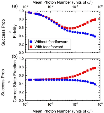
Some of the authors of this work have previously demon-strated improvements to the fidelity and correct state frac-tion by adding addifrac-tional postselecfrac-tion heralding condifrac-tions [19]; however, in that case, the improvements came at the cost of decreasing the success probability. Here we have shown a simultaneousimprovement to fidelity, correct state fraction, as well as the success probability with the addition of a feedforward mechanism. Presenting these parameters individually does not fully represent how significantly the active feedforward mechanism improves the characteristic SCAMP parameters. The combination of improved properties for the active feedforward mechanism means that we had higher-quality amplified states more often. To represent the improvement of the active feedforward mechanism over the inactive mechanism, the product of the success probability with fidelity and correct state fraction is plotted in Figs.3(a)
and 3(b), respectively. In Fig. 3, the improvement in the operation of the active feedforward SCAMP over the inactive is more evident than in Fig.2.
FIG. 2. State comparison amplifier characteristic parameters when the feedforward mechanism is active and inactive. The parameters of interest are (a) fidelity, (b) correct state fraction, (c) success probability, and (d) intensity gain. For all subfigures, the experimental data are represented by the points, while the dashed lines of the same color are the corresponding theoretical predictions. It can be seen in (a)–(c) that when the feedforward is active, there is an improvement to the parameters. In (d), the diversion of experimentally measured gain and theory is due to the nonlinear response caused by dead time of the single-photon detectors at very high count rates. The errors correspond to less than 2% of the actual values, and hence the data-point values cover the error bars.
success probability and correct state fraction data [Fig.3(b)] show that the two trends slowly diverge as |α|2 increases, similar to Fig.3(a); however, beyond |α|2=0.62, there is a more significant divergence.
Application of the technique to higher-dimensional encod-ing will require additional feedforward loops to cope with an increased rate of incorrectly chosen guess states. In the current configuration of fiber-based interferometers, this will be a complex task leading to, for example, more significant issues caused by environmentally induced instability. These problems could be addressed, in part, via improved adaptive mechanisms for stabilization control. In the longer term, the application to higher-dimensional encoding will require a change of platform to a chip-based configuration [38] to reduce significantly instabilities and problems associated with latency which are inevitably incurred in an optical-fiber-based configuration.
IV. CONCLUSIONS
Measurement and feedforward mechanisms that allow dy-namic quantum state correction could be a significant technol-ogy for large-scale quantum computation and long-distance quantum communication. In this paper, we have demonstrated a measurement and feedforward mechanism applied to the SCAMP, which allowed us to improve the key characteristic parameters of this nondeterministic amplifier. The
measure-ment and feedforward mechanism that we demonstrated was designed to capitalize on the SCAMP’s utilization of a dis-crete phase alphabet and initial state comparison stage. The mechanism had a latency of approximately 150 ns, which is comparable to other feedforward mechanisms demonstrated for similar applications [31,35].
We have presented the SCAMP in two experimental sce-narios, i.e., with and without the measurement and feedfor-ward mechanism active, which allowed us to demonstrate that the feedforward mechanism did have a highly beneficial effect on the amplifier performance. The improvements are starkly highlighted in the product of the success probability with either the fidelity or correct state fraction. In particular, we showed that above |α|2=0.62, there was a significant improvement to the amplifier properties. Experimental data match well with the theoretical model developed for analyzing the SCAMP. The only exception was the experimental mea-surement of the effective gain, which was degraded at high mean-photon numbers due to the nonlinearity of the SPAD detectors on the tomography stage.
With feedforward Without feedforward
Mean Photon Number (units of α2)
[image:5.608.323.548.72.186.2]Mean Photon Number (units of α2)
FIG. 3. The product of characteristic parameters of the state comparison amplifier when the feedforward mechanism is active and inactive. The difference between the success probability when the feedforward mechanism is active and inactive get significantly larger as|α|2 increases, illustrating the progressive improvement in per-formance by utilizing the measurement and feedforward approach. (a) The product of success probability and fidelity; (b) the product of success probability and correct state fraction.
All relevant data are available from the Heriot-Watt Uni-versity data archive [39].
ACKNOWLEDGMENTS
This work was supported by the Royal Society (UK), the Wolfson Foundation (UK), and the UK Engineering and Physical Sciences Research Council (EPSRC) through both Platform Grant No. EP/K015338/1 and the Quantum Com-munications Hub Grant No. EP/M013472/1.
APPENDIX A: EXPERIMENTAL SETUP AND METHODS
Figure4 shows the schematic diagram of the optical ex-perimental system used for this demonstration of the state comparison amplifier (SCAMP), which comprised three in-terferometers. The outermost interferometer provided a ref-erence coherent state for the final tomography measurement which was used to calculate the amplifier output state fidelity. The two inner interferometers were used to perform the two state comparison amplification stages. The nested interfer-ometer design was selected as it provided phase-matched pseudosources for the coherent states utilized as the signal, initial guess input, and second conditional guess. A deployed SCAMP system would seek to use independent phase-match coherent state sources, such as those regularly employed in measurement-device-independent quantum key distribution experiments.
An attenuated vertical-cavity surface-emitting laser (VC-SEL) was used as the weak-coherent source, which emitted
FIG. 4. The full optical schematic diagram for state comparison amplification with feedforward mechanism. Beam splitters (BS) in the experiment all had the reflection:transmission ratios as 50:50, except for BS1 which had ratios 90:10. Phase modulators (PM) were used to set the initial guess input and second conditional guess. Adjustable air gaps were used to maintain stability during the experiment, which allowed high visibility to be maintained during measurements. The optical system was constructed of polarization-maintaining components which were spliced together.
with a central wavelength of 849.80 nm and a spectral width of 0.05 nm. The narrow optical emission linewidth of the VCSEL simplified matching of relative path lengths since it offered a coherence length of a few cm. The operational wavelength was chosen as a compromise between the spectral response profiles of available single-photon detection tech-nology, tolerable losses (≈2.2 dB/km) of optical fiber for the short transmission distance, and the availability of high-quality linear-optical components. Commercially available thick-junction silicon single-photon avalanche diode (SPAD) detectors generally have high single-photon detection effi-ciency at the wavelength of 850 nm (≈40 %), with relatively low dark-count rates (of the order of tens to a few hundreds per second) and short detector dead time (less than 100 ns [37]). The commercially available thick-junction SPADs chosen for this experiment, denoted as D0, D1, DA, and DB in Fig. 4, have similar properties (i.e., detection efficiency, dark-count rate, linear response, and timing jitter) to each other. The coherent source was electrically pulsed at an operational frequency of 1 MHz, generating 1-ns-wide optical pulses. This operational frequency was chosen as it allowed the experiment to be analyzed under conditions where detector limitations, in terms of detector dead time and linear detector response, were minimized. This operational frequency also meant that higher-intensity optical states could be investi-gated. The electrical switch latency, explained later, was also a limiting factor for the operational frequency of the system reported in this paper. The light intensity from the laser was attenuated to the single-photon level using an in-fiber motor-ized attenuator, providing the quantum coherent states for the experiment.
The experimental system was constructed of 4.5μm core diameter single-mode polarization-maintaining optical fiber and bulk optical components to reduce experimental com-plexity. Polarization-maintaining fiber was chosen to avoid a requirement for polarization alignment elements in the experiment.
[image:5.608.64.282.74.311.2]and each optical path was time matched with the others, thereby allowing optimal performance of the amplifier. Beam splitter 1 (BS1) was used for the first state comparison mea-surement which interfered the initial guess input from the amplifier node, encoded using a lithium niobate (LiNbO3) phase modulator (PM), with the signal coherent state from the optical channel. The interference was monitored using SPAD D0. If SPAD D0 measured an event, it fed forward informa-tion onto a switching mechanism (described in AppendixB) which allowed the amplifier to set the second conditional guess. The amplifier then interfered the second conditional guess, encoded using a second LiNbO3PM, with the previous amplified state (from BS1) on BS2, which was monitored using SPAD D1. The optical output of the amplifier was then interfered with the reference coherent state on BS3; the interference of this final stage was monitored using SPADs DA and DB. The final tomography stage allowed the amplifier output state fidelity and an estimation of the intensity gain to be calculated.
Detector events measured on the SPADs were recorded with a picosecond resolution time-stamping module. The recorded detector events were partially processed and ana-lyzed during the experiment to enable vital active real-time stability monitoring and control of the interferometers, which allowed operation of the experiment over extended periods of time. The real-time stability mechanism monitored the visibility of the interferometers and tuned the experiment to high visibility by applying a voltage to expand or contract piezoelectric nanoposition actuators in each adjustable air gap, thereby fine tuning the relative optical path-length dif-ferences. Once the visibility of all interferometers was above a threshold value, the experiment recorded one of 25 measure-ments of one-second integration time of detector events across all detectors for each mean-photon number. The amplifier output was evaluated before each measurement of the set of 25 and only when the threshold conditions were met was a measurement recorded. If the visibility of any stage was below the threshold, recording measurements was paused until the thresholds were met again. The threshold visibility for each interferometer was≈96%, 80%, and 95% for measurements at BS1, BS2, and BS3, respectively. The visibilities were known, from previous work, to optimize the experiment.
After completion of the experiment, the recorded time-stamped data were postprocessed to identify coincidences and anticoincidences between detectors. To do this, the data were initially temporally filtered and gated, with a duration of ±2.5 ns around the expected photon arrival times. Then, 25 measurements were taken per data point to ensure statistical significance. The average and standard deviation of each set was then used in the analytical model, which is described in AppendixC. The model then provided data points for the figures and the associated errors.
APPENDIX B: FEEDFORWARD MECHANISM
[image:6.608.315.557.73.182.2]The main paper presents two experimental settings: no switching when there was a detection at D0, and switch correction when there was a detection at D0. In the first case, the switch mechanism was not active; therefore, the second conditional guess was always the same as the initial guess, i.e.,
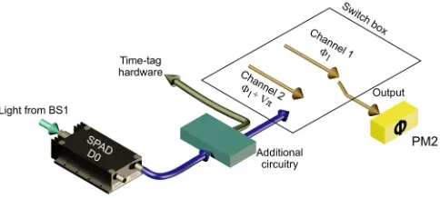
FIG. 5. Operation of the feedforward switch mechanism. Incom-ing photons from the first state comparison stage, beam splitter 1 (BS1), triggered the single-photon avalanche diode (SPAD). The electrical output of the detector was split to record photon arrival time and trigger the switch. The switch had two electrical inputs to set the second conditional guess. Channel 1 applied a voltage corresponding to the initial guess. Channel 2 applied a voltage corresponding to a change in initial guess byπ. The electrical output was connected to the second lithium-niobate phase modulator (PM2).
φ1. In the second case, the switch was active; therefore, when the D0 detector measured an event, it triggered the switch which changed the second conditional guess to φ1+Vπ, where Vπ corresponds to voltage that changes the phase byπ. For the second case, if no event was detected at D0, the second conditional guess was simply φ1. The second case operation allowed the system to correct for a possible incorrect guess. Figure5shows the schematic diagram of the switch mechanism which made the phase switching possible.
The feedforward mechanism used a fast response analog single-pole double-throw switch in solid-state electronics to apply aπ-phase change on the phase modulator for the length of its input trigger signal. The electrical output of SPAD D0, which monitored the initial state comparison stage (BS1), was used to triggered the switching mechanism to set the second conditional guess. The switch had two input signals; one carried an electrical signal equivalent to the initial guess to applyφ1to the second conditional guess. The second input signal carried an electrical signal equivalent toφ1+π.
The electrical process outlined in Fig.5had a total elec-trical latency of 150 ns. This latency was the summation of SPAD latency (≈20 ns), additional electrical circuitry (15 ns), and the switching box latency (≈115 ns). This required a minimum optical delay between the initial and second state comparison stage of 150 ns, which is equivalent to≈29 m of optical-fiber length. In practice, an optical delay of≈36 m (≈187 ns) was used. This allowed for any additional elec-trical delays to be accounted for, such as the elecelec-trical delay in the second conditional guess PM circuit. Figure 4 shows the positions of the optical delays in the optical system. The 36-m-long interferometer arms lead to increased instabili-ties of the interferometer, and hence the requirement for autonomous stabilization and visibility thresholds in the ac-quisition code.
source emitted negligible light in between the 1 MHz laser pulses. The dark-count rate on the commercially available sil-icon SPADs used was approximately 420 counts per second, which limited the unwanted switching. The detector was also isolated from external sources of ambient light.
APPENDIX C: FEEDFORWARD SCAMP THEORY
In this section, we will review the working principles of the SCAMP and highlight how the feedforward state correction improves its performance. We present our methods for a two-dimensional state space, but this can be generalized to a larger state space. Alice picks an input state|αfrom the set {| +α,| −α}uniformly and at random. Assume that Bob uses, as input guess for the first state comparison beam splitter, the state|β = | +t1r
1α; if Alice has picked ¯α= +α, then no
light will fall upon the photon detector in the Geiger mode. On the other hand, if Alice has chosen ¯α= −α, coherent light will fall upon the detector and it may or may not trigger. Let us now assume the comparison detector did not fire, i.e., D0=✗; we denote the unknown output state in the undetected arm as|σ¯(S,α¯). Using Bayes theorem, one can work out the probability that Bob’s guess was right and consequently that the output contains the amplified state| +α/r1as
P( ¯α= +α|D0=✗)=P( ¯σ(S,α¯)= +α/r1|D0=✗)
= P(D0 =✗|α¯ = +α)P( ¯α= +α) P(D0=✗)
, (C1)
where
P(D0=✗)= ¯
α=±α
P(D0=✗|α¯)P( ¯α). (C2)
The detection probabilities can be computed via the Kelley-Kleiner formula [40]. One can see that P( ¯σ(S,α¯)= +α/r1|D0=✗)>1/2 when Bob chooses |β as his guess, and thus the lack of triggers at the comparison detector is an imperfect indication that the output contains the amplified sate. The indication is imperfect as the detector might not trigger even if light falls upon it, as is the situation in which it fails to identify a wrong guess.
Bob can now further test his guess at the second compar-ison stage by suitably choosing another input coherent state. More precisely, as the first detector did not trigger, Bob does not have any reason to believe his initial guess is wrong. Thus, he will use the state| + t2
r1r2αto further amplify the state from
the first state comparison stage. As before, the lack of trigger at the second detector is an imperfect indication that Bob’s guess is right and that the output of the SCAMP contains the amplified state| +α/(r1r2). On the other hand, if the second detector triggers, i.e.,D1=✓, Bob will know that his initial guess was wrong and will disregard the output. The device gain is thus given byG=1/(r1r2).
Suppose now that the first detector does fire; then Bob unambiguously knows that his guess was wrong but he can still correct the final output from the second beam splitter if the device allows him to choose the appropriate input coherent state for the second comparison stage. Note that in this case, the output of the second detector should be disregarded as it does not provide useful information.
In summary, Bob will declare success and postselect the state if the two detectors do not register any event or if the first one does,
S={{D0=✗,D1 =✗},D0=✓} = {{✗0,✗1},✓0}. (C3)
The improvement with respect to a single comparison stage is apparent as this mechanism allows one to augment the successful scenarios with an unambiguous case, i.e., when the first detector fires. Thus, not only will the feedforward SCAMP have a higher success rate, but also a better output quality on average.
APPENDIX D: FEEDFORWARD SCAMP IMPLEMENTATION
As illustrated in Appendix C, a trigger provides an un-ambiguous indication that Bob’s guess is to be ruled out. However, it should be noted that this holds only for an ideal apparatus. An experimental implementation will be affected, for example, by mismatch in the length of the interferometric arms, causing an additional relative phase (eiφi) between the
input and the guess state; this in turn causes some light to reach the detector even when Bob’s guess is right. If the de-tector fires under this circumstance, it will trigger an unwanted state correction and, in the end, Bob will postselect an output that does not contain the amplified state, thus impairing the performance of the device. On the other hand, if the phase mismatch is small, as in our experiment, its effect is small and the same postselection criteria as for the ideal case are still meaningful, even if some of the triggers at the first detector happen when Bob’s guess is right.
In this experiment, the correction mechanism introduces a π shift on the phase of the second guess state. As a result of this, the device’s output when the correction is triggered is given by the state| −α(1−2r2
2t12)/(r1r2). Note that the latter amplitude is negative (ifαis real and positive) since 2r2
2t12is smaller than 1.
Finally, by considering the interferometric mismatch, we have that the target states for the noncorrection and correction scenario are given by
σ✗0,✗1 =
eiφ1t2
1 +r12
eiφ2t2
2 +r22
r1r2 α
, (D1)
|σ✓1 =
−t22eiφ2
eiφ1t2
1 +r12
−r2 2
eiφ2t2
2−r22
r1r2 α
. (D2)
APPENDIX E: FIGURES OF MERIT
The overallsuccess probabilityof the feedforward SCAMP is given by the sum of the probabilities of the events according to which Bob accepts the outcome. Assuming that Bob has chosen the inputs as specified in the previous section, the success probability is given by
P(S)=P(D0=✗,D1=✗)+P(D0=✓)
=
¯
α=±α
P(D0 =✗,D1=✗|α¯)P( ¯α)
+
¯
α=±α
The correct state fraction is the probability that the SCAMP output contains a correctly amplified state given success:
P(R|S)=P(R,S) P(S) =
¯
α=±α
P(σS|S,α¯)P(S|α¯)P( ¯α)
P(S)
=P(✗0,✗1| +α)P(+α)+P(✓0| −α)P(−α)
P(S) , (E2)
where, for the last equality, we made use of the following relations:
P(σ✗0,✗1|✗0,✗1,+α)=1,
P(σ✗0,✗1|✗0,✗1,−α)=0,
P(σ✓0|✓0,+α)=0,
P(σ✓0|✓0,−α)=1.
These relations can be interpreted as follows: (1) if both detectors do not trigger, the device’s output contains the amplified state only if Bob’s guess was right, and (2) if the first detector triggers, the output contains the amplified state only if the Bob’s guess was wrong.
Another quantity to assess the setup quality is the correct state fraction, postselected on the trigger of the first detector,
P(R|✓0)= P(R,✓0) P(✓0)
= P(✓0| −αP(✓0| −α)P(−α)
)P(−α)+P(✓0| +α)P(+α). (E3)
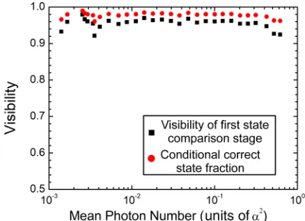
As mentioned in the previous section, in the ideal case a correct guess from Bob would not trigger the detector as there is destructive interference in that arm. However, if there is an interferometric mismatch at the first beam splitter, this is no longer necessarily true. This effect is small if the visibility is high at the correlation of these two effects, which is shown in Fig.6.
Thefidelityis the probability of passing a measurement test with the device’s output against the designated target state, given success:
F =P(T,S)= P(T,S) P(S) =
¯
α=±α
P(T|S,α¯)P(S|α¯)P( ¯α) P(S)
=
¯
α=±α
|σ¯(S,α¯)|σS|2P(S|α¯)P( ¯α)
P(S)
= 1
P(S)[P(✗0,✗1| +α)P(+α)+P(✓0| −α)P(−α) + |σ¯(✗0,✗1,−α)|σ✗0,✗1|
2P(✗0,✗1| −α)P(−α) + |σ¯(✓0,+α)|σ✓0|
2P(✓0| +α)P(+α)]. (E4)
The last expression is given by the weighted sum of the over-laps between the output state and the appropriate target states. These quantities can be readily computed for a single comparison stage as well. It should be noted that the
compar-FIG. 6. The interferometric visibility at the first state comparison stage and the conditional correct state fraction. This plot shows that the visibility of the first state comparison stage and the conditional correct state fraction are related. If the visibility of the first state comparison stage were to reduce, so would the conditional correct state fraction.
[image:8.608.324.543.70.229.2]ison between the two different devices (single SCAMP and feedforward SCAMP) should involve correct state fraction and fidelity multiplied by the respective probability. This is required in order to have a fair comparison as the success probability of the feedforward SCAMP is always higher than that with a single comparison stage and, when success is achieved, the output quality is better as well. This comparison is presented in Figs.3(a) and3(b) in the main text, which showed the cross product of the success probability with the correct state fraction and fidelity, respectively. Figure7 high-lights the relative improvement of the feedforward operation over the nonfeedforward one.
[image:8.608.323.541.494.662.2] [image:8.608.61.291.548.675.2][1] B. Korzh, C. C. W. Lim, R. Houlmann, N. Gisin, M. J. Li, D. Nolan, B. Sanguinetti, R. Thew, and H. Zbinden, Provably secure and practical quantum key distribution over 307 km of optical fibre,Nat. Photon.9,163(2015).
[2] H.-L. Yin, T.-Y. Chen, Z.-W. Yu, H. Liu, L.-X. You, Y.-H. Zhou, S. J Chen, Y. Mao, M.-Q. Huang, W.-J. Zhang, H. Chen, M. J. Li, D. Nolan, F. Zhou, X. Jiang, Z. Wang, Q. Zhang, X. B. Wang, and J.-W. Pan, Measurement-Device-Independent Quantum Key Distribution Over a 404 km Optical Fiber,Phys. Rev. Lett.117,190501(2016).
[3] R. J. Collins, R. Amiri, M. Fujiwara, T. Honjo, K. Shimizu, K. Tamaki, M. Takeoka, M. Sasaki, E. Andersson, and G. S. Buller, Experimental demonstration of quantum digital signatures over 43 dB channel loss using differential phase shift quantum key distribution,Sci. Rep.7,3235(2017).
[4] R. J Donaldson, R. J. Collins, K. Kleczkowska, R. Amiri, P. Wallden, V. Dunjko, J. Jeffers, E. Andersson, and G. S. Buller, Experimental demonstration of kilometer-range quantum digi-tal signatures,Phys. Rev. A93,012329(2016).
[5] C. M. Caves, Quantum limits on noise in linear amplifiers,Phys. Rev. D26,1817(1982).
[6] T. C. Ralph and A. P. Lund, Nondeterministic noiseless linear amplification of quantum systems, inQuantum Communication, Measurement and Computing (QCMC): Ninth International Conference on QCMC, edited by A. Lvovsky, AIP Conf. Proc. No. 1110 (AIP, New York, 2009), p. 155.
[7] D. T. Pegg, L. S. Phillips, and S. M. Barnett, Optical State Truncation by Projection Synthesis,Phys. Rev. Lett.81,1604
(1998).
[8] M. Curty and T. Moroder, Heralded-qubit amplifiers for practi-cal device-independent quantum key distribution,Phys. Rev. A
84,010304(2011).
[9] P. Marek and R. Filip, Coherent-state phase concentration by quantum probabilistic amplification,Phys. Rev. A81,022302
(2010).
[10] M. A. Usuga, C. R. Müller, C. Wittmann, P. Marek, R. Filip, C. Marquardt, G. Leuchs, and U. L. Andersen, Noise-powered probabilistic concentration of phase information,Nat. Phys.6,
767(2010).
[11] C. R. Müller, C. Wittmann, P. Marek, R. Filip, C. Marquardt, G. Leuchs, and U. L. Andersen, Probabilistic cloning of coherent states without a phase reference,Phys. Rev. A86,010305(R)
(2012).
[12] J. Fiurášek, Engineering quantum operations on traveling light beams by multiple photon addition and subtraction,Phys. Rev. A80,053822(2009).
[13] C. I. Osorio, N. Bruno, N. Sangouard, H. Zbinden, N. Gisin, and R. T. Thew, Heralded photon amplification for quantum communication,Phys. Rev. A86,023815(2012).
[14] N. Gisin, S. Pironio, and N. Sangouard, Proposal for Imple-menting Device-Independent Quantum Key Distribution Based on a Heralded Qubit Amplifier,Phys. Rev. Lett.105,070501
(2010).
[15] H. M. Chrzanowski, N. Walk, S. M. Assad, J. Janousek, S. Hosseini, T. C. Ralph, T. Symul, and P. K. Lam, Measurement-based noiseless linear amplification for quantum communica-tion,Nat. Photon.8,333(2014).
[16] E. Eleftheriadou, S. M. Barnett, and J. Jeffers, Quantum Optical State Comparison Amplifier, Phys. Rev. Lett. 111, 213601
(2013).
[17] R. J. Donaldson, R. J. Collins, E. Eleftheriadou, S. M. Barnett, J. Jeffers, and G. S. Buller, Experimental Implementation of a Quantum Optical State Comparison Amplifier,Phys. Rev. Lett.
114,120505(2015).
[18] U. Zanforlin, R. J. Donaldson, L. Mazzarella, R. J. Collins, J. Jeffers, and G. S. Buller, Quantum optical state comparison amplification of coherent states, inProceeding of SPIE(SPIE, 2018), Vol. 10674, p. 1067413.
[19] R. J. Donaldson, L. Mazzarella, R. J. Collins, J. Jeffers, and G. S. Buller, A high-gain and high-fidelity coherent state com-parison amplifier,Commun. Phys.1,54(2018).
[20] R. Prevedel, P. Walther, F. Tiefenbacher, P. Böhi, R. Kaltenbaek, T. Jennewein, and A. Zeilinger, High-speed linear optics quan-tum computing using active feed-forward, Nature (London)
445,65(2007).
[21] K. Chen, C. M. Li, Q. Zhang, Y. A. Chen, A. Goebel, S. Chen, A. Mair, and J. W. Pan, Experimental Realization of One-Way Quantum Computing with Two-Photon Four-Qubit Cluster States,Phys. Rev. Lett.99,120503(2007).
[22] K. Nemoto and W. J. Munro, Nearly Deterministic Linear Optical Controlled-NOT Gate, Phys. Rev. Lett. 93, 250502
(2004).
[23] T. B. Pittman, B. C. Jacobs, and J. D. Franson, Demonstration of feed-forward control for linear optics quantum computation,
Phys. Rev. A66,052305(2002).
[24] G. J. Mendoza, R. Santagati, J. Munns, E. Hemsley, M. Piekarek, E. Martín-López, G. D. Marshall, D. Bonneau, M. G. Thompson, and J. L. O’Brien, Active temporal and spatial multiplexing of photons,Optica3,127(2016).
[25] M. J. Collins, C. Xiong, I. H. Rey, T. D. Vo, J. He, S. Shahnia, C. Reardon, T. F. Krauss, M. J. Steel, A. S. Clark, and B. J. Eggleton, Integrated spatial multiplexing of heralded single-photon sources,Nat. Commun.4, (2013).
[26] A. L. Migdall, D. Branning, and S. Castelletto, Tailoring single-photon and multisingle-photon probabilities of a single-single-photon on-demand source,Phys. Rev. A66,053805(2002).
[27] L. Mazzarella, F. Ticozzi, V. Sergienko, A. G. Vallone, and P. Villoresi, Asymmetric architecture for heralded single-photon sources,Phys. Rev. A88,023848(2013).
[28] T. Meany, L. A. Ngah, M. J. Collins, A. S. Clark, R. J. Williams, B. J. Eggleton, M. J. Steel, M. J. Withford, O. Alibart, and S. Tanzilli, Hybrid photonic circuit for multi-plexed heralded single photons, Laser Photon. Rev. 8, L42
(2014).
[29] F. Kaneda, J. J. Christensen, B. G. and Wong, H. S. Park, K. T. McCusker, and P. G. Kwiat, Time-multiplexed heralded single-photon source,Optica2,1010(2015).
[30] C. Xiong, X. Zhang, Z. Liu, M. J. Collins, A. Mahendra, L. G. Helt, M. J. Steel, D. Y. Choi, C. J. Chae, P. H. W. Leong, and B. J. Eggleton, Active temporal multiplexing of indistinguishable heralded single photons, Nat. Commun. 7, (2016).
[31] J. Sabines-Chesterking, R. Whittaker, S. K. Joshi, P. M. Birchall, P. A. Moreau, A. McMillan, H. V. Cable, J. L. O’Brien, J. G. Rarity, and J. C. F. Matthews, Sub-Shot-Noise Transmission Measurement Enabled by Active Feed-Forward of Heralded Single Photons, Phys. Rev. Appl. 8,
049902(2017).
A. Wallraff, Deterministic quantum teleportation with feed-forward in a solid state system, Nature (London) 500, 319
(2013).
[33] X. Ma, T. Herbst, T. Scheidl, D. Wang, S. Kropatschek, W. Naylor, B. Wittmann, A. Mech, J. Kofler, E. Anisimova, V. Makarov, T. Jennewein, R. Ursin, and A. Zeilinger, Quantum teleportation over 143 kilometres using active feed-forward,
Nature (London)489,269(2012).
[34] X. Jin, J. Ren, B. Yang, Z. Yi, F. Zhou, X. Xu, S. Wang, D. Yang, Y. Hu, S. Jiang, T. Yang, H. Yin, K. Chen, C. Peng, and J. Pan, Experimental free-space quantum teleportation,Nat. Photon.4,
376(2010).
[35] Y. Salathé, P. Kurpiers, T. Karg, C. Lang, C. K. Andersen, A. Akin, S. Krinner, C. Eichler, and A. Wallraff, Low-Latency Digital Signal Processing for Feedback and Feedforward in Quantum Computing and Communication,Phys. Rev. Appl.9,
034011(2018).
[36] L. Mazzarella, R. J. Donaldson, R. J. Collins, U. Zanforlin, G. Tatsi, G. S. Buller, and J. Jeffers, Quantum state comparison amplifier with feedforward state correction, inProceeding of SPIE(SPIE, 2018), Vol. 10674, p. 106741D.
[37] G. S. Buller and R. J. Collins, Single-photon generation and detection,Meas. Sci. Technol.21,012002(2010).
[38] J. W. Silverstone, D. Bonneau, J. L. O’Brien, and Thompson M. G., Silicon quantum photonics,IEEE J. Sel. Top. Quantum Electron.22,390(2016).
[39] R. J. Donaldson, L. Mazzarella, U. Zanforlin, R. J. Collins, J. Jeffers, and G. S. Buller, Data cite for “Quantum state cor-rection using a measurement-based feedforward mechanism”,
https://doi.org/10.17861/ad53d56d-fb18-4f56-824e-28f586 aacce4(2019).
[40] P. L. Kelley and W. H. Kleiner, Theory of electromagnetic field measurement and photoelectron counting,Phys. Rev.136,