Different Options for Multi-Rotor Wind Turbine Grid
Connection
K Givaki*
* Department of Electronic & Electrical Engineering, University of Strathclyde, Glasgow, United Kingdom
Keywords: Multi-rotor wind turbine, Grid integration, Voltage source converters, Renewable energies.
Abstract
In this paper, different options for integration of the multi-rotor wind turbine concept is investigated. The intra-turbine collection network of the multi-rotor wind turbine can be designed in either AC or DC. The reliability and costs associated with each connection option are compared. It is presented that the multi-rotor wind turbine can be considered as wind farm with the same number of turbines and the same configuration for collection network as for wind farms can be used for MRWT.
1 Introduction
Wind turbines are one of the main renewable energy resources. In the Europe, the wind counts for 51% of the newly installed power capacity in 2016. By the end of 2016, wind energy is the second largest technology for power generation and the largest renewable generation with for 17% of the total installed power generation capacity [1]. Around 12.5 GW of the total installed wind capacity is offshore wind, and the total installed offshore capacity is expected to increase to around 25GW by the end of 2020[2]. As the amount of the wind generation increases, the need for larger wind turbines for generating more power is increased. The generated energy by the wind turbine relates to swept area. Therefore, in order to have a wind turbine rated at few tens of MW, huge blades need to be constructed. For very large wind turbines, the output energy is related to the square of the blade size but the mechanical stress on the structure will increase in third power of diameters. Different mechanical issues will arise with very large wind turbines[3, 4], that increase the cost of energy production by the turbine.
In order to generate very large amount of power by the turbines instead of using a very large rotor, few smaller rotor can be used in the wind turbine. By maintain the swept area of the wind turbine constant the same amount of energy can be produced by the wind turbine. This will reduce the overall mass of rotor[4], hence, the cost of energy.
Furthermore, by using multi rotor wind turbine the reliability of the overall system will be improved compared to the large wind turbine as a fault in one turbine of the multi rotor system will not cause the loss of all wind turbine power.
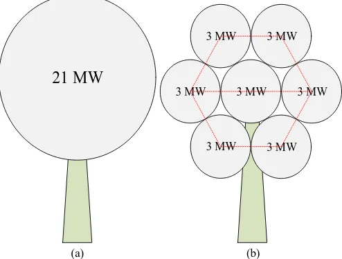
In the relevant literature, few dual or multi-rotor wind turbine (MRWT) structures are studied [4-7] and Vestas built a concept demonstrator multi-rotor wind turbine in 2016. Fig. 1 shows an example model of a multi-rotor wind turbine concept in comparison with a conventional one.
So far, the main focus of the literature were on the mechanical feasibility of the multi-rotor wind turbines and grid connection and electrical circuit design of the multi-rotor wind turbines are not considered.
The rest of this paper is organised as follows: the most appropriate wind turbine configuration for multi-rotor system is discussed in section 2. In section 3, different electrical design and grid connection options are presented in section 3. Finally, conclusion and discussion about different connection option is presented in section 4.
21 MW
(a) (b)
3 MW 3 MW
3 MW 3 MW
3 MW
3 MW 3 MW
Fig. 1. An example of multi-rotor wind turbine
AC
DC
DC AC
Grid Transformer
Gearbox
Wind
Generator
[image:1.595.305.552.380.567.2]Drive train-1 Drive train-2
33/132kV
P Q 0.69/33kV
Drive train-1
0.69/33kV
Drive train-1
0.69/33kV
Drive train-1
0.69/33kV
Drive train-1
0.69/33kV
Drive train-1
0.69/33kV
Drive train-1
33/132kV
P Q 0.69/33kV
Drive train-1
0.69/33kV
Drive train-1
0.69/33kV
Drive train-1
33/0.69kV
Drive train-1
33/0.69kV
Drive train-1
33/0.69kV
Drive train-1
0.69/33kV
Drive train-1
0.69/33kV
Drive train-1
0.69/33kV
Drive train-1
33/0.69kV
Drive train-1
33/0.69kV
Drive train-1
33/0.69kV
Drive train-1
33/132kV
P Q 0.69/33kV
Drive train-1
0.69/33kV
Drive train-1
0.69/33kV
Drive train-1
0.69/33kV
Drive train-1
0.69/33kV
Drive train-1
0.69/33kV
Drive train-1
(a). Radial connection
33/132kV
P Q
Drive train-1
0.69/33kV
Drive train-1
0.69/33kV
Drive train-1
0.69/33kV
Drive train-1
0.69/33kV
Drive train-1
0.69/33kV
0.69/33kV
Drive train-1
(d). Star connection
(c). Two sided ring connection
[image:2.595.99.499.81.614.2](b). One sided ring connection
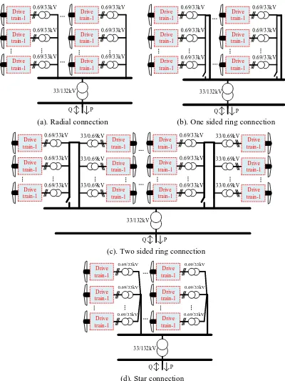
Fig.3. different AC collection network for a multi-rotor wind turbine
2 Wind turbine drive-train options
Different types of wind turbines have been utilised in last few decades and can generally be categorised into fixed speed and variable speed turbines
[8]
. Fixed speed wind turbines use induction generators with a squirrel cage rotor.Variable speed wind turbines, in general, use power electronic converters between the turbine and grid which allow the turbine to operate over a wide range of rotational speeds [8].
AC
DC
Drive train-2
Drive train-2 Drive
train-2
Drive train-2
Drive train-2
Drive train-2
+
+
+
+
+
+
Transformer
GRID
Drive train-2 Drive train-2
Drive train-2
AC
DC
GRID
+
+
+
+
Drive train-2 Drive train-2
Drive train-2
+
+
+
+
Drive train-2 Drive train-2
Drive train-2
+
+
+
+
AC
DC
Transforme rGRID
(a). DC radial connection
[image:3.595.96.515.86.424.2](b). DC series connection
(b). DC series-parallel connection
Fig.4. different DC collection network for a multi-rotor wind turbine
Hence, FRC wind turbine are the best option to comply with grid code requirements due to presences of the fully rated converters between grid and generator [10].
Furthermore, the reliability and availability of the selected wind turbine configuration for MRWT system needs to be considered during the designing process. As seen Fig. 2, the FRC wind turbine can either use gear-box or be direct drive (gearless). The direct drive wind turbines provides higher reliability compared to the geared option as it has less mechanical parts, avoids failures of gearbox, and does not need gear-box maintenance [9].
Therefore, to provide all the aforementioned operational and reliability requirements, permanent magnet synchronous generator (PMSG) based direct drive wind turbine is selected for multi rotor wind turbine applications. The PM synchronous generators provides higher efficiency, improved thermal characteristics, higher reliability, and better energy yield compared to an electrically excited machine [11].
3 grid Connection options
In this section, different intra-turbine electrical circuit and grid connection options for a MRWT system are presented and compared. The reliability and cost can be considered as the decision factors for selecting the intra-turbine circuit for the MRWT system.
The circuit layout of MRWT depends on the number of small turbines in the MRWT. Generally, the MRWT system can be considered as one or few clusters of wind turbine in a conventional wind farm. Therefore, the intra-turbine circuit of the MRWT system can be designed similar to the intra-array circuit of a wind farm. The
In wind farms, to enhance the overall reliability of the system, few wind turbines are grouped in clusters [12] and combination of all clusters forms the collection network of the Wind farm. The same approach can be used in an MRWT system. Therefore, similar to a wind farm, the collection network for a MRWT system can be designed in both AC and DC.
It should be mentioned that number of turbines in
Note that in Fig. 2, for ease of demonstrations in rest of papers, two different drive-train options are shown. The output of “drive-train 1” in Fig. 2 is the AC voltage of the back to back converter. Furthermore, in Fig. 2, the “drive-train 2” consists of the mechanical parts, generator and a converter so that the output of “drive-train 2” is DC voltage.
3.1 AC connection options
turbines in MRWT, reliability level, etc. [13]. These options are divided into 3 main groups as follows:
A. Radial Connection
As is seen in Fig. 3 (a), it is the simplest layout for intra-turbine electrical circuit and grid connection of MRWT system. As seen in Fig. 3 (a), this layout does not provide any additional power path. Hence, in case of fault occurrence in the system, the downstream turbines will be disconnected from the grid. Therefore, this configuration does not provide a high level of reliability [12, 14].
B. Ringed Connections
As seen in schematic in Figs. 3 (b) and 3 (c), the employment of ringed configuration layouts provide additional power flow path. Therefore, the overall reliability of system is improved compared to radial connection. These configuration are simply the radial but for one sided ring (Fig. 3 (b)) the additional power flow path is added by adding an extra cable to connect the last turbine in the string to the cluster bus-bar, however, for two sided ring configuration (Fig. 3 (c)) the last turbines of two adjacent strings are connected to each other. These two configurations provide greater level of reliability compared to radial configuration. However, as for the one sided ring, an additional cable is employed, it will be more costly compared to radial configuration. Furthermore, for two-sided ringed configuration, the cables need to be sized in the way that they can tolerate total current of the adjacent string, which makes it more expensive compared to radial configuration [12].
C. Star Connection
As seen in Fig. 3 (d), in star configuration, each cable is transferring the power from one turbine. Therefore, the cable sizes are reduced. If a failure happens in one turbine, the other turbines will still be able to transfer power to the grid. Therefore, this configuration provides high level of reliability[12]. As the size of cables are reduced, the cost for this configuration is reduced.
3.2 DC connection options
In this section, DC configurations for intra-turbine collection network of MRWT is presented. Fig. 4 shows different possible DC options for electrical circuit of a MRWT. The power generated by generator will be rectified to DC as shown in “Drive-train 2” of Fig. 2. Then, the output of the rectifier will be used as the DC input for the electrical collection network of MRTW. One of the main reasons for wind turbine failure is the power electronic converters [15], therefore, as by using the DC collection network the number of converters is reduced, the overall reliability of the system will increase.
Fig. 4 (a) shows the DC radial topology, output of the wind turbines are connected through different cables and a converter is used to invert DC voltage to AC and then a transformer steps up the voltage for grid integration. On the other hand, instead of the rectifier and transformer, it is possible to use a DC/DC converter to step up the DC voltage
and form a DC collection network for a wind farm consisting of multiple MRWT system.
Fig. 4 (b) shows the configuration in which each of the wind turbines in MRWT system are connected in series [14]. Hence, the voltage of DC link will be increased. Therefore, step up transformer (or DC/Dc converter) might not be needed or grid connection. This will decrease the overall cost of the system. on the other hand, in the case of fault each turbine will see higher stress, therefore, it is required to use higher rating insulation that will increase the price. This will be more investigated in the follow-up studies.
In Fig. 4 (c), series connection of turbines is used to increase voltage level to the transmission voltage level. To increase the power output of the MRWT, various number of series string can be connected together. This configuration has the same advantages and disadvantages as the previous configuration.
4 Conclusions
This paper presents the initial stage research results on the grid connection of Multi rotor wind turbine system. Generally, the electrical collection network of a MRWT system can be considered as a collection network of a wind turbine and the same approaches as for the wind farm can be used for MRWT system. The main difference between collection network of a wind farm and MRWT is the space that is needed for grid connection. In a MRWT structure there is limited space and also the structural stress needs to be considered for designing the most efficient and reliable MRWT system. This paper is the results of the primarily stage of the research on this topic and it is trying to be more informative for the power engineering and renewable energy research community.
Acknowledgements
This work is supporter in part by the EPSRC, project reference number EP/G037728/1S.
References
[1] WindEurope, "Wind in Power-2016 European Statistics," Wind Europe Business Intelligence2017. [2] WindEurope, "The European Offshore Wind
Industry-Key Trends and Statistics 2016," WindEurope2017.
[3] P. Jamieson, Innovation in Wind Turbine Design, 1 ed.: John Wiley & Sons, Ltd, 2011.
[4] P. Jamieson and M. Branney, "Multi-Rotors; A Solution to 20 MW and Beyond?," Energy Procedia, vol. 24, pp. 52-59, 2012/01/01/ 2012.
[5] A. Rosenberg, S. Selvaraj, and A. Sharma, "A Novel Dual-Rotor Turbine for Increased Wind Energy Capture," Journal of Physics: Conference Series, vol. 524, p. 012078, 2014.
[6] L. Seungbae, "Dual Rotor Wind Turbine," patent, 2009.
multi-rotor concept," Journal of Physics: Conference Series, vol. 524, p. 012084, 2014.
[8] O. Anaya-Lara, D. Campos-Gaona, E. Moreno-Goytia, and G. Adam, Offshore Wind Energy Generation Control, Protection, and Integraion to Electrical Systems: John Wiley & Sons, Ltd, 2014. [9] H. Polinder, J. A. Ferreira, B. B. Jensen, A. B.
Abrahamsen, K. Atallah, and R. A. McMahon, "Trends in Wind Turbine Generator Systems," IEEE Journal of Emerging and Selected Topics in Power Electronics, vol. 1, pp. 174-185, 2013.
[10] S. Zhang, K. J. Tseng, D. M. Vilathgamuwa, T. D. Nguyen, and X. Y. Wang, "Design of a Robust Grid Interface System for PMSG-Based Wind Turbine Generators," IEEE Transactions on Industrial Electronics, vol. 58, pp. 316-328, 2011.
[11] H. Li and Z. Chen, "Overview of different wind generator systems and their comparisons," IET Renewable Power Generation, vol. 2, pp. 123-138, 2008.
[12] K. Givaki, D. Chen, and O. Anaya-Lara, "Stability studies of different AC collection network topologies in wind farms," presented at the International Conference on Renewable Power Generation, London, 2016.
[13] D. W. Elliott, S. J. Finney, and C. Booth, "Single Converter Interface for a Cluster of Offshore Wind Turbines," in IET Conference on Renewable Power Generation 2011, pp. 1-6.
[14] H. J. Bahirat, B. A. Mork, and H. K. Hoidalen, "Comparison of Wind Farm Topologies for Offshore Applications," in IEEE Power and Energy Society General Meeting, San Diego, 2012.