This is a repository copy of Transient propagation dynamics of flowing plasmas accelerated by radio-frequency electric fields.
White Rose Research Online URL for this paper: http://eprints.whiterose.ac.uk/116712/
Version: Accepted Version
Article:
Dedrick, James Peter orcid.org/0000-0003-4353-104X, Gibson, Andrew Robert
orcid.org/0000-0002-1082-4359, Rafalskyi, Dmytro et al. (1 more author) (2017) Transient propagation dynamics of flowing plasmas accelerated by radio-frequency electric fields. Physics of Plasmas. pp. 1-5. ISSN 1089-7674
https://doi.org/10.1063/1.4983059
[email protected] https://eprints.whiterose.ac.uk/
Reuse
Items deposited in White Rose Research Online are protected by copyright, with all rights reserved unless indicated otherwise. They may be downloaded and/or printed for private study, or other acts as permitted by national copyright laws. The publisher or other rights holders may allow further reproduction and re-use of the full text version. This is indicated by the licence information on the White Rose Research Online record for the item.
Takedown
If you consider content in White Rose Research Online to be in breach of UK law, please notify us by
Transient propagation dynamics of flowing plasmas accelerated by
radio-frequency electric fields
James Dedrick
York Plasma Institute, University of York, YO10 5DD York, UK
Andrew Robert Gibson
York Plasma Institute, University of York, YO10 5DD York, UK and LPP-CNRS, Ecole Polytechnique, route de Saclay, 91120 Palaiseau, France
Dmytro Rafalskyi and Ane Aanesland
LPP-CNRS, Ecole Polytechnique, route de Saclay, 91120 Palaiseau, France
Flowing plasmas are of significant interest due to their role in astrophysical phenomena and
potential applications in magnetic-confined fusion and spacecraft propulsion. The acceleration of
a charge-neutral plasma beam using the radio-frequency self-bias concept could be particularly
useful for the development of neutralizer-free propulsion sources. However, the mechanisms that
lead to space-charge compensation of the exhaust beam are unclear. Here, we spatially and
tem-porally resolve the propagation of electrons in an accelerated plasma beam that is generated using
the self-bias concept with phase-resolved optical emission spectroscopy. When combined with
measurements of the extraction-grid voltage, ion and electron currents, and plasma potential, the
pulsed-periodic propagation of electrons during the interval of sheath collapse at the grids is found
The interesting fundamental physics of plasma acceleration [1–3], and its potential
appli-cations in thermonuclear fusion [4,5] and spacecraft propulsion [6–8] have driven significant
research interest. Gridded-ion and Hall-effect thrusters are now established propulsion
tech-nologies [9], and plasma thrusters that can operate without an external neutralizer are under
development [10, 11].
Using the Neptune plasma-thruster prototype, the acceleration of a broad, collimated and charge-neutral plasma beam, without the use of an external neutralizer, has recently
been demonstrated to exhibit comparable performance to traditional gridded-ion propulsion
sources [12,13]. Its design is based around the principle of plasma acceleration, whereby the
coincident extraction of ions and electrons is achieved by applying an oscillating electrical
field to the gridded acceleration optics. In traditional gridded-ion thrusters, ions are
accel-erated using a designated voltage source to apply a direct-current (dc) electric field between
the extraction grids. In this work, a dc self-bias voltage is formed when radio-frequency (rf)
power is coupled to the extraction grids due to the difference in area of the powered and
grounded surfaces in contact with the plasma.
To maximise thrust efficiency using a single rf power source, it is important to regulate the
electron and ion fluxes that vary on nanosecond time scales. Further, boundary conditions
in the plasma source and diffusion region can play a significant role in determining the
plasma propagation behaviour [14]. These require a more detailed understanding of the
beam dynamics with respect to distance, time and particle energy.
Non-invasive optical diagnostic techniques have previously proven useful to the
inves-tigation of electric propulsion sources, providing enhanced spatial resolution compared to
electrostatic probes. For example, optical emission spectroscopy has been used to measure
neutral-gas heating in electrothermal plasma thrusters [15], and imaging and laser induced
fluorescence velocimetry are effective for the study of cross-field electron transport [16] and
ion velocities [17] in Hall-effect thrusters.
Of particular importance to space-charge compensation in the Neptune beam are the spatially and temporally resolved electron dynamics at the extraction grids. Phase-resolved
optical emission spectroscopy (PROES), which enables the spatial and temporal dynamics of
selected excited species to be measured on nanosecond time scales [18, 19], has successfully
been applied to low-pressure [20–25] and atmospheric-pressure [26–28] capacitively coupled
electrons to determine their role in compensating space charge in the exhaust beam.
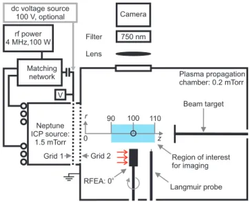
The experimental setup is shown in Figure 1. Neptune comprises an inductively coupled plasma source (ICP: Teflon-insulated 8×12×12 cm3 cavity, ferrite-enhanced 7-turn planar
antenna driven at 4 MHz, 2 mm thick ceramic window) operated in H-mode and two
rectan-gular extraction grids (stainless steel, optical transparency 0.6, aperture diameter 2.5 mm,
inter-grid distance 2 mm) that are used to accelerate ions.
Camera
Filter
Region of interest for imaging
Beam target Plasma propagation chamber: 0.2 mTorr Lens
Matching network rf power 4 MHz,100 W
Neptune ICP source:
1.5 mTorr z
Langmuir probe r
RFEA: 0o
90 100 110
Grid 2 Grid 1
V
750 nm
0 dc voltage source
100 V, optional
FIG. 1. Illustration of the experimental setup. For electrical measurements the beam target,
Lang-muir probe and retarding field energy analyser (RFEA) can be positioned at (r, z) = (0,100) mm
as shown by the open circle, and these are removed for measurements of the optical emission with
the camera. The RFEA can be rotated to face the plasma source (rotation angle 0◦ shown) or
in the r-direction (rotation angle 90◦). During ‘rf operation’, rf power is distributed between the
ICP coil and extraction grids. In ‘dc operation’, rf power is coupled to the ICP coil only and a dc
voltage source is connected across the grids.
During ‘rf operation’, rf power at 100 W is distributed between the ICP coil and
Grid 1 (closest to the cavity as shown in Figure 1) using an impedance matching network
and blocking capacitor, while Grid 2 is electrically grounded. These conditions correspond
to a time-varying, approximately sinusoidal voltage waveform at the extraction grids with
a peak-to-peak voltage V = 200 V and a time-averaged self-bias voltage Vsb = 100 V (see
Figure 4 (a) later). During ‘dc operation’ (described further below) rf power is coupled to
the ICP coil only and a 100 V dc voltage source is connected across the extraction grids.
2500 L/s pumping rate) and is fed with 25 sccm of argon. Under these conditions the
source pressure is 1.5 mTorr, while that in the propagation chamber is 0.2 mTorr.
An intensified charge coupled device camera (ICCD: Andor iStar 320T, 1024×256 pixel array, 26µm2
pixel area) is used to detect the optical emission from the plasma beam through
a view port in the propagation chamber. This enables a 20×7.5 mm2 region-of interest
that is axially elongated and centred at z = 100 mm as shown in Figure 1. The spatial
resolution of the optical measurements is determined to be 26.7 pixel/mm. Measurements
are undertaken using a 50 ns gate width and a 50 ns gate step. Images are acquired with a
sampling frequency of 500 kHz for an exposure time of 20 s. The observed optical emission
is therefore integrated over thousands of rf cycles to ensure reproducibility.
The ICCD is fitted with an interference filter for spectral discrimination. This has a
central wavelength 750 nm and full width at half maximum of 10 nm, and hence the
tran-sitions under consideration are Ar(2p1−1s2) at 750.4 nm and Ar(2p5−1s4) at 751.5 nm.
Cascade processes from higher-energy excited states into the Ar(2p1) level are understood
to have only a minor influence under these conditions, but could play a more significant
role for the Ar(2p5) level [29]. In the absence of cascade processes, the measured optical
emission is considered to be indicative of electrons with energy greater than 13.48 eV for
direct-impact excitation of the Ar(2p1) level. However, since we cannot exclude the optical
emission at 751.5 nm from the Ar(2p5) level, the contribution from cascade processes cannot
be neglected. If significant, this would result in an increase in the effective lifetime of the
optical emission and a decrease in the temporal variations observed.
For electrical measurements, a Langmuir probe (LP), rf-compensated retarding field
en-ergy analyser (RFEA), and floating beam target are positioned in the centre of the
region-of-interest at (r, z) = (0,100) mm as shown in Figure 1. These enable measurements of
the on-axis and isotropic electron energy probability functions (EEPFs), on-axis ion energy
distribution function (IEDF), together with the electron current, ion current and beam
po-tential with respect to time. For EEPF measurements, the LP is used to detect (isotropic)
electrons of energy 0< Ee <12 eV, and the RFEA can be rotated such that it faces the
source along the z-axis (0◦ rotation angle) or in the perpendicular r-direction (90◦
rota-tion angle) for collecrota-tion of directed and isotropic electron fluxes, respectively, of energy
12< Ee <21 eV.
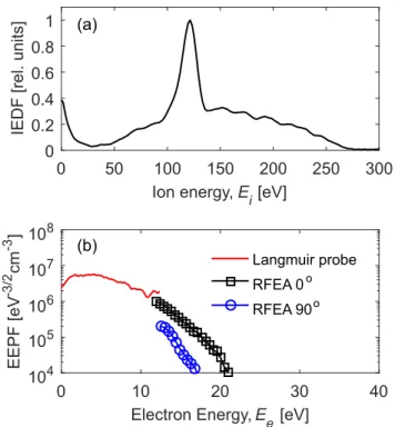
ob-served, which is consistent with the similar values of the 4 MHz grid voltage and ion-plasma
frequencies [30]. It is also in agreement with previous measurements, where multiple peaks
in the spectrum were suggested to be caused by a spatially varying sheath profile at the
multi-aperture extraction grids [12].
0 50 100 150 200 250 300 Ion energy,E
i[eV] 0 0.2 0.4 0.6 0.8 1 IEDF [rel. units]
0 10 20 30 40
Electron Energy,E e[eV] 104 105 106 107 108 EEPF [eV -3/2 cm -3 ] Langmuir probe
RFEA 0o
RFEA 90o
(a)
(b)
FIG. 2. (a) Ion energy distribution function (IEDF) and (b) electron energy probability
func-tions (EEPFs) measured with a Langmuir probe over 0-12 eV and 12-21 eV using a rotating
retarding field energy analyser (RFEA) during rf operation.
Measurements of the EEPF, shown in Figure 2 (b) for isotropic (LP, RFEA 90◦) and
on-axis (RFEA 0◦) orientations, demonstrate the presence of an anisotropic electron beam.
These electrons could be accelerated by a local reversal of the electric field during the Grid 1
sheath collapse [31]. As the electron beam is propagating in the same direction as the ion
flux the conditions are consistent with the presence of an accelerated plasma beam [13].
To investigate the electron dynamics with reference to traditional dc gridded-ion sources,
the thruster is operated in two modes as described above: ‘rf operation’ where rf power is
dis-tributed between the ICP and extraction grids resulting in a dc self-bias voltageVsb = 100 V,
and ‘dc operation’ where a dc bias voltageVdc= 100 V is applied across the extraction grids
in the study of dc operation. Beam stalling is avoided due to its self-compensation in the
grounded propagation chamber, together with a relatively high gas pressure greater than
0.1 mTorr [32]. Here, the transport conditions have been continuously controlled using
mea-surements of the beam potential at the source exit and the ion flux. The power dissipated
in the extraction grids is comparable between rf and dc operation [13].
Figure3(a) and (b) show the variation in optical emission with respect to time and axial
distance (radially averaged) for rf and dc operation, respectively. In rf operation, electrons
with energy greater than 13.48 eV are observed to propagate axially from the source once
per 250 ns rf cycle, as observed through a 20 % increase in the optical-emission intensity for
intervals commencing at 50 ns, 300 ns, and 550 ns. The relatively weak temporal modulation
observed in rf operation is indicative of cascade contributions to the excitation of the Ar(2p5)
level as discussed earlier.
FIG. 3. Intensity of the optical emission with respect to axial distance for (a) rf operation and (b)
dc operation.
Together with the periodic optical-emission structures that are evident across the
region-of-interest, over 90< z <97 mm the intensity is observed to drop by approximately 50 %
as shown in Figure 3 (a). Similar behaviour is evident during dc operation, shown in
Figure3 (b), for which no temporal modulation in the optical emission is observed.
dc operation is significantly lower (approximately 40 %) than for rf operation because the
dc electric field applied across the extraction grids acts to confine electrons in the source
region.
The role of pulsed-periodic electron fluxes on space-charge compensation during rf
op-eration is studied by comparing the voltage at the extraction grids, spatially averaged and
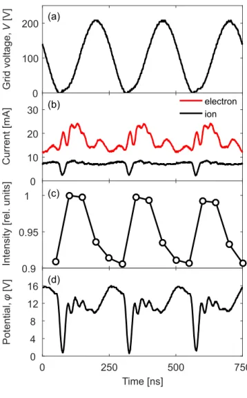
time-resolved optical emission, ion current, electron current, and beam potential. As shown
in Figure 4(a), the voltage applied across the extraction grids reaches V = 0 V once per rf
cycle. This corresponds to the sheath collapse at Grid 1 and the propagation of electrons in
the positive z-direction.
0 100 200
Grid voltage,
V
[V]
0 10 20 30
Current [mA]
electron ion
0.9 0.95
1
Intensity [rel. units]
0 250 500 750
Time [ns] 0
4 8 12 16
Potential,
φ
[V]
(a)
(b)
(c)
(d)
FIG. 4. (a) Voltage applied to the extraction grids and the (b) electron and ion currents, (c)
spa-tially averaged optical emission (solid lines added for clarity), and (d) potential of the plasma
The time-resolved ion and electron currents are measured by applying a dc voltage of
-50 V and 60 V, respectively, to the beam target (located at z = 100 mm) and measuring
the voltage drop across a 10 Ω low-inductance resistor. When biased at -50 V, it is assumed
that electrons are repelled from the beam target and hence only the ion current is collected.
Alternatively, when the beam target is biased at 60 V both electrons and ions with energy
greater than 60 eV, refer Figure 2 (a), are collected and hence the ion current can be
subtracted from the total to yield the electron current. During the brief interval of sheath
collapse, an increase in the electron current and decrease in the ion current is observed as
shown in Figure4(b). As distinct from the ion current, which exhibits one clear modulation
during each rf period, additional modulations are observed in the electron current within
the decay envelope.
It is expected that the periodic modulations in optical emission shown in Figure 4(c) are
driven by the direct-impact excitation of the Ar(2p1) energy level. Here, it is important to
note that the temporal position of the spatially averaged optical emission has been adjusted
in post-processing to align with the interval of sheath collapse at Grid 1. The observed
modulations in the optical emission are consistent with the measurements of electron current
shown in Figure 4 (b), although the decay time for the optical emission is larger. While
it is reasonable to suggest that the higher-frequency modulations observed in the electron
current could potentially be mirrored in the excitation rate, it is not possible to extract this
information due to the limited temporal resolution of the current experimental setup. The
relatively weak modulation of the temporally resolved optical emission is consistent with the
elongation of the effective lifetime due to cascade processes populating the Ar(2p5) level, as
discussed earlier.
The temporal variation of lower-energy species, e.g. in the background plasma
down-stream of the source exit, is included in the measurements of time-resolved ion current,
elec-tron current and beam potential. It is therefore reasonable to suggest that their response
to the propagation of relatively energetic ions and electrons during the sheath collapse at
Grid 1 can be responsible for the additional modulations observed, e.g. electron current
Figure4(b), after the Grid 1 sheath re-forms. Further work to limit the influence of
exper-imental boundary conditions, including the pumping rate and location of the propagation
chamber wall, is ongoing to understand these mechanisms in greater detail.
is observed to rapidly decrease from 16 V to 1 V at the same time as the grid voltage
approaches 0 V and the sheath at Grid 1 collapses. This is closely correlated with the
onset of modulations in the electron current (increase), ion current (decrease) and spatially
averaged optical emission (increase). Each minima in the beam potential corresponds to a
brief interval when the sheath at Grid 1 collapses and electrons propagate from the source.
Subsequently, forV >0 V the sheath re-forms, effectively stopping the flux of these electrons
and increasing the beam potential due to the relative increase in positive ion flux.
In conclusion, phase-resolved optical emission spectroscopy has been applied in
combi-nation with electrical measurements (ion and electron energy distribution functions, ion
and electron currents and beam potential) to study the transient propagation of energetic
electrons in a flowing plasma generated by an rf self-bias driven plasma thruster. The
re-sults suggest that the propagation of electrons during the interval of sheath collapse at the
extraction grids acts to compensate space-charge in the plasma beam.
The authors wish to thank T. Lafleur and T. Gans for useful discussions and the
York-Paris CIRC for financial assistance. This work has been done within the LABEX Plas@Par
project, and received financial state aid managed by the “Agence Nationale de la Recherche”,
as part of the “Programme d’Investissements d’Avenir” under the reference
ANR-11-IDEX-0004-02. It was also supported by a Marie Curie International Incoming Fellowship within
the 7th
European Community Framework (NEPTUNE PIIF-GA-2012-326054).
[1] D. L. Meier, S. Koide, and Y. Uchida, Science291, 84 (2001).
[2] A. V. Ivlev, S. A. Khrapak, S. K. Zhdanov, G. E. Morfill, and G. Joyce,Phys. Rev. Lett. 92
(2004).
[3] A. Fruchtman,Phys. Rev. Lett.96 (2006).
[4] P. H. Diamond, S.-I. Itoh, K. Itoh, and T. S. Hahm,Plasma Phys. Control. Fusion 47, R35
(2005).
[5] K. Ida and J. E. Rice,Nucl. Fusion 54, 045001 (2014).
[6] C. Charles and R. Boswell,Appl. Phys. Lett.82, 1356 (2003).
[7] L. Garrigues and P. Coche, Plasma Phys. Control. Fusion53, 124011 (2011).
[9] D. M. Goebel and I. Katz,Fundamentals of Electric Propulsion (Hoboken, USA: Wiley, 2008).
[10] C. Charles,J. Phys. D: Appl. Phys. 42, 163001 (2009).
[11] D. Rafalskyi and A. Aanesland, Plasma Sources Sci. Technol.25, 043001 (2016).
[12] D. Rafalskyi and A. Aanesland, J. Phys. D: Appl. Phys. 47, 495203 (2014).
[13] D. Rafalskyi and A. Aanesland, Phys. Plasmas 22, 063502 (2015).
[14] T. Lafleur, D. Rafalskyi, and A. Aanesland,Plasma Sources Sci. Technol.24, 015005 (2015).
[15] A. Greig, C. Charles, and R. W. Boswell, Front. Phys.3 (2015).
[16] C. L. Ellison, Y. Raitses, and N. J. Fisch,Phys. Plasmas 19, 013503 (2012).
[17] W. A. Hargus and M. A. Cappelli,Applied Physics B72, 961 (2001).
[18] J. Schulze, E. Sch¨ungel, Z. Donk´o, D. Luggenh¨olscher, and U. Czarnetzki,Journal of Physics
D: Applied Physics 43, 124016 (2010).
[19] T. Gans, D. O’Connell, V. Schulz-von der Gathen, and J. Waskoenig,Plasma Sources Science
and Technology 19, 034010 (2010).
[20] G. de Rosny, E. R. Mosburg Jr, J. R. Abelson, G. Devaud, and R. C. Kerns, Journal of
Applied Physics 54, 2272 (1983).
[21] F. Tochikubo, A. Suzuki, S. Kakuta, Y. Terazono, and T. Makabe,Journal of Applied Physics
68, 5532 (1990).
[22] C. M. O. Mahony, R. Al Wazzan, and W. G. Graham,Applied physics letters71, 608 (1997).
[23] T. Gans, J. Schulze, D. O’Connell, U. Czarnetzki, R. Faulkner, A. R. Ellingboe, and M. M.
Turner, Applied Physics Letters 89, 261502 (2006).
[24] D. O’Connell, T. Gans, D. Vender, U. Czarnetzki, and R. Boswell, Physics of Plasmas 14,
034505 (2007).
[25] K. Dittmann, D. Drozdov, B. Krames, and J. Meichsner, Journal of Physics D: Applied
Physics 40, 6593 (2007).
[26] D. W. Liu, F. Iza, and M. G. Kong, Applied Physics Letters 93, 261503 (2008).
[27] V. Schulz-von der Gathen, L. Schaper, N. Knake, S. Reuter, K. Niemi, T. Gans, and J. Winter,
Journal of Physics D: Applied Physics41, 194004 (2008).
[28] K. Niemi, S. Reuter, L. M. Graham, J. Waskoenig, N. Knake, V. Schulz-von der Gathen, and
T. Gans, Journal of Physics D: Applied Physics43, 124006 (2010).
[29] J. E. Chilton, J. B. Boffard, R. S. Schappe, and C. C. Lin, Phys. Rev. A57, 267 (1998).
Pro-cessing, 2nd ed. (Wiley, New Jersey, 2005).
[31] J. Schulze, Z. Donk´o, B. G. Heil, D. Luggenh¨olscher, T. Mussenbrock, R. P. Brinkmann, and
U. Czarnetzki, Journal of Physics D: Applied Physics41, 105214 (2008).