This is a repository copy of
Self-adaptive approach for optimisation of passive control
systems for seismic resistant buildings
.
White Rose Research Online URL for this paper:
http://eprints.whiterose.ac.uk/132421/
Version: Accepted Version
Article:
Eljajeh, Y. and Petkovski, M. orcid.org/0000-0002-3788-0772 (2018) Self-adaptive
approach for optimisation of passive control systems for seismic resistant buildings.
Bulletin of Earthquake Engineering, 16 (7). pp. 3171-3194. ISSN 1570-761X
https://doi.org/10.1007/s10518-018-0309-9
© 2018 Springer Science+Business Media B.V., part of Springer Nature. This is an author
produced version of a paper subsequently published in Bulletin of Earthquake
Engineering. Uploaded in accordance with the publisher's self-archiving policy.
[email protected] https://eprints.whiterose.ac.uk/
Reuse
Items deposited in White Rose Research Online are protected by copyright, with all rights reserved unless indicated otherwise. They may be downloaded and/or printed for private study, or other acts as permitted by national copyright laws. The publisher or other rights holders may allow further reproduction and re-use of the full text version. This is indicated by the licence information on the White Rose Research Online record for the item.
Takedown
If you consider content in White Rose Research Online to be in breach of UK law, please notify us by
Self-adaptive approach for optimisation of passive control systems for seismic
resistant buildings
Yasser Eljajeh* and Mihail Petkovski**
* Curtins Consulting LTD, 17-19 Whitworth Street, Manchester, UK, M20 3ES, [email protected]
** University of Sheffield, Department of Civil and Structural Engineering, Sir Frederick Mappin
Building, Sheffield, UK, S1 3JD. [email protected]
Keywords:
Seismic optimisation, Semi-active control, Passive control, Post-tensioned steel structures, Friction slip force
Abstract
The concept of passive control of the seismic response of structures was introduced to improve the performance of structures by increasing their energy dissipation and reduce or eliminate damage in the structural elements. The key task in the design of passive systems is to determine the forces in the control devices (yield/slip or post-tensioning) at each floor, that will result in best performance (e.g. minimum inter-storey drift). This can be achieved by large parametric studies in which both the maximum control force (e.g. at ground level) and the distribution of forces along the height of the structure are varied. Alternatively, optimum forces in the devices can be achieved by semi-active control, where the structure self-adapts to the earthquake. Both solutions are expensive: the first requires hundreds of non-linear response simulations in the design stage; the second needs a system of sensors, controllers and electromechanical devices. Presented here is a new Self-Adaptive
Optimisation Approach (SAOA) in which the self-optimisation of a semi-active system is used in the design stage and the resulting distribution of control forces is adopted as a passive system. The new approach was evaluated through comparing the simulated dynamic responses of two relatively simple benchmark structures (braced and post-tensioned) with three sets of control forces: (i) passive system with forces obtained in parametric study, (ii) semi-active system with self-adapting control forces, and (iii) passive system with SAOA-optimized forces. The results show good
performance of the SAOA systems, indicating that SAOA offers a simple and effective solution that can replace the existing optimisation approaches for the design of passively controlled earthquake
resistant structures.This study presents a novel idea of using the semi-active control as a tool for
optimising a passive control system. The passive control systems can be further improved by a larger study in which the semi-active control algorithms are also optimised.
1.
Introduction
two major advantages of passive control systems based on distributed friction/yield elements. First, they remove a significant part (or all) of the energy dissipation and stiffness alteration functions from the main structural members, reducing or avoiding damage in the main structure. Second, the friction slip load and stiffness of the control elements can be set independently, which allows for optimisation of their performance.
[image:3.595.72.382.338.495.2]Passive control systems for seismic resistance vary in the way they behave or dissipate the input energy. Some of them dissipate energy through friction (Grigorian et al. 1993; Levy et al. 2000; Lee et al. 2008), while other systems utilise yielding of specially designed elements as a means of energy dissipation (Moreschi, 2000; Moreschi and Singh, 2003; Kammouh et al. 2017). Some of these elements were also integrated in post-tensioned (PT) steel beam-column connections so they provide energy dissipation capacity in addition to the self-centring ability that characterises the post-tensioned connections (Figure 1). The energy dissipation element added to the post-post-tensioned connections can be friction-based (Rojas et al. 2004; Rojas et al. 2005; Tsai et al. 2008; Kim and Christopoulos, 2008), or yield based. The yield based elements added to the PT connections take various shapes such as: (a) top and seat angles (Garlock et al. 2007; Garlock and Li, 2008), (b) yielding bars (Ricles et al. 2001; Christopoulos et al. 2002a) and (c) Web Hourglass Shape Energy (Vasdravellis et al. 2013a).
Figure 1: Hysteretic model of post-tensioned connection with energy dissipating bars (Christopoulos et al. 2002a): (a) post-tensioned strands, (b) energy dissipating bars and (c) post-tensioned connection (Eljajeh, 2013).
The design of passive control systems can be done by (i) designing the base structure (e.g. as a moment resisting frame) and then (ii) adding a control system, such as braces and yield/friction connections, or post-tensioned (PT) beam-column connections; and determining the control forces (yield/slip loads or PT forces) for each storey (Tsuji and Nakamura, 1996; Fu and Cherry,1999; Fu and Cherry,2000). The control forces can be scaled to some characteristics of the base frame (strength, stiffness, mass). For example, Moreschi and Singh (2003) suggested that for a frame equipped with
braces and friction connections, the slip force in the connection Ps at any storey could be calculated
as a proportion of the storey yield shear force Py (Equation 1).
Ps=SR * Py= SR * y * ks (1)
where SR is the ratio between the stiffness of braces kb and the storey stiffness ks; and y is storey
The larger SR would result in activation of the friction damper at smaller storey deformations, which
would increase the energy dissipation for any given level of slip force (i.e. any value of ).
The design problem is reduced to finding the values of that would produce the best response:
minimise storey drifts, without increasing the storey shear, which usually coincide with the values that maximise the energy dissipation in the friction connections. For small values of (e.g. < 0.3) the response would be similar to that of a frame, with small additional energy dissipation in the connections at both small inter-storey drifts (within the elastic range) and larger deformations, where the bulk of energy would be dissipated by the plastic hinges in the frame. On the other hand, for large values of (e.g. > 0.7) the response would be close to that of a braced frame,
characterised by small deformations, but large axial forces in the braces and adjacent columns, and with connections activated only occasionally, during the largest earthquake cycles, which would result in low energy dissipation. Additional drawback of large slip forces is that, in case of asymmetric earthquake reversals, the connections may lock and keep the structure tilted to one
side. Hence, the optimum performance could be expected within the range of =0.3-0.7. For a
single storey, Mualla and Belev (2002) suggested that *SR= 0.1 - 0.4 to minimize deformations and
storey shear and maximize the dissipated energy.
In properly designed multi-storey buildings, for earthquakes in which the first mode dominates the
response, the storey strength Py would taper with the height, and consequently, a constant ratio
would produce a trapezoidal distribution of control (slip/yield) forces {Ps,i}. If the structure is not
properly designed (e.g. in cases of retrofit of existing buildings), then better results would be
achieved by following the seismic demand, rather than the distribution of capacities along the height of the building. This can be achieved by assuming a trapezoidal distribution along the height, finding the optimum control force for the first storey (Ps,1= Py,1), and the optimum ratio between the
control forces at the top and the first storey (=Ps,n/Ps,1). Researchers who have investigated these
two parameters found that optimum performance was generally achieved by assuming 1=0.4-0.6
for the first storey, and a trapezoidal distribution, with =0.3-0.6 (Kelly et al. 1988; Daniel et al. 2012).
If the structure-earthquake combination produces a response in which higher modes have significant influence, the optimum distribution of control forces along the height of the structure could be found by using complex genetic algorithms (Apostolakis and Dargush ,2009; Moreschi and Singh ,2003).
Simulations of several recorded earthquakes and buildings at different fundamental frequencies showed significant differences in performance (e.g. maximum inter-storey drift, or base shear) within this range (Foti et al. 1998; Vulcano and Mazza, 2000). The results of previous studies however demonstrate that the performance of a particular building under a limited set of earthquakes can be significantly improved by narrowing the range of slip/yield forces at the base and their distribution along the height (Moreschi, 2000). This optimisation procedure requires a large and detailed parametric study which would be too expensive for the design of ordinary buildings. Research studies of automated optimisation are usually limited to the use of over-simplified structural models (Gluck et al. 1996; Xu et al. 2003; Soong and Cimellaro 2009), which do not satisfy the requirements of design codes such as (Eurocode 8, 2004).
One solution for optimised distribution of control forces is semi-active control, in which control forces change (within the wider limits of the optimum performance range) during the earthquake,
depending on the current state of the response. In other words, the structure finds the best
that the best performance of several semi-actively controlled structures was within the optimum
performance range (bound by low and high control forces) for each of the wide range of
earthquakes, which was previously determined through parametric studies of passively controlled structures. This self-adaptability also reduces the risk of an unforeseen earthquake, i.e. an excitation with frequency content and time history envelope that were unforeseen during the design. Despite the advantages of semi-active control, this approach is still viewed with reserve due to concerns about cost and reliability (Lane et al.1992; Makris and McMahon,1996, Dyke and Spencer 1997(a)), and is rarely considered as a design option (Nishitani and Inoue, 2001). In addition, the efficiency of semi-active control of structures has been a subject of debate. Although many previous research studies indicated that semi-active control is superior to passive control (Dyke and Spencer, 1997(b); Sadek and Mohraz, 1998), a research work carried out by Chae et al. (2013) showed that this superiority can be proved only when a limited number of earthquakes is used in the structural simulations. This was confirmed by the previous work of the authors (Eljajeh, 2013) showing that when a large number of earthquakes was used, the performance of the semi-active control was similar to that of passive systems.
In the procedure presented here the friction forces for a passive system are obtained by a simulation of semi-active control of the same structure using an artificial earthquake, generated to match the design spectrum. The idea of using the self-optimisation of a semi-active system came from an observation that the semi-active control simulations with one structure, under a large set of different earthquakes, resulted in a relatively narrow range of control force distributions (Eljajeh, 2013), and that these distributions were very different from the generally assumed trapezoidal distributions.
The presented research introduces a new, reliable and self-adaptive optimisation methodology that results in optimum distribution of passive control forces in earthquake resistant buildings. This optimisation approach utilises the efficiency of semi-active control by analysing the performance of these systems in the design stage, and the simplicity and reliability of passively controlled structures. The distinction of the proposed methodology is that it sets up the control forces from the storey stiffness demand, as the response of the structure is ultimately controlled by its stiffness, which varies during the earthquake as a result of activation/deactivation of both the friction connections and plastic hinges in the frame members.
The outline of this paper is organised as follows: (i) the research hypothesis is presented; (ii) a step-by-step procedure for the new Self Adaptive Optimisation Approach (SAOA) is described; (iii) the details of the two prototype structures and the seismic excitations used for assessment of the SAOA performance are given, (iv) results of the simulations of dynamic response of the two structures are presented, (v) a discussion of the results is presented, and finally (vi) the conclusions of this study are presented.
2.
Research hypothesis
A semi-active control system changes specific characteristics of the structure based on its response and in accordance with the control algorithm at predefined time intervals (Nishitani et al. 2003). The
proposed optimisation approach uses these changes to determine the optimum values for the
control forces in a corresponding passively controlled structure.
(Hajirasouliha et al. 2012) (Uniform Drift Distribution algorithm UDDA, Eljajeh and Petkovski, 2015). The results showed that the structure had the same shape of the control (in this case
post-tensioning) forces distribution at the end of any simulation under different ground excitations.
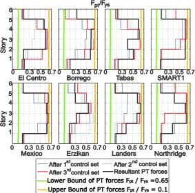
Furthermore, Eljajeh (2013) found that the shape of the PT force distribution obtained in the first
[image:6.595.72.356.189.469.2]change in forces (1st control set) changed very little during the remaining time of the simulation
(Figure 2). The aim of this study was to find out if the semi-active UDDA control would produce the same behaviour for other, different types of structures.
Figure 2. Development of PT forces in UDDA-controlled frame (Eljajeh, 2013).
If this is true, then the Self Adaptive Optimisation Approach (SAOA) can be used for design of passively controlled earthquake resistant structures, which can be used to determine the optimal values for the passive control forces based on the self-adaptability provided by the considered semi-active control system. This may also motivate further research in improvements of the UDDA and other semi-active control systems, which would lead to improved SAOA methodologies.
3.
A step-by-step optimisation procedure
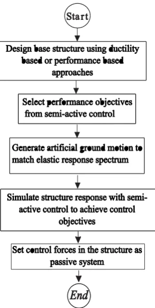
In this section is presented a detailed methodology for using the SAOA to determine the optimum values of control forces in any part of an earthquake resistant structure. The methodology includes the following steps:
• Step 1
• Step 2
Select performance objectives, which need to be achieved by the semi-active control system. These would include limits in curvature ductility demand in plastic hinges or axial loads in columns for a given ductility class in Eurocode 8 (2004), or maximum inter-storey drifts for a given performance level by ASCE41 (2013) and FEMA445 (2006).
• Step 3
Generate an artificial design ground motion scaled to match the design response spectrum in Eurocode 8 (2004), or the response spectrum of the design based earthquake in ASCE41 (2013) and FEMA445 (2006).
• Step 4
Simulate the dynamic response of the structure equipped with a semi-active control system and determine the control force (slip/yield, PT) distribution. During the earthquake excitation and due to control actions, different changes will be applied to control forces. The control forces are applied using the Uniform Drift Distribution Algorithm UDDA (Eljajeh and Petkovski, 2015). The resultant values of control forces are given from:
FR= Fi + Fc (2)
where, FR is the resultant value of the control forces, Fi is the initial value of the control forces, and
Fc is the sum of all control changes applied to the initial control forces during the artificial
earthquake excitation.
This set of control forces was adopted so that it produces the forces required by the controlled structure for longer than other during the response. Other forces can also be used, such as a fixed proportion of the maximum forces at each floor; proportion of the maximum (or average) force at level 1, with some pre-set distribution along the height; or even the most used vertical force
distributions recorded in every step of the analysis. However, presented here is the concept of using semi-active control as (self) optimisation tool. Better results can be achieved by further investigation of the procedure including using different control strategies and algorithms.
Figure 3. Optimisation procedure using the Self-Adaptive Optimisation Approach (SAOA).
The optimal friction forces are obtained by SAOA through simulation of the response of the building to an artificial earthquake derived from a code-based design response spectrum. The uncertainties of the analysis and design of the structure for a specific response spectrum also apply to the control forces obtained from SAOA. This means that SAOA will not perform the same for all earthquakes matching the design spectrum. It will however, give optimal performance when considering the statistics of the structural response under large number of earthquakes.
It should be noted that this analysis does not account for any variations in friction force due to cumulative movements or change or temperature which may affect the derived friction forces by a factor of 2-3 and invalidate the obtained results (Constantinou et al.2007). Also, post-tensioning forces are subject to approximately 10 20% changes due to relaxation in the pre-stressing (Eljajeh 2013). More stable, or at least more predictable friction forces can be achieved by using automotive brake-pad material, first proposed by Pall and Marsh (1982), and recently tested by several research groups (Sano and Katsumata, 2008; Stefancu et al.2012; Qu et al. 2015), or some new synthetic materials in the friction interfaces.
4.
Structures and Seismic Inputs for Evaluation of SAOA
The performance of the Self-Adaptive Optimisation Approach (SAOA) is evaluated through
4.1.Frame Prototypes
[image:9.595.75.442.192.419.2]The first benchmark structure is a four-storey-one-bay dual steel frame with friction connections (Figure 4). The primary elements of the frame (sections of columns, beams and braces) were designed in accordance with the ductility-based design approach of Eurocode 8 (2004). All elements are class 1 (Eurocode 3, 2001) to provide sufficient post-yield rotation under severe earthquake loading. The SAOA will be used to determine the optimal passive friction slip force of the friction damper at each storey.
Figure 4. Four-storey concentric steel braced frame: (a) frame geometry and sections, (b) idealised model of the frame, (c) modal properties of the frame and (d) element and section properties.}
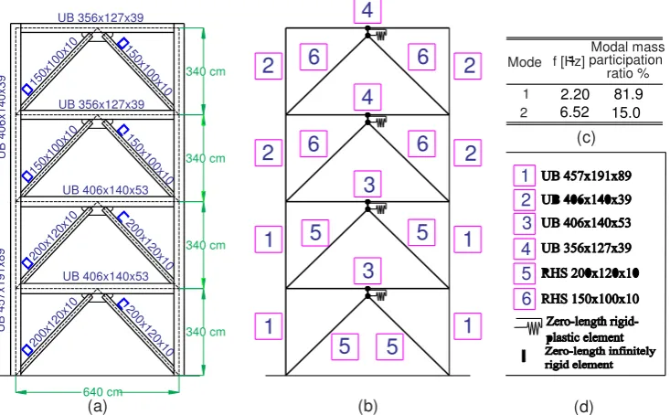
The second benchmark structure is a six-storey-one-bay post-tensioned steel frame used in a previous study by Eljajeh and Petkovski (2015) (Figure 5). The post tensioned frame was designed in
accordance with the capacity design principles specified in Eurocode 8 (2004), for ductility class DCH,
by assuming the following damage sequence (Eljajeh and Petkovski, 2015): (1) inelastic deformations in the connection (yielding/slip of dissipaters), (2) plastic hinges at the base of columns, (3) plastic deformations in beams under combined axial load and moment, (4) hinges in columns (above base) and (5) failure of connection (yielding of strands). The assumed damage hierarchy complies with that proposed by Garlock et al. (2007) and used in performance-based design (FEMA445, 2006) of post-tensioned frames. In order to achieve plastic deformations under moments and axial forces in the beams, they are assumed to be laterally restrained elements made of class 1 sections (Eurocode 3, 2001). The PT connection is represented by a single rotational spring model (Eljajeh and Petkovski, 2013). Unlike the discrete springs model (Dimopoulos et al. 2013; Tzimas et al. 2016) or the finite element model (Vasdravellis et al. 2013), the used connection model does not exactly represent the real behaviour of PT frames as it does not: (i) capture true axial force in the PT beam-column
interface, (ii) take the effect of the diaphragmatic action from slabs, iii) simulate the expansion of the frame or (iv) include the effect of column restraint on the frame expansion (Eljajeh,2013). This model however is simple to implement in a frame analysis and results in a global response of the frame similar to that obtained using multi-element discrete springs models (Dobossy et al. 2006).
The SAOA will be used to determine the initial value of the post-tensioning force used at each floor level. UB 356x127x39 150x 100x 10 15 0x 10 0x10 UB 356x127x39 Mode Modal mass f [Hz] participation
ratio % 1 150x 100x 10 15 0x10 0x 10 UB 406x140x53 (c) 2 6.52 1 2 3 4 5 6 2 1 1 2 2 2 1 1 5 5 5 5 6 6 6 6 4 4 3 3 UB 406x140x53 200x 120x 10 20 0x12 0x 10 200x 120x 10 20 0x12 0x 10 340 cm 340 cm 340 cm 640 cm 340 cm U B 4 5 7 x 1 9 1 x 8 9 U B 4 0 6 x 1 4 0 x 3 9
(a) (b) (d)
2.20 81.9
Figure 5. Six-storey PT steel braced frame: (a) frame geometry and sections, (b) idealised model of the frame, (c) modal properties of the frame and (d) element and section properties (Eljajeh and Petkovski, 2015).
Simulations of the seismic behaviour of the passively and semi-actively controlled frames were performed using FASAC-2D (Frame Analysis with Semi-Active Control; Eljajeh (2013)), a computer program developed specifically for this purpose.
4.2.Determining Control Forces using Artificial Earthquake
An artificial earthquake was generated to obtain the control forces using SeismoArtif software (Seismosoft, 2013). The artificial earthquake was generated to match Eurocode 8 (2004) response spectrum for soil class A with peak ground acceleration PGA=0.45g (Figure 6-a). The earthquake, generated for near-field with 6.5 magnitude, has 30 sec duration, 0.459g PGA and a 15.5 sec significant duration (Figure 6-b).
Figure 6. Details of the artificial design earthquake: (a) response spectra and (b) time history (Seismosoft, 2013).
Mode
Modal mass participation ratio %
1 0.52
(c)
2 f [Hz]
(d)
[image:10.595.72.403.540.741.2]The dynamic responses of the braced and post-tensioned frames were simulated using the artificial earthquake in order to determine the distribution of friction slip and post-tensioning forces. The simulations were carried out with semi-actively varying friction and post-tensioning forces using the control law proposed by Eljajeh and Petkovski (2015) for Uniform Drift Distribution (UDD). The resultant forces from the simulations using Equation 2 are given in Table 1.
Control Force 1st Storey 2nd Storey 3rd Storey 4th Floor 5th Storey 6th Storey
Friction Force [kN] 520.3 578.9 463.4 201.5 --
PT Force [kN] 222.6 536.3 539.0 536.3 372.8 178.4
Table 1. Resultant forces from simulations of the dynamic response of semi-actively controlled structures to the artificial design earthquake for braced frame with controlled friction connections and PT frame with controlled PT forces.
4.3.Earthquake Records
A set of 10 recorded earthquakes was used to simulate the dynamic response. Other researchers (Karavasilis and Seo, 2011; Dimopoulos et al. 2016) have used a larger number of earthquakes. The reason for using a smaller set is that this paper presents a novel approach in designing a passive control system, rather than a detailed study for optimisation of the semi-active control algorithms. The earthquakes were chosen to represent motions with different characteristics such as frequency content and time history envelope (number and sequence of major acceleration reversals) in order to illustrate the procedure. Adding further earthquakes may change the resulting passive system, although if their characteristics are similar to some of the 10 records, the statistics of the response parameters should not be significantly affected.
Details of the earthquake records are presented in Table 2. All seismic motions are scaled to match the target design response spectrum as described by NEHRP (2011). The response spectra of the earthquake records are shown along with the Target Design Spectrum (PGA=0.45g, Soil class A (Eurocode 8, 2004)) in Figure 7.
Earthquake Year Country Record t (sec) Duration
(sec)
PGA [g]
Cape Mendocino
1992 USA CAPEMEND/PET000 0.020 36.000 0.59
Imperial Valley
1979 USA IMPVALL/H-BCR140 0.005 37.625 0.59
San Frenando
1971 USA SFERN/PCDDWN 0.001 41.640 0.70
Superstin Hills
1978 USA SUPERST/B-SUP045 0.010 22.250 0.68
Kobe 1995 Japan KOBE/NIS000 0.010 40.960 0.51
Loma Prieta
1989 USA LOMAP/G01090 0.005 39.950 0.47
Gazli 1976 Turkey GAZLI/GAZ000 0.005 16.275 0.61
Northridge 1994 USA NORTHR/MU2035 0.01 23.980 0.62
N.Palm Springs
1986 USA PALMSPR/WWT180 0.005 20.050 0.49
[image:11.595.75.524.467.717.2]Duzce 1999 Turkey DUZCE/DZC270 0.005 25.900 0.54
Figure 7. Response spectra of 10 recorded ground motions and target design response spectrum.
5.
Results of Simulations
Results of the simulations of dynamic response of the braced and post-tensioned frames are
presented for the ten earthquake records in terms of: (a) the mean value , (b) the mean plus
standard deviation + and (c) the mean minus standard deviation - . Values of interest are:
• frame displacements,
• inter-storey drifts,
• accelerations, and
• base shear.
The dynamic response of each frame was compared for:
a. control forces varied by using semi-active control, and
b. control forces optimised by using SAOA.
Dynamic response of frames with lowest and highest values of passive control forces are shown as references for nearly bare moment frame (when using lowest passive control forces) and nearly locked frame (when using highest passive control forces).
The lowest and highest values of the passive control forces were assumed as:
• Braced frame: low/high forces were chosen to represent two limit cases: nearly bare frame and
nearly braced (locked) frame.
• PT Frame: low/high PT forces are 80 kN (taken from the full centring requirement for the PT
connections (Christopoulos et al. 2002) and 70% of the yield force of the strands and using a rectangular distribution.
5.1.Results of the Braced Frame
Figure 8. Statistics of maximum storey displacements of the braced frame: (a) , (b) - and (c) +.
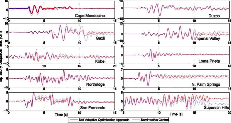
In Figure 9 are shown 15 seconds of the time histories of the top storey displacements from each of the ten earthquake records. It can be seen that in most cases the frame with control forces
optimised using SAOA outperforms or show similar performance to frame with semi-active control.
Figure 9. Time histories of braced frame top storey displacements.
While not normally part of the performance assessment, it is important to check whether SAOA satisfied the objective of the control law which was used in the semi-active control: the uniform distribution of inter-storey along the height of the building. This can be used as an additional
performance criterion, as it indicates that all stories contribute equally to the energy dissipation and that there is no force concentration in one part of the building. The statistical values for the
maximum inter-storey drifts in the ten earthquake records (Figure 10) show a more uniform drift distribution in the SAOA than any of the other structures (including the semi-actively controlled frame). In the other three structures the top storey experienced significantly lower maximum drifts than the lower three stories, hence participating less to the energy dissipation in the structure.
0 5 10 15 20
1 2 3
4 (a)
Displacement [cm]
S
to
ry
0 2 4 6 8 10
(b)
Displacement [cm]
0 5 10 15 20 25
(c)
Displacement [cm]
[image:13.595.74.468.293.503.2]Figure 10. Statistics of maximum inter-storey drift of the braced frame: (a) (b) and (c) .
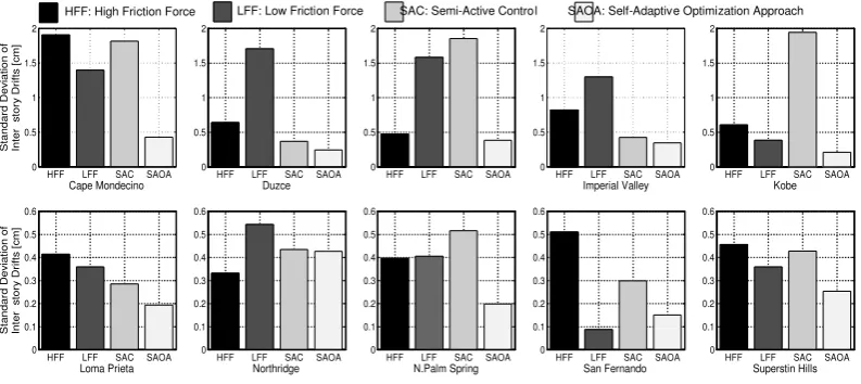
This can be even better illustrated by the values of the standard deviation between the maximum inter-storey drifts in each storey (Figure 11) in the 10 recorded earthquakes. The results show that the SAOA frame has the most consistent behaviour in terms of achieving uniform inter-storey drifts, with minimum deviation in 8 of the 10 earthquakes, and never resulting in the maximum deviation (which was obtained for different frames under different earthquakes).
Figure 11. Standard deviations of inter-storey drifts of the braced frame.
The storey displacements alone are only part of the performance assessment, and accelerations, inter-storey drifts and base shear also need to be considered.
Floor accelerations are an important performance criterion as damages of non-structural elements are usually associated with floor accelerations rather than floor displacements (Karavasilis and Seo, 2011). The statistics of maximum floor accelerations are shown in Figure 12.
1 2 3 4 5
1 2 3 4
0 1 2 3 0 2 4 6 8
HFF LFF SAC SAOA 0 0.5 1 1.5 2 S ta n d a rd D e v ia ti o n o f In te r s to ry D ri ft s [ c m ] Cape Mondecino
HFF LFF SAC SAOA 0 0.5 1 1.5 2 Duzce
HFF LFF SAC SAOA 0
0.5 1 1.5 2
HFF LFF SAC SAOA 0 0.5 1 1.5 2 Imperial Valley
HFF LFF SAC SAOA 0 0.5 1 1.5 2 Kobe
HFF LFF SAC SAOA 0 0.1 0.2 0.3 0.4 0.5 0.6 S ta n d a rd D e v ia ti o n o f In te r s to ry D ri ft s [ c m ]
Loma Prieta HFF LFF SAC SAOA
0 0.1 0.2 0.3 0.4 0.5 0.6
Northridge HFF LFF SAC SAOA
0 0.1 0.2 0.3 0.4 0.5 0.6
N.Palm Spring HFF LFF SAC SAOA
0 0.1 0.2 0.3 0.4 0.5 0.6
San Fernando HFF LFF SAC SAOA
[image:14.595.72.469.339.516.2]Figure 12. Statistics of maximum floor accelerations of the braced frame: (a) (b) and (c) .
Figure 12 shows that the frame designed using SAOA experiences the lowest levels of maximum floor acceleration. Floor accelerations obtained by using the new optimisation approach are similar to those obtained by using semi-active control and lower than those in the frame with low friction forces and much lower than the passive frame with high friction forces. The first 15 seconds of the top floor acceleration time histories (Figure 13) show similar acceleration levels for SAOA with the for the braced frame with Semi-Active (SA) control.
Figure 13. Time histories of braced frame top floor accelerations.
Figure 14. Statistics of maximum base shear of the braced frame: (a) (b) and (c) .
Maximum base shear for the ten earthquake records (Figure 15) also shows that in all cases the SAOA resulted in the values close to the semi-active and low-force passive frames, and always lower than the those in the high-force passive frame.
Figure 15. Maximum base shear resulted from the ten earthquake ground motions in the braced frame.
This type of response, in which a passively controlled structure experiences deformations close to a braced frame (or in this case high-force passive frame) but at the same time develops force demands as low as those in the moment resisting frame (or low-force passive), is characteristic for passive frames with optimum friction force distribution. The results of this analysis show that the SAOA produced an optimum (or near-optimum) passive force distribution without the need for a large parametric study. What is even more important is that the vertical distribution of control forces resulting from SAOA is far from the usually assumed trapezoidal distribution, which means that it is possible that this configuration would have been missed in a usual parametric study; and perhaps achieved only by the means of a much larger and more complex multi-parameter optimisation analysis. Moreover, the performance of the SAOA frame was as good as (or even better) than that achieved by semi-active control, without the need for an expensive and potentially unreliable control system.
5.2.Results for the Post-Tensioned (PT) Frame
In Figure 16 are shown the statistics of the maximum top floor displacements obtained in simulations of the dynamic response of four PT frames (one under semi-active control, the other
LFF HFF SAC SAOA
0 200 400 600 800 (a) B a s e S h e a r [k N ]
LFF HFF SAC
(b) LFF HFF SAC(c)
LFF: Low Friction Force, HFF: High Force Force, SAC: Semi Active Control, SAOA: Self-Adaptive Optimization Approach
SAOA SAOA
HFF LFF SAC SAOA 0 200 400 600 800 Cape Mendocino M a x im u m B a s e S h e a r [k N ]
HFF LFF SAC SAOA Duzce
HFF LFF SAC SAOA Gazli
HFF LFF SAC SAOA Kobe
HFF LFF SAC SAOA 0 200 400 600 Loma Prieta M a x im u m B a s e S h e a r [k N ]
HFF LFF SAC SAOA Northridge
HFF LFF SAC SAOA San Fernando
HFF LFF SAC SAOA Superstin Hills HFF LFF SAC SAOA
Imperial Valley
HFF LFF SAC SAOA N. P m Springsal SAC: Semi-Active Control
[image:16.595.72.471.296.503.2]three passive, using low-level, high-level and SAOA-determined PT forces) to ten earthquake records. The lowest maximum values were obtained by using the high initial PT forces in all stories. The second lowest displacements were achieved by using SAOA to determine the initial PT forces. The average of top storey displacements achieved by using SAOA was 26.8 cm, or 12.5% less than the average of maximum top storey displacements achieved by the semi-active control, and 17.1% less than the average of maximum top storey displacements achieved when using low initial post-tensioning force (FptLow=300 kN).
Figure 16. Statistics of maximum storey displacements of the post-tensioned frame: (a) (b) and (c) .
The time histories of the first 15 seconds of top storey displacements under each earthquake excitation (Figure 17) show SAOA frame displacements similar to those obtained using high PT forces, and similar or slightly lower than those produced by the semi-active control. In two cases (Imperial Valley and N. Palm Springs) SAOA results significantly lower displacements than the active control. A closer inspection of the responses to these two records shows that after the semi-active control was activated (introducing higher PT forces) the peak-to-peak displacements were kept at a similar level with those in the high-forces passive and SAOA frames, but the frame vibrated out of its vertical axis, leaning to one side (shown as positive direction in Figure 17), and resulting in much higher overall deformations. In these two earthquakes, the initial tilt of the structure was avoided in the SAOA frame in which the semi-active forces were applied as initial PT forces. In one case (San Fernando) the semi-active control achieved a significant reduction in displacements by introducing higher PT forces much later in the response. When this force distribution was used as an initial set of PT forces in the SAOA frame, the increased structural stiffness resulted in higher
response, similar to that in the high-force passive system. This however is a single case which shows the high efficiency of semi-active control for certain structure-earthquake combinations. In a general
case however, the statistics of the maximum storey displacements (i.e. , and ) show that
the performance of a SAOA PT frame is as good as or better than the semi-active active structure.
0 7 14 21 28 35
1 2 3 4 5 6
Displacement [cm]
S
to
ry
0 4 8 12 16 20
Displacement [cm] 0 10Displacement [cm]20 30 40 50
Low PT force High PT force Semi active control SAOA
Figure17. Time histories of post-tensioned frame top storey displacements
[image:18.595.74.525.71.275.2]The SAOA PT frame does not show a significant improvement in terms of maximum inter-storey drifts (or shear forces) but the inter-storey drifts obtained using SAOA are more uniform than those obtained in all other cases (Figure 18).
Figure 18. Statistics of maximum inter-storey drifts of the post-tensioned frame: (a) (b) and (c) .
The standard deviations of inter-storey drifts of the post-tensioned frame (Figure 19) also show that SAOA is less efficient when applied to PT frames that than in the case of braced frame (so is the efficiency of the semi-active control). The reason for this is that in PT frames the stiffness of the moment-resistant frame can only be reduced by reducing the high level of PT forces; whereas in the braced frame it can be varied in a wide range between a moment resisting frame (low-force passive) and fully braced frame (high-force passive).
0 3 6 9
1 2 3 4 5 6
(a)
Inter storey drift [cm]
S
to
re
y
0 2 4 6
(b)
Inter storey drift [cm]
0 4 8 12
(c)
Inter storey drift [cm]
Figure19. Standard deviation of inter-storey drifts of the post-tensioned frame.
[image:19.595.73.471.70.257.2]The averages of maximum floor acceleration (Figure 20) and base shear (Figure 21) of the PT frame do not vary significantly for different cases, with the difference between maximum base shear obtained by using low PT forces (worst case) and semi-active control (best case) less than 7%.
Figure 20. Statistics of maximum floor accelerations of the post-tensioned frame: (a) (b) and (c) .
Figure 21. Statistics of maximum base shear of the post-tensioned frame: (a) (b) and (c) .
6.
Discussion
Results of SAOA braced frame can be compared to results of previous research of semi-active control of braced frames. The results of SAOA are similar to those obtained by Ozbulut et al. (2011) using
0.4 0.6 0.8 1
1 2 3 4 5
6 (a)
Acceleration [g]
S
to
ry
0.3 0.5 0.7 0.9
(b)
Acceleration [g] 0.5 0.7 0.9 1.1 1.3 (c)
Acceleration [g]
Low PT force High PT force Semi active control SAOA
LPT HPT SAC SAOA 0
200 400 600 800
(a)
B
a
se
S
h
e
a
r
[k
N
]
LPT HPT SAC SAOA
(b) LPT HPT SAC SAOA(c)
[image:19.595.74.427.340.522.2]adaptive friction damper. The performance of frame with friction forces optimised by using SAOA is also comparable to that of controlled stiffness devices and friction dampers (Ribakov, 2004) applied on dual frames. Furthermore, the self-adaptive optimization approach seems to outperform the semi-active control for undamaged structures (Bitaraf et al. 2012).
The SAOA can be used to optimize control forces in structures subjected to high non-linearity under seismic loading as the design base structure acts as passive system. On the other hand, most of the previous research work on semi-active control systems is limited to linear systems (Eljajeh and Petkovski, 2015) using Lyapunov stability (Leitmann, 1994) or quadratic regulators (Sadek and Mohraz, 1998; Dyke et al. 1996; Dyke and Spencer, 1997b). Semi-active control based on the fuzzy logic can be applied to non-linear structures (Zhou et al. 2002), but due to the system complexities (Zhou et al. 2002, Bitaraf et al. 2010), this type of control has only been used on simplified structures with maximum two dampers (Bhardwaj et al. 2006).
The results of frame structures with control forces optimized by using SAOA are therefore assessed by comparing their dynamic response with the response of passive structures with conventional distributions of control forces or semi-actively controlled structures.
The statistics of the braced frame maximum displacements under 10 earthquake records (Figure 7) show that displacements from SAOA are lower than those obtained by using semi-active control. The reason is that the goal of the semi-active UDDA controller is to equalise the inter-storey drifts, which would allow activation of friction connections in all storeys and ultimately increase the energy dissipation. At the end of each control interval the controller is programmed to react to the current state of the structure, but it cannot predict the seismic input in the next interval. This means that, in some cases, it changes from a better to a worse force distribution, and then, in the next interval, when it detects increased deformations, it reverts back towards the better distribution, but the structure has already undergone a large (potentially maximum) deformation reversal. In other words, the system maintains the optimum control force distribution during most of the time history, but this distribution is not continuous. In the SAOA, the results of the simulation show this
predominant distribution, which is then applied as constant through the whole earthquake.
Moreover, SAOA allows for finding the statistical measure of the predominant distribution for a wide range of earthquakes, and ensures that the system will perform well in all cases. These results are in agreement with the conclusion drawn by Chae et al. (2013) who found that semi-active control offers minimal or no advantage over passive control when using large number of earthquakes to simulate the dynamic response of structures. This result is also confirmed from the maximum storey displacements of the PT Frame (Figure 15).
Frame Design Case
Storey
1st 2nd 3rd 4th 5th 6th
PT Frame LPT 9.1% 10.6% 17.5% 22.6% 22.5% 17.1%
HPT -12.2% -12.6% -10.3% -8.4% -8.3% -14.1%
SAC 4.4% 6.5% 7.2% 11.4% 10.3% 12.5%
Braced Frame
LFF 126.1% 112.1% 112.9% 104.7%
---
HFF 2.5% 3.1% 1.4% -5.3%
[image:21.595.75.524.72.183.2]SAC 43.0% 45.5% 24.8% 16.0%
Table 3. Percentage reductions and increase of average maximum storey displacements from frames designed using SAOA: (+) increase, (-) reduction.
Table 3 also shows that the maximum displacements of the PT frame with SAOA post-tensioning forces are higher than those obtained from the passive PT frame using high PT force. The low inter-storey drifts and displacements of the PT frame with high PT forces are a result of increased stiffness, hence resulting in increased floor accelerations and base shear (Section 5.2). While SAOA does not significantly reduce the accelerationss, it still results in reduced absolute floor
displacements and inter-storey drifts without increase in accelerations and with reduced maximum base shear.
It is important to notice that the semi-active algorithm used for the PT frame does not improve significantly the dynamic response of the passive PT frames, whereas the same semi-active control (UDDA) produced a significantly better dynamic performance in the passively controlled braced frames. This indicates that the efficiency of SAOA depends upon the efficiency of the semi-active control law used to determine control forces using the artificial earthquake. Therefore, two input variables can be modified to improve the dynamic response of the PT frame with semi-active control and eventually of the SAOA:
• changing the inter-storey drift ratio at which the control system is activated (Eljajeh, 2013;
Eljajeh and Petkovski, 2015) and
• incorporating different scaling factors of the PT force at each storey based on optimisation
techniques (e.g. optimisation approach proposed by Hajirasouliha et al. (2012)).
7.
Conclusions
In this paper, a new optimisation approach for earthquake resistant structures has been proposed. The Self-Adaptive Optimisation Approach (SAOA) combines the advantages from passive and semi-active control to determine values of control forces in passively-controlled earthquake-resistant multi-storey buildings. In SAOA, the values of the control forces are set with an assumption that the structure is supplied with semi-active control capacity that allows to vary the control forces during the earthquake (and self-adapt). The resultant values of the control forces are then set as design values in the passive structure.
The dynamic response of the braced frame designed using SAOA was significantly lower than all the other cases. The SAOA resulted in the lowest storey displacements, accelerations and shear forces. Furthermore, SAOA resulted in significant reduction in the variations between inter-storey
displacements along the height of the structure (lowest standard deviation of maximum storey displacements). The better performance of the SAOA frame compared with the semi-actively controlled structure was a result of the higher ability of passive structures to maintain high levels of structural damping (energy dissipation in the connections) than structures with semi-active control.
Using SAOA to optimize control forces also resulted in a reduced dynamic response of the PT frame in comparison to frames designed with low PT force or using semi-active control, but not better than the frame with high PT forces in terms of displacements and accelerations. The SAOA however reduced the base shear from that in the passive frame with high PT forces. The SAOA therefore represented a solution to obtain low displacements without an increase in accelerations and base shear. A better and more robust semi-active control law is required for a better performance of post-tensioned SAOA frames.
In general, SAOA does provide optimized values of control forces for passively controlled structures subjected to severe earthquake loading, without the need of large parametric studies. Also, SAOA results in similar or even better performance than semi-active control (using the same control strategy and algorithms) without the need of expensive and potentially unreliable hardware. This shows the potential of this approach to replace the current methods for optimizing passive control of earthquake resisting structures.
It should be noted that this study introduces the idea of self-adaptable optimisation approach, rather than a fully optimised passively controlled structure. This can be achieved by further optimisation of the semi-active control methodology and the parameters of the corresponding algorithms. Also the wider application of this approach is limited by the use of only two, relatively simple structures and a relatively small number of earthquakes.
ACKNOLEDGEMENTS
The authors would like to thank the anonymous reviewers whose comments and suggestions have significantly improved the quality of the paper.
REFERENCES
Apostolakis G and Dargush G. (2009), ``Optimal seismic design of moment-resisting steel frames with hysteretic passive devices''. Earthquake Engineering and Structural Dynamics, 39 (4), 355-376.
ASCE 41-13. (2013), ``ASCE 41-13: ``Seismic Evaluation and Upgrade of Existing Buildings''. American Society of Civil Engineers. Reston, Virginia.
ATC-34 (1995), ``A Critical Review of Current Approaches to Earthquake-Resistant Design''. APPLIED TECHNOLOGY COUNCIL, California.
Bertero V. (1988), ``State-of-the-Art Report: Ductility Based Structural Design''. Proceeding of Ninth Conference on Earthquake Engineering, August 2-9, 1988. Tokyo - Kyoto, JAPAN (Vol. VIII).
Bhardwaj M, Datta T. (2006), ``Semiactive fuzzy control of the seismic response of building frames''. Journal of Structural Engineering, 132(5):791 799.
Bitaraf M, Hurlebaus S and Barroso L. (2012). ``Active and Semi-active Adaptive Control for Undamaged and Damaged Building Structures Under Seismic Load''. Computer-Aided Civil and Infrastructure Engineering, 27, 48-64.
Chae Y, Ricles J, and Sause R. (2013), ``Large-Scale Experimental Studies of Structural Control Algorithms for Structures with Magnetorheological Dampers Using Real-Time Hybrid Simulation''. Journal of Structural Engineering. 139(7), 1215 1226.
Christopoulos C, Filiatrualt A, Uang C, Folz B. (2002), ``Posttensioned energy dissipating connections for moment-resisting steel frames''. Journal of Structural Engineering; 128(9):1111 1120.
Constantinou M.C., Whittaker A.S., Kalpakidis Y., F D M W G P P
Seismic Isolation Hardware under Service and Seismic Loading U B ffalo, Technical
Report MCEER-07-0012.
Daniel Y, Lavan O and Levy R. (2012), ``Optimal seismic retrofitting of frame structures using hysteretic dampers'', 15th World Conference on Earthquake Engineering, Lisbon.
Deierlein G, Reinhorn A, and Willford M. (2010), ``Nonlinear Structural Analysis For Seismic Design- A Guide for Practicing Engineers''. NEHRP Seismic Design Technical Brief No. 4, NIST GCR 10-917-5.
Dimopoulos A, Karavasilis TL V G U B “
assessment of self-centering steel frames using post-tensioned connections with web hourglass
B E E 11 (5), 1797-1816.
D A T A K TL V D P
loss estimation in steel buildings using post-tensioned moment-resisting frames and viscous
E E “ D -1741.
Dobossy M, Garlock M, and VanMarcke M. (2006). ``Comparison of Two Self-Centering Steel Moment Frame Modelling Techniques: Explicit Gap Models and Non-Linear Rotational Spring
Models''. 4th International Conference on Earthquake Engineering, Taipei, Taiwan, October 12-13,
2006. Paper No.101.
Dyke S, Spencer Jr., B, Sain M, Charlson J. (1996). ``Modeling and control of magnetorheological dampers for seismic response reduction''. Smart Materials and Structures, 5,565 575.
Dyke S and Spencer Jr. B. (1997a), ``A Comparison of Semi-Active Control Strategies for the MR Damper''. Proceedings of the IASTED International Conference. Intelligent Information Systems. The Bahamas, Dec 8-10, 1997.
Dyke S, Spencer Jr. B. (1997b). ``A comparison of semi-active control strategies for the MR damper''. Proceedings of the IASTED International Conference. Intelligent Information Systems: The Bahamas, December 8 10.
Eljajeh Y. (2013). ``Semi-Active Control of Post-tensioned Steel Frames''. PhD thesis. The University of Sheffield. Sheffield. UK.
Eljajeh Y and Petkovski M. (2013). ``Connection Element for Modelling of Post-tensioned Steel Frames''. Second Conference on Smart Monitoring, Assessment and Rehabilitation of Civil Structures. Istanbul, Turkey, 9-11 September, 2013.
Eurocode 3. (2001), ``Design of steel structures Part 1.1: General rules and rules for buildings''. DD ENV 1993-1-1:1992.
Eurocode 8. (2004), ``Design of structures for earthquake resistance- Part 1: General rules, seismic actions and rules for buildings''. BS EN 1998-1:2004.
Federal Emergency Management Agency (FEMA). (2006), ``Next-Generation Performance-Based Seismic Design Guidelines; Program Plan for New and Existing Buildings''. FEMA, Rep. No. 445, Washington, D.C.
Foti D, Bozzo L and Lpez-Almansa F. (1998), ``Numerical Efficiency Assessment of Energy Dissipaters
for Seismic Protection of Buildings``. Earthquake Engineering and Structural Dynamics, 27, 543 556.
Fu Y and Cherry S. (1999). ``Simplified code design procedure for friction damped steel frames''. Journal of Structural Engineering, 116,1334 1355.
Fu Y and Cherry S. (2000), ``Design of friction damped structures using lateral force procedure''. Earthquake Engineering and Structural Dynamics, 29, 989 1010.
Garlock M, Sause R, and Ricles J. (2007), ``Behaviour and Design of Posttensioned Steel Frame Systems''. Journal of Structural Engineering. 133(3), 389-399.
G M L J “ -centering moment frames with collector beam floor
J C “ R -538.
Gluck N, Reinhorn A.M and Levy R. (1996), ``Design of Supplemental Dampers for Control of Structures''. Journal of Structural Engineering, 122(12), 1394-1399.
Grigorian C., Yang, T. & Popov, E., 1993. Slotted Bolted Connection Energy Dissipators. Earthquake Spectra, 9(3), 491-504.
Hajirasouliha I, Asadi P, Pilakoutas K. (2012), ``An efficient performance-based seismic design method for reinforced concrete frames'', Earthquake Engineering and Structural Dynamics, 41(4), 663-679.
Kammouh, O., Silvestri, S., Palermo, M., and Cimellaro, G. P. (2017). "Performance-based seismic design of multistory frame structures equipped with crescent-shaped brace." Structural Control and Health Monitoring, e2079-n/a. 10.1002/stc.2079.
Karavasilis TL and Seo C-Y. (2011). ``Seismic structural and non-structural performance evaluation of highly damped self-centering and conventional systems''. Engineering Structures, 33, 2248-2258.
Kelly J, Aiken I and Pall A. (1988), ``Seismic Response of a Nine-Storey Steel Frame with Friction-Damped Cross-Bracing'', Report No. UCB/EERC-88/17, Earthquake Engineering Research Center, University of California, Berkeley, pp.1-7
Lane J.S, Ferri A.A, and Heck B.S. (1992), ``Vibration Control Using Semi-Active Friction Damping. Friction-Induced Vibration'', Chatter, Squeal, and Chaos, American Society of Mechanical Engineers, Design Engineering Division (49), 165-171.
Lee S K, Park J H, M B W M K W L “ H K J Design of a bracing-friction
damper system for seismic retrofitting “ “ “ 685-696.
L R M R R E “ E A
friction braced medium- E “ -259.
Mahmoodi P. (1969) ``Structural D J “ D A“CE -1672.
Makris N and McMahon S. (1996), ``Structural control with controllable fluid dampers: design and implementation issues''. Proceedings of Second International Workshop on Structural Control, Hong Kong, 311-322.
Moreschi L. (2000), ``Seismic Design of Energy Dissipation Systems for Optimal Structural Performance''. PhD Thesis. Faculty of the Virginia Polytechnic Institute and State University. July 2000.
Moreschi L and Singh M. (2003), ``Design of yielding metallic and friction dampers for optimal seismic performance''. Earthquake Engineering and Structural Dynamics, 32(8), 1291 1311.
Mualla I and Belev B. (2002), ``Performance of steel frames with a new friction damper device under earthquake excitation''. Engineering Structures, 24, 365-371.
NEHRP Selecting and Scaling Earthquake Ground Motions for Performing Response-History
A N I “ T R N NI“T GCR -917-15.
Nishitani A and Inoue Y. (2001), ``Overview of the application of active/semi-active control to building structures in Japan''. Earthquake Engineering and Structural Dynamics. 30,1565 1574.
Nishitani A, Nitta Y and Ikeda Y. (2003), ``Semi-active structural control based on variable slip-force level dampers''. Journal of Structural Engineering, 129(7), 933-940.
Ozbulut O, Bitaraf M and Hurlebaus S. (2011). ``Adaptive control of base-isolated structures against near-field earthquakes using variable friction dampers''. Engineering Structures, 33, 3143-3154.
P A “ M C R F D B F J “
Division, 108(6), ISSN 0044-8001/82/0006-1313/$01.00.
Q ) J X W Y “ X X J F D “ C B E
Seismic Resilience of High- B IABSE Conference, Nara, Japan.
Regents of the University of California. (2000), ``PEER Strong Motion Database''. Available at: http://peer.berkeley.edu/smcat/search.html. [Accessed on 16/01/2015].
Ribakov Y. (2004). ``Semi-active predictive control of non-linear structures with controlled stiffness devices and friction dampers''. Structural Design of Tall and Special Buildings, 32,165 178.
R J “ R G M ) C P “ -Resistant Connections for
“ F J of Structural Engineering. 127(2), 113-121.
Sadek F, Mohraz B. (1998). ``Semiactive control algorithms for structures with variable dampers''. Journal of Engineering Mechanics, 124(9),981 990.
“ T K H D A F “ D T th
World Conference on Earthquake Engineering, October 12-17, 2008, Beijing, China.
SeismoSoft (2013). ``SeismoArtif V2.1''. Available at:
Soong TT and Cimellaro G.P. (2009), ``Future directions in structural control''. Structural Control and Health Monitoring, 16, 7-16.
Stefancu A.I., Budescu M., Paulet-Crainiceanu F., and Guerreiro L.M.C. (2012 Numerical and
experimental analysis of a passive multilayer fr th
World Conference on Earthquake Engineering, Lisbon, Portugal. Available @: http://www.iitk.ac.in/nicee/wcee/article/WCEE2012_2698.pdf
Tsuji M and Nakamura T. (1996), `` Optimum viscous dampers for stiffness design of shear buildings''. The Structural Design of Tall Buildings. Vol. 5, 217-234.
Tzimas A, Dimopoulos A and Karavasili TL EC -based seismic design and assessment of
self-centering post- -73.
Vasdravellis G, Karavasilis TL, Uy B. (2013) F
-centering steel post-te E “
-16.
Vulcano A and Mazza F. (2000), ``Comparative Study of the Seismic Performance of Frames Using Different Dissipative Braces''. 12th World Conference on Earthquake Engineering. New Zealand, Aukland, Sunday 30 January - Friday 4 February 2000.
Xu Z, Shen Y and Guo Y. (2003), ``Semi-active control of structures incorporated with
magnetorheological dampers using neural networks''. Smart Materials and Structures, 12, 80-87.