ELECTRONIC THROTTLE BODY TUNING USING NON-LINEAR PID CONTROLLER
DHARMAWAN BIN DHARHAM
A report submitted
in fulfilment of the requirements for the degree of Bachelor of Mechanical Engineering (Automotive)
Faculty of Mechanical Engineering
UNIVERSITI TEKNIKAL MALAYSIA MELAKA
Dharmawan bin Dharham Dharmawan bin Dharham
July 2017 DECLARATION
I declare that this project report entitled “Electronic Throttle Body Tuning Using Non-Linear
PID Controller” is the result of my own work except as cited in the References
Signature : ...
Name : ...
July 2017
Mr. Faizul Akmar binAbdul Kadir
APPROVAL
I hereby declare that I have read this project report and in my opinion this report is sufficient
in terms of scope and quality for the award of the degree of Bachelor of Mechanical
Engineering (Automotive).
Signature : ...
Supervisor’s Name : ...
DEDICATION
Special dedicate to my wife, father and mother who never stop pray for me and give morale
support. This dedication also for my supervisor who never give up to advise, teach and guide
me to complete this Final Year Project. Not to forget my friends who always lend a hand
during this project and during period of completing the report as well as lecturers and most
of all Almighty Allah who gives me good health as well as strength to go through this period.
i ABSTRACT
Electronic throttle body (ETB) is one of the most important components in the gasoline
engine system of the vehicle. It serves to regulate the amount of air flow into the engine
during the induction stroke with the proper ratio. Even though the ETB have been used in
the automobile industry for a long time, there still exist some difficulties in this technology
in controlling the electronic throttle valve that causes the air and fuel ratio is not quite right
as needed. The difficulties that affecting the ETB performance is attributed from the
discontinuous nonlinear of the spring that force the valve plate to return to its original
position and also the non-linearity that lies inside the system such as stick-flip friction and
gear backlash. In this project, the ETB will be tuned using the Nonlinear Proportional
Integral Derivative (PID) controller. ETB model will be built up using Matlab software and
then the tuning simulation process of ETB is carried out using conventional PID controller
for angle of 30º, 45º, 60º, 75º and 90º. After that, the Nonlinear PID controller will built up
and then the tuning process will conduct using the 𝑘𝑃, 𝑘𝐼 , and 𝑘𝐷 gain from a selected angle
as a reference. Finally, the results of tuning simulation using a Nonlinear PID controller will
ii ABSTRAK
Badan Pendikit Elektronik (ETB) adalah salah satu komponen yang sangat penting di dalam
sistem enjin kenderaan petrol masa kini. Ianya berfungsi untuk mengawal jumlah kemasukan
udara ke dalam enjin semasa lejang masukan mengikut nisbah udara dan bahanapi yang
betul. Walaupun ETB telah digunakan dalam industri automobil untuk masa yang lama,
masih terdapat beberapa kesukaran dalam teknologi ini bagi mengawal injap pendikit
elektronik yang menyebabkan udara dan nisbah bahan api tidak berapa tepat seperti yang
diperlukan. Kesukaran yang menjejaskan prestasi ETB ini berpunca apabila berlakunya
ketidaklinearan yang berlaku dari sifat spring yang menyebabkan injap plat ingin kembali
kepada kedudukan asalnya, dan juga ketidaklinearan yang terjadi di dalam sistem ETB itu
sendiri seperti geseran ‘stick-flip’ dan tindakbalas gear. Dalam projek ini, ETB akan ditala
menggunakan Kawalan Proportional Integral Derivative (PID) Tidak Linear. Model ETB
akan dibina menggunakan perisian Matlab dan kemudiannya proses simulasi penalaan ETB
tersebut dibuat menggunakan kawalan PID konvensional bagi sudut 30º, 45º, 60º, 75º dan
90º. Setelah itu, Kawalan PID Tidak Linear pula dibina dan seterusnya proses penalaan bagi
semua sudut tadi dilakukan menggunakan nilai gain 𝑘𝑃, 𝑘𝐼 , dan 𝑘𝐷 dari sudut yang dipilih
sebagai rujukan. Akhir sekali, hasil dari keputusan simulasi penalaan menggunakan kawalan
PID Tidak Linear ini akan dibandingkan dengan keputusan simulasi penalaan menggunakan
iii
ACKNOWLEDGEMENT
Thanks to Allah with His Grace for giving me this opportunity, the strength and the patience
to complete my final year project, after all the challenges and difficulties.
First and foremost, it is a genuine pleasure to express my greatest gratitude to my supervisor
Encik Faizul Akmar bin Abdul Kadir, who have guide, and helped me a lot throughout this
project. His dedication and timely advices helped me to a very great extent to accomplish
this project in time.
Not to forget, I would like to express my warmest and deepest appreciation to my beloved
wife, Marahaini binti Babu for her patience, continuous support and understanding in
everything I done. I also would like to thank all my family members for supporting me
throughout this project.
Finally, I would like to take this opportunity to thank all of my friends and course mates who
have given supports and ideas that helped me a lot in finalizing this project. With their help,
I have solution for all complications throughout completing this project.
Hopefully, this will not be the end of my journey in seeking for more knowledge. Thank
iv
TABLE OF CONTENTS
PAGE DECLARATION APPROVAL DEDICATION ABSTRACT ABSTRAK ACKNOWLEDGMENTS TABLE OF CONTENTS
i ii iii iv LIST OF TABLES
LIST OF FIGURES
vi vii
LIST OF ABBREVIATIONS x
CHAPTER
1. INTRODUCTION 1
1.1 Background 1
1.2 Problem Statement 3
1.3 Objective 5
1.4 Scope of Project 5
2. LITERATURE REVIEW 6
2.1 Introduction
2.2 Electronic Throttle Body (ETB)
6 6
2.3 Nonlinearities 8
2.3.1 Friction 8
2.3.2 Nonlinear Spring 9
2.3.3 Gear Backlash 10
2.4 Proportional Integral Derivative (PID) Controller 2.4.1 Proportional Response
2.4.2 Integral Response
v 2.4.3 Derivative Response 2.4.4 Closed Loop System 2.5 Non-Linear PID Controller
2.5.1 Electronic Throttle Body (ETB) Model 2.5.2 Non-Linear PID Controller Model 2.6 Sensitivity Analysis
13 13 14 15 18 20
3. METHODOLOGY 21
3.1 Introduction 21
3.2 ETB Model 22
3.3 Tuning the ETB Using PID Controller 25
3.4 Nonlinear PID Controller
3.5 Tuning the ETB Using Nonlinear PID Controller
33 35 35
4. RESULT AND DISCUSSION 37
4.1 Introduction 37
4.2 Tuning ETB Valve Opening Angle Using Conventional PID Controller
37
4.3 Comparison Tuning ETB Valve Opening Angle Using
Conventional PID Controller and Nonlinear PID Controller.
39
4.3.1 ETB Valve Opening Angle of 30º 39
4.3.2 ETB Valve Opening Angle of 45º 41
4.3.3 ETB Valve Opening Angle of 60º 43
4.3.4 ETB Valve Opening Angle of 75º 4.3.5 ETB Valve Opening Angle of 90º
5. CONCLUSION AND SUGGESTION
5.1 Conclusion
5.2 Suggestion
vi LIST OF TABLES
TABLE TITLE
2.1 Parameter value for simplified model
4.1 The value of 𝑘𝑃, 𝑘𝐼 and 𝑘𝐷 for tune the ETB using PID Controller
PAGE 17
38
vii
LIST OF FIGURES
FIGURE TITLE PAGE
1.1 External view of ETB 1
1.2 Internal view of ETB 2
2.1 Electronic Throttle Body Schematic 8
2.2 Coulomb friction 9
2.3 Nonlinear spring 10
2.4 Gear backlash (j) between two gear 11
2.5 Conventional feedback control system 12
2.6 Block diagram of a typical closed loop system 14
2.7 Relationship between various nonlinear gain and error 19
3.1 Open Simulink window 22
3.2 Open Simulink Library Browser window 23
3.3 ETB model 24
3.4 ETB subsystem model 24
3.5 Tuning ETB model using PID controller 25
3.6 Insert the final value inside block parameter 26
viii
3.8 Graph of tuning ETB valve opening angle when 𝑘𝑃 = 1, 𝑘𝐼 = 0
and 𝑘𝐷 = 0
27
3.9a Graph of tuning ETB valve opening angle when 𝑘𝑃 = 250, 𝑘𝐼 = 0
and 𝑘𝐷 = 0
28
3.9b Actual ETB valve opening angle almost reach the desired opening angle 28
3.10a Graph of tuning ETB valve opening angle when 𝑘𝑃 = 300, 𝑘𝐼 = 0
and 𝑘𝐷 = 0
29
3.10b Actual ETB valve opening angle bigger than the desired opening angle 29
3.11a Graph of tuning ETB valve opening angle when 𝑘𝑃 = 250, 𝑘𝐼 = 0
and 𝑘𝐷 = 40
30
3.11b Line of actual ETB valve opening angle has been stable. 30
3.12a Graph of tuning ETB valve opening angle when 𝑘𝑃 = 250, 𝑘𝐼 = 4
and 𝑘𝐷 = 40
31
3.12b ETB valve opening angle near the desired opening angle 31
3.13a Actual ETB valve opening angle graph when 𝑘𝑃 = 250, 𝑘𝐼 = 4.8
and 𝑘𝐷 = 40
32
3.13b Actual ETB valve opening angle almost same as the desired opening
angle
32
3.14 Nonlinear function of error block 33
3.15 Nonlinear function of error, e(t) bounded in the sector 0 ≤ 𝑘(𝑒) ≤ 𝐾𝑚𝑎𝑥 34
3.16 Nonlinear gain combined with PID controller 34
3.17a Graph for comparison the ETB valve opening angle at 45º using
Nonlinear PID controller and conventional PID controller
35
3.17b Close up the graph to show the steady state and settling time in Figure 3.17a
35
3.18a Graph for comparison the ETB valve opening angle at 45º after insert the alpha value
36
3.18b Close up the graph to show the steady state and settling time in Figure 3.18a
ix
4.1 Graph for tuning ETB valve opening angle using conventional PID
controller
38
4.2a Graph for comparison the throttle valve opening angle at 30º 39
4.2b Close up the graph to show the steady state and settling time in Figure 4.2a
40
4.3a Graph for comparison the throttle valve opening angle at 45º 41
4.3b Close up the graph to show the steady state and settling time in Figure 4.3a
42
4.4a Graph for comparison the throttle valve opening angle at 60º 43
4.4b Close up the graph to show the steady state and settling time in Figure 4.4a
43
4.5a Graph for comparison the throttle valve opening angle at 75º 45
4.5b Close up the graph to show the steady state and settling time in Figure 4.5a
45
4.6a Graph for comparison the throttle valve opening angle at 90º 47
4.6b Close up the graph to show the steady state and settling time in Figure 4.6a
x
LIST OF ABBEREVATIONS
ETB Electronic Throttle Body
DC Direct Current
NPID Nonlinear Proportional Integral Derivative
1 CHAPTER 1
INTRODUCTION
1.1 Background
The Electronic Throttle Body (ETB) is a very important component in engine system
control the throttle valve opening angle for the purpose to regulate the amount of airflow into
the engine meets the desired amount. The opening of the throttle valve is controlled by an
electronic computing module (Ahmed AL-Samarraie & Khudhair Abbas, 2012; Bai & Tong,
2014). For modern automobiles, ETB system is one of the important drive by wire systems. The
ETB consists of a direct current (DC) motor, a motor pinion gear, an intermediate gear, a
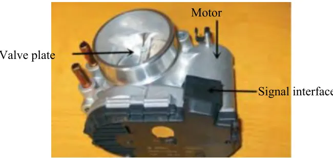
selector gear, a valve plate and nonlinear spring (Figure 1 and Figure 2) (Pan, Özguner, & Daǧci,
[image:15.612.163.488.484.638.2]2008).
Figure 1.1: External view of ETB. Valve plate
Motor
2
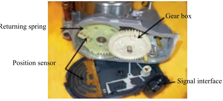
Figure 1.2: Internal view of ETB.
Traditionally, the throttle plate is connected directly by wire to the accelerator. So the
mass air rate controlled according to the driver demand. In this method, many internal and
external conditions such as fuel efficiency, road or weather condition to determine the throttle
plate angle are ignored. As a result, all this factor will negatively affect to the overall efficiency
of the engine (Mercorelli, 2009).
To determine accurately the throttle valve opening angle, an electronic control module
(ECM) is used to overcome the above deficiency. Electrical wire or fiber optic cable is used to
transmit the gas pedal and the measured signal to the central processing unit. It determines the
optimum reference opening angle and send the signal to the ETB to let the valve plate follow
the signal by using a proper controller (Bai & Tong, 2014) (“4.
Delphi_Drive_by_wire_2000-01-0556,” n.d.).
By using the ETB, there are some problem occur in this system which make the
controller design difficult. There are non-smooth nonlinearities including stick-slip friction,
gear backlash, and a nonlinear spring. Furthermore, the controller design becomes more difficult
because most of control algorithms assume that the uncertainty is smooth and/or satisfies the Returning spring
Position sensor
Gear box
3
matching condition, while as the parameters of these non-smooth nonlinearities cannot be
known accurately, the non-smooth and also unmatched parameter uncertainties inherently exist
(Pan et al., 2008) (Di Bernardo, Di Gaeta, Montanaro, & Santini, 2010).
By using a back-stepping approach, proportional integral derivative (PID) controller is
designed for matching uncertain systems and may be implemented in an unmatched uncertain
system (Pan et al. 2008). It is designed for the electronic throttle valve with the back-stepping
approach together with the feedback linearization technique (Ahmed AL-Samarraie & Khudhair
Abbas, 2012). The purpose of proportional integral derivative (PID) controller is to ensure the
valve plate follows the reference signal using continuous-time sliding mode concept by deriving
a controller with an observer. It is capable of coping with the uncertainties in the mathematical
model non-smooth nonlinearities, which exist in the control region and some unmodeled
mechanical phenomena, as a reason to select this method (Ahmed AL-Samarraie & Khudhair
Abbas, 2012; Pan et al., 2008). The designed time-optimal controller achieves considerably
faster transient, while preserving other important performance measures, like the absence of
overshoot and static accuracy within the measurement resolution (Ahmed AL-Samarraie &
Khudhair Abbas, 2012).
1.2 Problem Statement
Since the ETB consists of a direct current (DC) motor, a motor pinion gear, an
intermediate gear, a selector gear, a valve plate and nonlinear spring, there exist multiple
non-smooth nonlinearities including stick–slip friction, gear backlash, and a nonlinear spring, which
make controller design difficult (Ahmed AL-Samarraie & Khudhair Abbas, 2012; Pan et al.,
4
Due to the mechanical part moving in the ETB, certainly friction will occur. Friction is
the motion resistance of the moving object relative to another. In ETB, it is a nonlinear
phenomenon in which a force that produced by the resistance tends to oppose the motion of
throttle plate such as coulomb, static, viscous, stribeck, etc. (Pan et al., 2008) (Conatser,
Wagner, Ganta, & Walker, 2004). In this concept, static friction phenomena only have a static
dependency on velocity and the coulomb friction is considered.
The typical feature of the electronic throttle valve includes a stiff spring, which is used
as a fail-safe mechanism. When no power is applied, this spring act as a force to push the valve
plate to return to the position slightly above the closed position, so that the small amount of air
can be supplied into the engine in order to prevent a sudden lock of engine revolution while the
vehicle is in motion when no control is available (Jiao & Shen, 2012). Moreover, the motion of
the valve plate is limited between the maximum and minimum angles. These limited stops are
realized by a highly stiff spring, ideally with infinite gain.
Due to the clearance formed between a pair of mounted gears, there exists backlash
between gears where the gear backlash is another nonlinearity source in addition to friction and
the non-linear spring.
All this factor affected to reach an ideal air fuel ratio (stoichiometric about 14.7:1)
required by the engine especially when the drastically change to the velocity of the vehicle
required by the driver. Therefore, the ETB which is controlled by the electronic control module
5 1.3 Objective
The objectives of this project are as follows:
1. To develop an ETB model in MATLAB software.
2. To design a Nonlinear PID controller to obtain the desire throttle angle.
3. To compare the result with conventional PID.
1.4 Scope of Project
The scopes of this project are:
1. Study about ETB especially the parameter and its function. Also, study the
problem that occurs in this system to achieve the desire throttle angle.
2. This project only focuses on tuning simulation.
3. Perform the simulation by using MATLAB software.
4. Model the ETB provide by (Pan et al., 2008) using MATLAB Simulink
application.
5. Apply the model of non-linear PID controller by using MATLAB Simulink
6. Compare the result of conventional PID with the non-linear PID controller.
6 CHAPTER 2
LITERATURE REVIEW
2.1 Introduction
This chapter summarizes the previous well-known experimental and tuning method that
has been performed in the field of electronic throttle body. However, some important
explanation of this project will be explained first. A method for tuning electronic throttle body
will describe in this chapter.
2.2 Electronic Throttle Body (ETB)
Now a day, throttle body system is no longer a foreign component in the automotive
industry, but its use has become very popular and widespread. Electronic throttle body
necessitates the use of an electric actuator motor because there is no mechanical linkage between
the accelerator pedal and the throttle body. There are several reasons why electronic throttle
actuation is preferable to a conventional throttle cable:
a. The electronic systems are able to control all of the engine’s operation with the
exception of the amount of incoming air.
b. Only the correct amount of throttle opening will receive by the engine for any
7
c. The harmful exhaust emissions are kept to an absolute minimum and drivability
is maintained and ensured by the optimization of the air supply. Finer control can be
achieved because coupling the electronic throttle actuation to the adaptive cruise control,
traction control, idle speed control and vehicle stability control systems. (“Automotive
Applications of Sliding Mode,” n.d.)
The use of such a system has advantages over the conventional cable version by:
a. Make the system become simpler by reducing the number of moving parts by
eliminating the mechanical element of a throttle cable and using with fast responding
electronics. It requires minimum adjustment and maintenance.
b. Provides better response and economy because of the greater accuracy of data
improves the drive ability of the vehicle (Goodwin, Graebe, & Salgado, n.d.).
However, by using the electronic throttle body, there are some problem occur in this
system which make the controller design difficult. There are non-smooth nonlinearities
including stick-slip friction, gear backlash, and a nonlinear spring. Furthermore, the controller
design becomes more difficult because most of control algorithms assume that the uncertainty
is smooth and/or satisfies the matching condition, while as the parameters of these non-smooth
nonlinearities cannot be known accurately, the non-smooth and also unmatched parameter
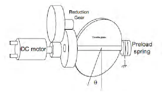
uncertainties inherently exist. (Conatser et al., 2004). A typical configuration of an ETB is
8
Figure 2.1: Electronic Throttle Body Schematic.
2.3 Nonlinearities
The nonlinearities, such as friction, nonlinear spring and gear backlash involved in the
electronic throttle body system make the controlling of opening throttle valve angle and to
realize a highly robust controller against uncertainties become difficult (Araki, n.d.), (Pan et al.,
2008).
2.3.1 Friction
Friction is the motion resistance of the moving object relative to another. It is a nonlinear
phenomenon in which a force that produced is tends to oppose the motion of throttle plate such
as coulomb, static, viscous, stribeck, etc. Only the coulomb friction is considered in this work.
Static friction phenomena only have a static dependency on velocity (Al-samarraie, 2012). The
9
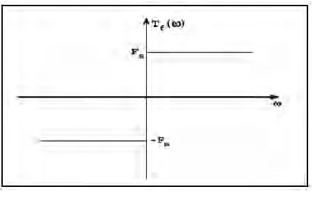
Figure 2.2: Coulomb friction.
Consequently, the Coulomb friction model mathematically is given by
𝑇𝑓(ɷ) = {
𝐹𝑠, ɷ > 0 0, ɷ = 0 − 𝐹𝑠, ɷ < 0
= 𝐹𝑠,sgn(ɷ) - (1)
where 𝐹𝑠,: is a positive constant (Ahmed AL-Samarraie & Khudhair Abbas, 2012).
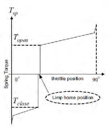
2.3.2 Nonlinear Spring
Electronic throttle body component typically includes a stiff spring, which is used as a
fail-safe mechanism. The purpose of this spring is to force the valve plate to return to the
position slightly above the closed position when no power is applied. So that, when no control
is available while the vehicle is in motion, the small amount of air can be supplied into the
engine to prevent a sudden lock of engine revolution. Moreover, the motion of the valve plate
is limited between the maximum and minimum angles. These limited stops are realized by a
highly stiff spring, ideally with infinite gain. (Ma, Shao, & Yurkovich, 2005). The characteristic
10
Figure 2.3: Nonlinear spring.
2.3.3 Gear Backlash
In addition to friction and the nonlinear spring, the gear backlash is another nonlinearity
source due to the clearance formed between a pair of mounted gears. The error in profile, pitch,
tooth thickness, helix angle, and canter distance, and run-out is the factors that affecting the
amount backlash needs in the gear transmission system. The greater the accuracy the smaller
the backlash needed. The way to reduce the gear backlash is by increasing the centre distances
between the gears (Circle, n.d.). The gear backlash between two gear shown in figure 2.4. When
writing the throttle valve mathematical model the nonlinearity coming from backlash