REAL TIME FINGER-VEIN RECOGNITION FOR AUTOMATIC DOOR ACCESS CONTROL
ALBERT NGAN BAN CHEW
This Report Is Submitted In Partial Fulfilment Of Requirements For The Bachelor Degree Of Electronic Engineering (Industrial Electronic)
Fakulti Kejuruteraan Elektronik dan Kejuruteraan Komputer Universiti Teknikal Malaysia Melaka
iii
“Saya akui laporan ini adalah hasil kerja saya sendiri kecuali ringkasan dan petikan yang tiap-tiap satunya telah saya jelaskan sumbernya.”
Tandatangan : ……… Nama Penulis : ALBERT NGAN BAN CHEW
iv
“Saya akui bahawa saya telah membaca karya ini pada pandangan saya/kami karya ini adalah memadai dari skop dan kualiti untuk tujuan penganugerahan Ijazah Sarjana Muda
Kejuruteraan Elektronik (Elektronik Industri).”
Tandatangan : ……….
Nama Penyelia : DR SYAFEEZA BINTI AHMAD RADZI
v
vi
ACKNOWLEDGEMENT
vii
ABSTRAK
viii
ABSTRACT
ix
TABLE OF CONTENTS
CHAPTER CONTENTS PAGES
PROJECT TITLE i
COMFIRMATION STATUS REPORT ii
RECOGNITION iii
SUPERVISOR AFFIRMATION iv
DEDICATION v
ACKNOWLEDGEMENT vi
ABSTRAK vii
ABSTRACT viii
TABLE OF CONTENT ix-xi
LIST OF TABLES xii
LIST OF FIGURES xiii-xiv
LIST OF ABBREVIATIONS xv
I INTRODUCTION
1.1 Project Introduction 1-2
1.2 Objectives 3
1.3 Problem Statement 3-4
1.4 Scope Of Work 4
II LITERATURE REVIEW
2.1 Finger-Vein Biometric System 5
2.1.1 Type Of System 6
x
2.2 Type Of Camera 8
2.2.1 CMOS Camera 8
2.2.2 CCD Camera 9
2.3 Capturing Finger-Vein Method 9-10
2.3.1 Light Reflection Method 10-11 2.3.2 Light Transmission Method 11-12
2.4 Image Quality Inspection 12-13
2.5 Image Processing in Vein Biometric System 13 2.5.1 Related Work: Conventional Image
Processing 13-15
2.5.2 Related Work: Computational
Intelligence 15-17
2.6 Summary Related Of Works 17
III PROJECT METHODOLOGY
3.1 Proposed Project’s Block Diagram 18
3.2 Hardware 19
3.2.1 Raspberry Pi 3 19
3.2.2 CMOS Camera 20
3.2.3 NIR Illuminating Circuit 20-21
3.2.3.1 Logic Converter 22
3.2.3.2 Light Transmission Method 22-23 3.2.4 Image Quality Asessment 23-24
3.3 Software 25
3.4 Image Processing Technique 26
3.4.1 Preprocessing 26-27
3.4.1.1 CLAHE 27-28
3.4.1.2 Image Normalization 28 3.4.1.3 Non-Local Denoising 29 3.4.1.4 Low Pass Filter (Gaussian
Blur) 29
3.4.1.5 Adaptive Thresholding: Mean 30
xi
3.4.1.7 Inverting Image 30
3.4.2 Feature Extraction 31
3.4.2.1 Thinning Algorithm 31 3.4.2.2 Minutiae Points 31-32
3.4.3 Matching Strategy 32
3.4.3.1 Alignment 33-34
3.4.3.2 Modified Hausdorff Distance 35
3.5 Biometric Performance 35
3.5.1 FAR(False Acceptance Rate) 35-36 3.5.2 FRR(False Rejection Rate) 36-37
3.5.3 EER(Equal Error Rate) 37-38
IV RESULTS AND DISCUSSION
4.1 Finger-Vein Identification System 39-42
4.2 Graphic User Interface (GUI) 43-46
4.3 PWM Analysis 47
4.4 2D Entropy Analysis 48
4.5 Biometric Performance(Equal Error Rate) 48-51
4.6 Cost Comparison 52
4.6.1 Finger-Vein Identification Device Cost 52 4.6.2 Comparison With Market Price 52-53
V CONCLUSION
5.1 Concluding Remark 54
5.2 Future Work Recommendation 54-55
xii
LIST OF TABLES
No TITLE PAGES
1.1 Comparison of major biometrics method 2
2.1 Related work using conventional image processing technique 14 2.2 Related work using computational intelligence 16
3.1 Cross Number Property For Minutiae Points 32
4.1 Finger-Vein Identification Device Cost 52
xiii
LIST OF FIGURES
No TITLE PAGES
2.1 Enrollment And Authentication Process In Finger-Vein Biometric Recognition System
5
2.2 Identification System 6
2.3 Verification System 7
2.4 Image Sensors Converted To Electrical Signal 8 2.5 CMOD Image Sensor’s Charge Move In The Sensor 8 2.6 CCD Image Sensor’s Charge Move Across The Sensor 9 2.7 Both Types Of Method To Capture The Finger-Vein 10
2.8 Light Reflection Method 11
2.9 Resulting Image Using Light Reflection Method 11
2.10 Light Transmission Method 12
2.11 Resulting Image Using Light Transmission Method 12
3.1 Project System’s Block Diagram 18
3.2 Raspberry Pi 3 Model B 19
3.3 Raspberry Pi 3 Technical Specification 19
3.4 Raspberry Pi Camera 20
3.5 NIR Illuminating Circuit Diagram In Proteus 21
3.6 NIR Illuminating Layout Diagram In Proteus 21
3.7 Logic Converter 22
3.8 Light Transmission Method 23
3.9 Flow Chart Of The Image Quality Assessment 24
3.10 OpenCV and Python’s Logo 25
3.11 Flow Chart From Hardware To Image Processing 26 3.12 Flow Of Preprocessing Steps Before Feature Extraction 27
3.13 CLAHE's Histogram Before And After 28
xiv 3.15 Convolution Mask Of Gaussian Low Pass Filter 29
3.16 Type Of Minutiae Point 31
3.17 Fitted Line With RANSAC 33
3.18 Example Of Affine Transform 34
3.19 Modified Hausdorff Distance 35
3.20 False Acceptance Rate Graph 36
3.21 False Rejection Rate Graph 37
3.22 Equal Error Rate Graph 38
4.1 Finger-Vein Identification's Device 39
4.2 Finger-Vein Device Interior 39
4.3 Servo Motor Used To Demonstrate The Door 40
4.4 NIR Illuminating Circuit And Camera 40
4.5 The Finger-Vein Identification's Device Flow 42
4.6 Main Page Of GUI 43
4.7 Check Register Fail 44
4.8 Check Identification Fail 44
4.9 Register Successful 45
4.10 Identification Fail 46
4.11 Identification Successful 46
4.12 Graph Of Current Against PWM Level 47
4.13 Graph Of Voltage Against PWM Level 47
4.14 Graph Of PWM Level Against 2d Entropy Value 48 4.15 Equal Error Rate Of Design's Biometric Device Normal MHD 49 4.16 Equal Error Rate Of Design's Biometric Device Normal
Mhd(Zoomed)
xv
LIST OF ABBREVIATIONS
CCD - Charge Couple Device
CLAHE - Contrast Limited Adaptive Histogram Equalization CMOS - Complementary Metal Oxide Semiconductor CNN - Convolution Neural Network
DNN - Deep Neural Network ERR - Equal Error Rate FAR - False Acceptance Rate FRR - False Rejection Rate KNN - K-Nearest Neighbor LED - Light Emitting Diode
MHD - Modified Hausdorff Distance NIR - Near Infrared
1
CHAPTER I
INTRODUCTION
1 HEADING 3 – CHANGE COLOR TO WHITE BEFORE PRINTING
1.1 Project Introduction
This project is to make a real-time finger-vein recognition for automatic door access control system. It is a project where by using a person’s finger-vein to give access through a door. In other words finger-vein is used as a personal password. This project focuses more towards the real-time finger-vein recognition part as that area in this project is more complex than the automatic door section.
2 Biometrics, in which the measurements are related to human characteristics can be used to replace the conventional key or password. Biometrics uses parts of the body which are found to be distinctive from one person to another. Example of biometrics identifiers such as fingerprint, vein, iris, face, voice and many more. By using a biometric trait as the password, human carelessness will no longer pose a problem because a biometric password uses the part of the body as the password, there is no way to carelessly forget or even easily forge a person’s biometric trait. Besides that, it is very unique as it differs from one person to another, which makes it a unique password that belongs to only a person. Thus, the biometric password could distinguish a person as it is personally unique.
Finger-vein biometric is a new biometric method which utilizes the vein patterns inside one’s fingers for personal identity identification. Vein patterns are different for each finger and for each person; and as they are hidden underneath the skin’s surface, forgery is extremely difficult [1]. Besides that using finger-vein biometric as the authentication is better in several aspects compared to other biometric traits. Table 1.1 shows the comparison of major biometrics method.
[image:17.612.117.544.514.637.2]From Table 1.1, it can be seen that by using vein biometric, the cost is moderate at the same time it has very great accuracy and anti-forgery characteristics. Table 1.1 supports that veins are better suited compared to other biometrics method.
Table 1.1: Comparison of major biometrics method [1]
3 1.2 Objectives
The main agenda in this project is to design and develop a system which functions in real-time that can capture finger-vein images followed by processing the image for recognition to allow or restrict access through an automatically controlled door. The sub-objectives regarding the main agenda are as follow:
- To create a finger-vein identification system using Raspberry Pi to overcome the insufficient memory capacity problem
- To solve the uneven illumination problem when capturing finger-vein images - To create a low-cost finger-vein identification system
1.3 Problem Statement
To design and develop a unified system which can work in real-time, capture images, and ‘process’ images would surely require a lot of memory to execute. To work in real-time, the entire system’s process must be executed at a very short time. Besides that, by capturing images, it requires memory to keep those images into the database to be kept as a comparison in the future for authentication. Thus, a huge memory is required to keep the images. Besides, processing the images pixel by pixel would use up a lot of processing speed alongside with the system’s memory. Therefore, it is a problem for a low-memory capacity microcontroller to be used which disallow images to be kept and process in the microcontroller.
4 sufficient intensity of the NIR light is a major problem to be solved as the quality of the image would affect the authentication part later in the system.
1.4 Scope Of Work
In this project, the scope of work will be divided into mainly three parts. The parts are hardware, software and performance measures.
The hardware is the physical aspects of the system such as the camera, NIR light illuminating circuit, door locking circuit. The scope of the hardware would be to use the Raspberry Pi 3 as the microcontroller together with the pi camera which had its IR filter removed alongside with a matrix of NIR LED’s to be used as the light source to shine on to the finger.
The software is the internal aspect of the system where in this project, Python would be used as the platform to code the processes in the system. Python is used to do all image processing techniques including the performance measures as well. The main library used for the image processing in Python is OpenCV.
5
CHAPTER II
LITERATURE REVIEW
2 HEADING 3 – CHANGE COLOR TO WHITE BEFORE PRINTING
2.1 Finger-Vein Biometric System
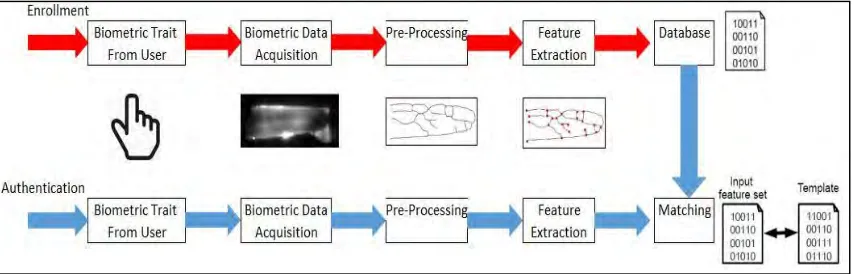
[image:20.612.118.545.471.608.2]A Biometric recognition system comprises of two types of stages which are enrollment and authentication. The enrollment and authentication process is as shown in Figure 2.1. In enrollment stage, the finger-vein in this case would have its feature extracted and keep in the database for future authentication use. For authentication process, it can be used in either verification or identification. The finger-vein feature extracted will then be used to compare with the available information in the database that had been done in the enrollment stage.
6 2.1.1 Type Of System
2.1.1.1Identification System
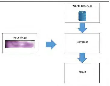
Identification systems are described as a 1-to-n matching system, where ‘n’ is the total number of features in the database, because the system would match the extracted feature to the whole database in the system. This system is use to identify who is that person with the particular features presented.
[image:21.612.147.511.397.681.2]By referring to Figure 2.2, the user would directly present their biometric trait into the system, then the system would cross check the biometric trait with every template in the database. Identification system may require more time as it cross checks with every template in the database but it requires less hardware in comparison with verification system as it does not need to have any identification process. Furthermore, identification system is only applicable to only a system which have small number of database due to time constraints.
7 2.1.1.2Verification System
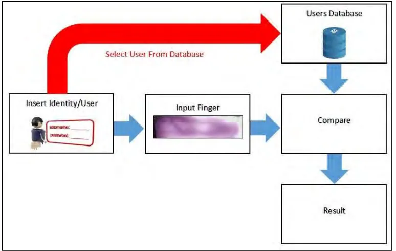
Verification systems are described as a 1-to-1 matching system because the system would match the extracted feature to only a certain database in the system. Since verification is to check whether the features presented is the right person or not. For example, an individual presents himself or herself as a specific person, the system will then only compare the finger-vein features to that specific person’s database. This will reduce the amount of time in comparing the features as the amount of template features compared is lesser.
[image:22.612.135.522.376.621.2]By referring to Figure 2.3, before inserting the biometric features, the user would need to insert a tool to prove the user, it could be a username and password, could be RFID could be anything before inserting the biometric trait. The biometric trait will then be compared with only that particular person’s template instead of the whole database. Verification system is faster compared to verification system but requires more hardware.
8 2.2 Type Of Camera
[image:23.612.267.389.218.309.2]There are two types of camera to be chosen which is CMOS (Complementary Metal Oxide Silicon) and CCD (Charged Coupled Device). Most camera’s in the market uses CMOS camera especially in webcams as the use of CCD camera in webcam had stopped since the year 2012. CCD camera still can be found in expensive cameras where mostly used in astronomy.
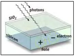
Figure 2.4: Image sensors converted to electrical signal
Both type of image sensors CMOS and CCD both uses the same concept to convert light which is by using the photoelectric effect to create electrical signal from light.
2.2.1 CMOS Camera
CMOS image sensors uses transistor at each pixel to move the charge through traditional wires. Typically a CMOS image sensors includes amplifiers, noise-correction, and digitization circuits, enabling the sensor to output digital data directly at each pixel.
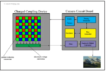
[image:23.612.213.444.531.687.2]9 2.2.2 CCD Camera
[image:24.612.223.433.218.362.2]In the CCD image sensor, the CCD use a special manufacturing process to transport charge across the chip without distortion. The CCD image sensor also, every pixel’s charge is transferred to a very limited output unlike the CMOS where every pixel has its own output. The CCD image sensor is proven to produce a better image than the CMOS image sensor but at a higher cost.
Figure 2.6: CCD image sensor’s charge move across the sensor
![Table 1.1: Comparison of major biometrics method [1]](https://thumb-us.123doks.com/thumbv2/123dok_us/72226.6781/17.612.117.544.514.637/table-comparison-of-major-biometrics-method.webp)