INTEGRATION OF AN AUTOMATED GUIDED VEHICLE SYSTEM
WITH A PROGRAMMABLE LOGIC CONTROLLED MATERIAL
HANDLING
This report submitted in accordance with requirement of the University Teknikal Malaysia Melaka (UTeM) for the Bachelor Degree of Manufacturing Engineering
(Robotics and Automation)(Hons.)
by
CHIAM CHUN HONG B051310102 930609-07-5725
UNIVERSITI TEKNIKAL MALAYSIA MELAKA
BORANG PENGESAHAN STATUS LAPORAN PROJEK SARJANA MUDA
TAJUK: Integration of an Automated Guided Vehicle System with a Programmable Logic Controlled Material Handling
SESI PENGAJIAN: 2016/17 Semester 2
Saya CHIAM CHUN HONG
mengaku membenarkan Laporan PSM ini disimpan di Perpustakaan Universiti Teknikal Malaysia Melaka (UTeM) dengan syarat-syarat kegunaan seperti berikut:
1. Laporan PSM adalah hak milik Universiti Teknikal Malaysia Melaka dan penulis. 2. Perpustakaan Universiti Teknikal Malaysia Melaka dibenarkan membuat salinan
untuk tujuan pengajian sahaja dengan izin penulis.
3. Perpustakaan dibenarkan membuat salinan laporan PSM ini sebagai bahan pertukaran antara institusi pengajian tinggi.
4. **Sila tandakan (√ )
SULIT
TERHAD
√ TIDAK TERHAD
(Mengandungi maklumat yang berdarjah keselamatan atau kepentingan Malaysiasebagaimana yang termaktub dalam AKTA RAHSIA RASMI 1972)
(Mengandungi maklumat TERHAD yang telah ditentukan oleh organisasi/badan di mana penyelidikan dijalankan)
Alamat Tetap:
NO. 76, Jalan Teratai Indah, Taman Teratai Indah,
Butterworth, Pulau Pinang.
Tarikh: 29/05/2017
Disahkan oleh:
Cop Rasmi:
Tarikh: _______________________
i
DECLARATION
I hereby, declared this report entitled “Integration of an Automated Guided Vehicle System with a Programmable Logic Controlled Material Handling”
is the results of my own research except as cited in reference.
Signature : ………..
Author’s Name : CHIAM CHUN HONG
ii
APPROVAL
This reported is submitted to the Faculty of Manufacturing Engineering of Universiti Teknikal Malaysia Melaka as a partial fulfillment of the requirements for the degree of Bachelor of
Manufacturing Engineering (Robotics & Automation) (Hons). The members of the supervisory committed are as follow:
………..
I
ABSTRAK
ii
ABSTRACT
iii
DEDICATION
Only
my respected grandfather and grandmother, Chiam Ah Bak and Siah Geet Suan my beloved father, Chiam Kok San
my appreciated mother, Lim Ai Tee
my adored sisters, Xue Chyi, Xue Mei and Xue Jing
iv
ACKNOWLEDGEMENT
First, I would like to take this opportunity to thank my respected supervisor, Ir. Dr.-Ing. Azrul Azwan Bin Abdul Rahman CEng for his precious time of encouraging, sharing, mentoring and patient that was given throughout the entire project. Without his assistance and knowledge, this project would not have been successful.
Besides, I also want to thank my family for their love and support throughout my life. They have given me discipline and drive to tackle any task with enthusiasm. Without their love and support, my studies journey would not be so smoothly.
In addition, I would like to thank lecturer of UTeM for teaching the knowledge of manufacturing engineering that was extremely useful for my project. I would like to thank the faculty member who served on the laboratory staffs and the master students for them cooperate and generous for their expertise.
Last but not least, I would like to give special thanks to my friend who gives me much motivation and cooperation mentally in completing this report.
v
TABLE OF CONTENTS
ABSTRAK i
ABSTRACT ii
DEDICATION iii
ACKNOWLEDGEMENT iv
TABLE OF CONTENTS v
LIST OF TABLES viii
LIST OF FIGURES ix
LIST OF ABBREVIATIONS xii
CHAPTER 1: INTRODUCTION
1.1 Background 1
1.2 Problem Statement 2
1.3 Objectives 3
1.4 Scope 3
CHAPTER 2: LITERATURE REVIEW
2.1 Material Handling 4
2.1.1 AGVs 5
2.1.1.1 Free Ranging and Autonomous 7
2.1.1.2 Consideration Implementation 8
2.1.1.3 Mapping, Localization, Path Planning and Navigation 9
2.1.1.4 Communication 10
2.1.1.5 LAN 12
2.1.1.6 WLAN and Wi-Fi 13
2.1.1.7 Control System 15
2.1.1.8 Programming Language 17
vi
2.1.2.1 System Design 19
2.1.2.2 Consideration Implementation 19
2.1.2.3 Control System 20
2.2 Material Handling System Integration 30
2.2.1 Open System Interconnection (OSI) protocol 32
CHAPTER 3: METHODOLOGY 34
3.1 Overall Methodology 34
3.2 Initial Assessment 35
3.3 Development of Communication System 36
3.4 Software and Programming 38
3.5 Data Transfer 40
3.6 Verification, Improvement, and Implementation of the Project 41
CHAPTER 4: RESULTS AND DISCUSSION 43
4.1 Validation Table 43
4.2 Connection of the complete system 44
4.3 Connection with AGV system 47
4.3.1 Connection of C++ and ARIA 48
4.3.2 Connection of ARIA and MobileSim 53
4.3.3 Connect to the Real AGV P3-AT 60
4.4 Connection with Conveyor System 63
4.4.1 Connection of C++ and QuickOPC 64
4.4.2 Connection between QuickOPC and MatrikonOPC Server for Omron PLC 66 4.4.2.1 Coding for Write Data to OPC Server 67 4.4.2.2 Coding for Read Data from OPC server 70 4.4.3 Connection between the MatrikonOPC Server and MatrikonOPC Explorer 71
4.4.4 Connect to the real Omron CP1L PLC 76
4.5 Scenario for Verification 76
vii
CHAPTER 5: CONCLUSION AND RECOMMENDATIONS 79
5.1 Conclusion 79
5.2 Suggestions and Future Works 80
REFERENCES 81
APPENDIX A 87
APPENDIX B 88
APPENDIX C 89
APPENDIX D 92
APPENDIX E 96
viii
LIST OF TABLES
ix
LIST OF FIGURES
Figure 2.1: Simple example of material handling system 5
Figure 2.2: Example of an AGV 7
Figure 2.3: Pioneer 3-AT robot 8
Figure 2.4: The procedure of the data transmits 11
Figure 2.5: Example of the LAN networking 13
Figure 2.6: Example of the Wi-Fi communication 14
Figure 2.7: Example of the computer control system 16
Figure 2.8: Example of the Belt Conveyor 18
Figure 2.9: Block diagram of DCS 22
Figure 2.10: Example of PLC 24
Figure 2.11:Example of PLC system 26
Figure 2.12: Component of the PLC to control the conveyor system 27
Figure 2.13: Example of the LD 28
Figure 2.14: Example of the system integration 32
Figure 2.15: Example of the data transferring through OSI protocol 33
Figure 3.1: Overall Methodology 34
Figure 3.2: Pioneer 3 research AGV 35
Figure 3.3: Omron SYSMAC CP1L-E 36
Figure 3.4: Communication between AGV and PLC conveyor system through host computer 36
Figure 3.5: PC-104 card 37
Figure 3.6: Data transfer from AGVs to host computer 40
Figure 3.7: Data transfer from PLC conveyor system to AGVs 41
Figure 3.8: Example of the validation table 42
x
Figure 4.2: Header for the main coding. 46
Figure 4.3: Coding for connect both system. 46
Figure 4.4: Desktop situation when debugging all system. 47 Figure 4.5: The software logo that uses to communication between the C++ sotware and the
AGV simulation. 48
Figure 4.6: C++ software properties setting. 49
Figure 4.7: C++ software general configuration properties. 50 Figure 4.8: C++ software adding library in Additional Dependencies. 50
Figure 4.9: C++ software adding Aria library 51
Figure 4.10: C++ software changing Runtime Library. 52
Figure 4.11: Adding Aria.h into the coding 52
Figure 4.12: Drawing map by using Mapper3Basic. 53
Figure 4.13: Select the robot and load the map 54
Figure 4.14: After loaded the map 54
Figure 4.15: The example coding of AGV moving forward. 55 Figure 4.16: The example coding of AGV moving backward. 56 Figure 4.17: The example coding for the AGV to rotate anticlockwise. 56 Figure 4.18: The example coding of AGV clockwise rotate. 57
Figure 4.19: The example coding of AGV stopping. 58
Figure 4.20: Simulation AGV moving forward 58
Figure 4.21: Simulation AGV after moving forward and start to rotate 59 Figure 4.22: Simulation AGV after finish rotate and start to move forward again 59
Figure 4.23: IP address checking 61
Figure 4.24: VNC viewer connect to VNC server 61
Figure 4.25: Real robot moving. 62
Figure 4.26: The software logo that uses to communication between C++ and PLC 63
Figure 4.27: Adding a new header file. 64
Figure 4.28: Giving the new header files name QuickOPC. 65
Figure 4.29: Adding OPC library into the coding 65
xi
Figure 4.32: The coding that writes the value to False. 68 Figure 4.33: The coding that makes an array for the number of items. 68
Figure 4.34: Coding for Write data from array 69
Figure 4.35: Coding for select the server-class and item id to read value 70 Figure 4.36: The coding that makes an array for the number of items. 70
Figure 4.37: Coding for read data to array 71
Figure 4.38: MatrikonOPC server create a new alias 72
Figure 4.39: Insert detail of alias 73
Figure 4.40: MatrikonOPC Explorer is connecting to the server. 73 Figure 4.41: Adding tag into the MatrikonOPC Explorer Group 0. 74
Figure 4.42: Adding available tags. 75
Figure 4.43: The tags are added and can be read the value from MatrikonOPC server. 75
xii
LIST OF ABBREVIATIONS
ADC - Analog-to-Digital Converter
AGV - Automated Guided Vehicle
CAN - Controller Area Network
CSMA/CA - Carrier Sense Multiple Access with Collision Avoidance DAC - Digital-to-Analog Converter
DCS - Discrete Control System
FBD - Function Block Diagram
IC - Integrated Circuit
IL - Instruction List
IPCF - Industrial Point Coordination Functions
IPCF-MC - Industrial Point Coordination Function – Management Channel ISO - International Organization for Standardization
I/O - Input and Output
IWLAN - Industrial Wireless LAN
LAN - Local Area Network
LAWN - Local Area Wireless Network
LD - Ladder Diagram
LED - Light Emitting Diodes
OLE - Object Linking and Embedding OPC - OLE for Process Control
OS - Operating System
OSI - Open System Interconnection
PC - Personal Computer
PCMCIA - Personal Computer Memory Card Industry Association PLC - Programmable Logic Controller
RF - Radio Frequency
ROI - Return of Investment
xiii
SFC - Sequential Function Chart
ST - Structural Text
Wi-Fi - Wireless Fidelity
1
CHAPTER 1
INTRODUCTION
1.1Background
Manufacturing industry plays an important role and made a large influence in the economic growth. But, the manufacturing industry need to face a lot of challenges due to globalization in this 21st century (Ong, 2015). So, the manufacturing industry is always searching for improvement. To improve it directly or indirectly, one of the methods is to integrate the system each other to increase the productivity. There are a lot of systems in manufacturing industrial such as material handling system, packaging system, fabrication system and so on (Kajan et at., 2013), (Jaiganesh et at., 2014).
Material handling system involves short distance movement within the confines of a building or between a building and a transportation vehicle. It utilizes a wide range of manual, semi-automated, and automated equipment and included consideration of the protection, storage, and control of material throughout their manufacturing, warehousing, distribution, consumption, and disposal (Aized, 2010). In a simple way to explanation, material handling system is a system concerned about loading, moving and unloading of materials. Some example of the material handling system is Automated Guided Vehicle (AGV) system and conveyor system.
2
system (Wu et at., 2012). The example of AGV are towing AGV, unit-load AGV, pallet truck AGV, fork truck AGV and others (Wu et at., 2012).
Conveyor systems are especially useful in the application involving the transportation of heavy or bulky materials. Conveyor systems allow quick and efficient transportation for a wide variety of materials which make them very popular in the material handling and packaging industries (Ong, 2015). There is a positive growth for conveyor system on manufacturing industry (TECHNAVIO, 2016). The example of the conveyor system likes pneumatic conveyor, vibrating conveyor, flexible conveyor, vertical conveyor and others. There are many conveyor systems is using Programmable Logic Controller (PLC) to control it.
PLC is an industrial digital computer which is flexible, ruggedized and adapted for the control of manufacturing processes, such as assembly lines, or robotic devices, or any activity that requires high-reliability control and ease of the programming and process fault diagnosis (MAKOX, 2014), (Aized, 2010). By using the PLC, the output results must be produced in response to input condition within a limited time.
In future, the material movement should be fully integrated to form a coordinated, operational system which including receiving, inspection, storage, production, assembly, packaging, unitizing, order selection, shipping, transportation and the handling of return (Aized, 2010).
1.2Problem Statement
3
automatically. To link the whole system together, we need to do it step by step. So, the research starts from integrating the AGV and PLC material handling system. In addition, there are just a few of research being done about the integration system between AGVs and the material handling system. So, to prove the AGVs works on integrating with material handling system, we try to communicate each other through experimentation. By integration difference system together, it can be improving the productivity and decrease the cost efficiency while the whole system in the industry can be more synchronize without any operator interrupt after few years.
1.3Objectives
The objectives of this project are:
(a) To establish the communication between AGV and PLC conveyor system using communication protocol.
(b) To verify the integration capability between AGV and PLC conveyor system through experimentation.
1.4 Scope
The scope works for this project are:
(a) The type of material handling system is using conveyor system and AGV system. (b) The type of AGVs is using Pioneer 3-AT (P3-AT) research AGV.
(c) The conveyor system is using Omron PLC to control.
4
CHAPTER 2
LITERATURE REVIEW
2.1Material Handling
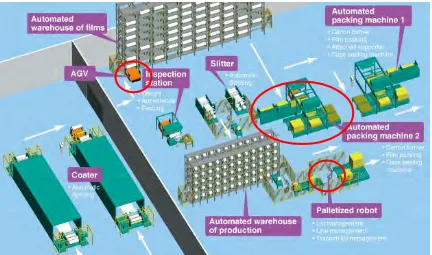
5
Figure 2.1: Simple example of material handling system (Toray, 2016)
2.1.1 AGVs
6 (a) vehicles
Vehicles are the most important elements of an AGVs as they perform the actual transportation tasks. All vehicles are design individually according to their specific working tasks, working condition and working environment (Schulze et at., 2008). Vehicle can be classified as toward AGV, unit load AGV, pallet truck AGV and fork truck AGV (Wu et at., 2012), (Vosniakos and Mamalis, 1990).
(b) guidance and information transfer system
Most of them will using signal paths, lane paths or signal beacons for navigation. The examples of the sensors that AGV will use to senses are optical sensors, laser scanner, magnetic sensors and also camera (Wu et at., 2012), (Vosniakos and Mamalis, 1990).
(c) traffic control system
The traffic control system covers superordinate control component. It tasks is administration of the transportation orders, the optimization of schedules, the communication with other control system. The system also provides graphical visualization and statistical analysis (Schulze et at., 2008). The AGV routing method can be classified from the viewpoint of trajectory shape which is single loop or bi-directional (Kajan et at., 2013).
(d) pick-up and deposit station and load transfer equipment (Vosniakos and Mamalis, 1990)
7
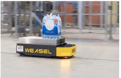
[image:24.612.225.421.359.486.2]The advantages of AGVs is flexibility system, safety technology, and accuracy and productivity. It is a flexibility system due to the vehicle can quickly reprogram to change direction, path or operation. The system also can eliminate the need for expensive retrofitting and new directions, tasks, and work cells can be created almost instantaneously without the need for physical equipment installation. Besides, the AGVs is safety due to it can avoiding interference with human or building. It also can work at the environment that may be not suitable to human operators. In addition, the AGVs is accuracy after combined with Radio Frequency (RF) technology and it can operate at a fixed rate to meet a predictable metric for operational activity (Vosniakos and Mamalis, 1990), (Jaiganesh et at., 2014). Development of the AGVs plays the major role in industry to improve the technology of the material handling system (Kajan et at., 2013), (Jaiganesh et at., 2014). Figure 2.2 show that an AGV is transporting the material.
Figure 2.2: Example of an AGV (Schafer, 2015)
2.1.1.1 Free Ranging and Autonomous