
Open source conversion of Stratasys FDM Vantage X rapid prototyping machine : a thesis submitted in partial fulfilment of the requirements for the degree of Master of Engineering in Mechatronics at Massey University, Albany, New Zealand
132
0
0
Full text
(2) Open-Source Conversion of Stratasys FDM Vantage X Rapid-Prototyping Machine. A thesis presented in partial fulfilment of the requirements for the degree of Master of Engineering in Mechatronics at Massey University, Albany,. New Zealand. George Graham Hare 2014.
(3) Abstract 3D Printing or Additive Manufacturing is quickly redefining how companies design and develop products (Maxey, 2014). Increasingly, with advances in technology and materials, end-use parts are now being manufactured. Wellington Drive Technologies Limited (WDTL), a world leading supplier of energy saving, electronically commutated motors (ECM) are based in Albany, Auckland.. They use fused deposition modelling (FDM) to prototype new. products and concepts. WDTL suffered a failure of a Stratasys FDM Vantage X machine used to 3D print prototype parts. The cost of rectifying the problem put the machine beyond economic repair. The machine was therefore gifted to Massey University, Albany. Mechanically the machine was in good working order, it made sense therefore to attempt to resurrect the machine for research purposes. However, due to the cost of OEM repairs, and the associated research limitations, it was decided that where possible, open-source solutions should be sought. The purpose of this dissertation is to prove the viability of replacing closedsource proprietary hardware and software solutions with open-source.. The. electronics and firmware were designed around the MakerBot Thing-O-Matic while ReplicatorG was used for the front end, all of which are open-source. Ironically on the 19th June 2013, almost a year after starting this project, Stratasys bought MakerBot, taking a big stake in the consumer based 3DPrinter market. Subsequent releases of Makerware (MakerBot's successor to ReplicatorG) have been made closed-source.. i.
(4) Acknowledgements Professor Olaf Diegel and Associate Professor Johan Potgieter of the School of Engineering and Advanced Technology (SEAT), Massey University, Albany Campus without whom this project would never have happened. Garry Armstrong and Ashley Reid for their support during my studies. Ryan Brookes and Brian Young of the Defence Technology Agency (DTA) for allowing me to dedicate my time and efforts to further my knowledge of additive manufacturing in general for the benefit of the New Zealand Defence Force. My wife, Alexandra for her constant support and re-assurance and not least, my sons Dominic and Thomas, for their understanding and patience over the past two years. Also to the too numerous to mention friends and colleagues who have come through my lab over the past two years to see what it is I'm going on about at the lunch table.. ii.
(5) Table of Contents Abstract..................................................................................................................i Acknowledgements...............................................................................................ii List of Figures........................................................................................................v List of Tables.......................................................................................................viii 1 Introduction.......................................................................................................1 1.1 OEM Machine Limitations........................................................................2 1.1.1 Materials...........................................................................................3 1.1.2 Process Parameter Control..............................................................4 2 Literature Review..............................................................................................6 2.1 Definition..................................................................................................6 2.2 Additive Manufacturing Technologies......................................................6 2.3 Fused Deposition Modeling (FDM)........................................................12 2.4 The Open-Source Model.......................................................................13 2.5 Development of Open-Source FDM Machines.....................................15 3 Mechanical Design..........................................................................................21 3.1 Motors....................................................................................................21 3.1.1 Servo Motor Theory........................................................................21 3.1.2 Stepping Motor Theory...................................................................24 3.2 Front Panel Controller...........................................................................30 3.3 Extruder Head Solenoid........................................................................33 3.4 Other Hardware Modifications...............................................................34 4 Electrical Design.............................................................................................35 4.1 Power Supply........................................................................................35 4.2 Extruder Head.......................................................................................55 4.3 Motherboard..........................................................................................69 5 Firmware Development...................................................................................75 5.1 Extruder Controller................................................................................76 5.2 Power Supply Controller........................................................................77 5.2.1 Additional UART.............................................................................77 5.2.2 UPSPacket Class...........................................................................78 5.2.3 Heater Control................................................................................79 5.2.4 Digital Output Control Functions....................................................84. iii.
(6) 5.2.5 AC and DC PSU Status..................................................................85 5.2.6 Tool Commands.............................................................................85 5.3 Motherboard..........................................................................................86 5.4 Print Reliability.......................................................................................90 6 Software Design..............................................................................................92 6.1 ReplicatorG 0040...................................................................................92 6.2 ReplicatorG 0037...................................................................................95 7 Calibration.....................................................................................................100 8 Testing...........................................................................................................106 8.1 Temperature.........................................................................................106 8.2 Flow & Feed Rate................................................................................109 8.2.1 Manual Base Layer Parameters..................................................109 8.2.2 Manual Interface Layer Parameters.............................................110 8.2.3 Manual First Layer Parameters....................................................110 8.2.4 Manual Remaining Layer Parameters..........................................111 8.2.5 Result of Manual Coded Test Box................................................111 8.3 Skeinforge Raft Modifications..............................................................112 8.3.1 Raft Modification Discussion........................................................113 8.4 Automatic gcode Generation...............................................................113 8.4.1 Results of Automatically Coded Box............................................114 8.5 Chamber Temperature.........................................................................114 9 Conclusion.....................................................................................................116 References........................................................................................................118. iv.
(7) List of Figures Figure 1: FDM Machine General Design (Crump, 1992)....................................12 Figure 2: RepRap Darwin (http://en.wikipedia.org/wiki/File:Reprap_Darwin.jpg) ............................................................................................................................15 Figure 3: RepRap Mendel (http://www.cnccookbook.com/img/OthersProjects/3DPrinting/reprap.jpg)........16 Figure 4: MakerBot Replicator (http://www.zahncenternyc.com/wpcontent/uploads/2014/08/MakerBot-Replicator.jpg)...........................................17 Figure 5: Simplified AC Motor Control................................................................22 Figure 6: Quadrature Incremental Encoder Output Waveform (http://sine.ni.com) ............................................................................................................................24 Figure 7: Cross-section through Single-Stack VR Stepping Motor....................25 Figure 8: Cross-section of three-stack variable reluctance stepper motor (http://www.industrial-electronics.com)...............................................................26 Figure 9: 2-Phase Hybrid Stepper Motor (http://www.engineersgarage.com). . .27 Figure 10: Stratasys FDM Vantage X Front Panel Controller.............................30 Figure 11: Message Snooping using Dick Smith Electronic RS-232 to USB Adapters..............................................................................................................31 Figure 12: Replacement FPC.............................................................................33 Figure 13: OEM Power Supply PCB...................................................................36 Figure 14: Incoming Supply Distribution.............................................................39 Figure 15: Heater Control...................................................................................39 Figure 16: High Voltage DC Rectifier..................................................................40 Figure 17: Auxilliary Power Control.....................................................................41 Figure 18: Power Supply Board - Top Copper....................................................41 Figure 19: Power Supply Board - Bottom Copper..............................................42 Figure 20: Low-Side Switching Modification.......................................................42 Figure 21: Arduino Mega Redundant Power Supply..........................................43 Figure 22: Serial Interface Board in UPS...........................................................44 Figure 23: Serial Communications......................................................................45 Figure 24: RS-485 Serial Interface.....................................................................46 Figure 25: RS-485 Interface PCB.......................................................................47 Figure 26: MAX31855 Thermocouple Interface..................................................48. v.
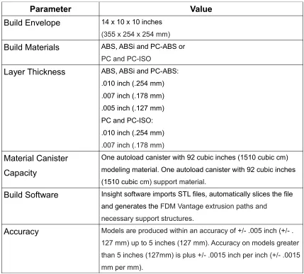
(8) Figure 27: E-Stop Protected Contactor Control..................................................49 Figure 28: DC Power Rail Monitoring.................................................................50 Figure 29: Arduino Mega 2560 Power Supply Controller...................................50 Figure 30: Power Control PCB - Top Copper.....................................................52 Figure 31: Power Control PCB - Bottom Copper................................................53 Figure 32: Power Supply & Power Control PCB's Fitted....................................54 Figure 33: MakerBot Extruder Controller v3.6 (thing:4969)................................56 Figure 34: ATMega328P Micro-controller...........................................................56 Figure 35: USB Interface to ATMega328P Micro-controller...............................57 Figure 36: MAX31855 Thermocouple Interface..................................................58 Figure 37: RS-485 Serial Interface.....................................................................59 Figure 38: A3950 Full-Bridge DC Motor Control.................................................60 Figure 39: Extruder Power Supply......................................................................61 Figure 40: Extruder Controller Top Copper.........................................................62 Figure 41: Extruder Controller Gnd Plane..........................................................62 Figure 42: Extruder Controller Vcc +5v Plane....................................................62 Figure 43: Extruder Controller Bottom Copper...................................................62 Figure 44: HVDC Switching on Backplane.........................................................64 Figure 45: HVDC Backplane PCB Layout..........................................................65 Figure 46: MotherBoard with Extruder Daughter Boards Fitted.........................66 Figure 47: Opto-Isolator / Solenoid Voltage Switching Circuit............................67 Figure 48: Opto-Isolator / Solenoid Voltage Switching Board............................68 Figure 49: Extruder Motherboard with modified Opto-Isolators and Solenoid Switching.............................................................................................................68 Figure 50: Motherboard Schematic Design........................................................70 Figure 51: Motherboard - Top Copper................................................................71 Figure 52: Motherboard - Bottom Copper...........................................................71 Figure 53: FPC Keypad Interface.......................................................................72 Figure 54: FPC Keypad PCB..............................................................................72 Figure 55: SD Card Interface..............................................................................73 Figure 56: SD Card PCB....................................................................................73 Figure 57: Motherboard fitted to back of FCP....................................................74 Figure 58: Oven Temperature Control Log, Default Parameters........................82 Figure 59: Oven Temperature Control, Update Interval 5s – 60 Degrees C......83 vi.
(9) Figure 60: Oven Temperature Control, Update Interval 5s – 80 Degrees C......83 Figure 61: Oven Temperature Control, Update Interval 5s - 100 Degrees C.....84 Figure 62: Original 0040 Control Panel..............................................................93 Figure 63: Modified 0037 Control Panel Layout.................................................97 Figure 64: Machine Options - Chamber Tab Added...........................................98 Figure 65: Chamber PID Parameter Entry Tab...................................................99 Figure 66: Extruder Temperature Error Measurement.....................................103 Figure 67: Extruder Heater Rise-Time..............................................................105 Figure 68: Extruder Heater Stability.................................................................105 Figure 69: Microscopic image of Manually Coded Test Box.............................111 Figure 70: Cut-away of Test Print, Showing Hexagonal Fill Pattern.................114. vii.
(10) List of Tables Table 1: Stratasys FDM Vantage X Specifications (Stratasys, 2006)...................2 Table 2: ASTM Additive Manufacturing Technology Catagories.........................11 Table 3: Gray Code vs Binary Coded Decimal...................................................23 Table 4: Magnetic Field Direction in a 2-Pole Hybrid Stepper Motor..................27 Table 5: XBR-2910 Specifications .....................................................................28 Table 6: Longs 34HS1456 Stepping Motor Specifications.................................29 Table 7: Serial Output Data from FPC................................................................32 Table 8: 3-Phase Power Supply Loading............................................................40 Table 9: Extruder Head Pin-Out..........................................................................63 Table 10: PID Paramenter Settings..................................................................104 Table 11: Extrusion Temperature for Stratasys PC-ABS Filament...................108. viii.
(11) 1 Introduction 3D Printing or Additive Manufacturing is quickly redefining how companies design and develop products (Maxey, 2014). In recent years, with advances in materials and process technologies, there has also been a push towards manufacture of 'end-use' parts. For example, CFM International (a partnership between GE Aviation and Snecma) has begun manufacturing the nineteen individual fuel nozzles used in each Leading Edge Aviation Propulsion (LEAP) turbofan engine, using Direct Metal Laser Sintering (DMLS) technology (LaMonica, 2013). Wellington Drive Technologies Limited (WDTL) based in Albany, on Auckland's North Shore is a world leading supplier of energy saving, electronically commutated motors (ECM's). They use fused deposition modelling (FDM) to manufacture prototype products and concepts. The Stratasys FDM Vantage X machine used by WDTL to 3D-print prototype parts suffered a firmware failure. The projected cost of rectifying the problem through normal servicing channels put the machine beyond economic repair and as a result, the machine was gifted to Massey University's School of Engineering and Advanced Technology (SEAT) for research purposes.. Table 1 shows the OEM specifications /. capabilities of the Stratasys FDM Vantage X.. 1.
(12) Parameter Build Envelope. Value 14 x 10 x 10 inches (355 x 254 x 254 mm). Build Materials. ABS, ABSi and PC-ABS or PC and PC-ISO. Layer Thickness. ABS, ABSi and PC-ABS: .010 inch (.254 mm) .007 inch (.178 mm) .005 inch (.127 mm) PC and PC-ISO: .010 inch (.254 mm) .007 inch (.178 mm). Material Canister. One autoload canister with 92 cubic inches (1510 cubic cm). Capacity. modeling material. One autoload canister with 92 cubic inches (1510 cubic cm) support material.. Build Software. Insight software imports STL files, automatically slices the file and generates the FDM Vantage extrusion paths and necessary support structures.. Accuracy. Models are produced within an accuracy of +/- .005 inch (+/- . 127 mm) up to 5 inches (127 mm). Accuracy on models greater than 5 inches (127mm) is plus +/- .0015 inch per inch (+/- .0015 mm per mm).. Table 1: Stratasys FDM Vantage X Specifications (Stratasys, 2006). 1.1 OEM Machine Limitations. The donated Stratasys FDM Vantage X machine was mechanically in good working order, it therefore made sense to attempt to repair the machine. However, while ignoring the cost of OEM repairs, a number of limitations associated with using the machine for research purposes in its' original state would remain. Some of these limitation are discussed further below.. 2.
(13) 1.1.1. Materials. The Stratasys FDM Vantage X was designed to use material canisters that are chipped to identify the material and also to track how much filament had been used. Once used, the canisters cannot be re-filled without significant effort. To successfully re-use a canister, both the canister and the machine would have to be manipulated as follows: Step 1 - Prior to using the canister, the eeprom on the canister (used to store the serial number and usage data) must be copied to a backup file. Step 2 - The hard disk drive in the industiral computer inside the machine would also need to be 'ghosted' to a backup drive prior to using the canister. The canister can then be inserted in to the machine and used as normal. Step 3 - Once empty, the canister would need to be remove, re-filled as required and the eeprom image replaced with the pre-used copy taken in step 1, effectively returning the canister to its full, unused state. Step 4 - However, the machine also makes a log of the serial number of each canister inserted into it, to prevent the same canister being re-used.. The. 'ghosted' backup image, from step 2, would have to be copied back to the machines hard disk drive, returning the machine to its' earlier state. This would allow the canister to be used again, as no log of the serial number would exist on the hard disk drive. (Szczys, 2012) The above process would only solve one limitation associated with use of chipped canisters. Stratasys also used this chip to control what materials the machine would be capable of running. By reading the data from the chip, and checking against the firmware licenses loaded on the printers' hard disk drive, the machine would determine if the canister of material was licensed for use. From a Stratasys perspective, this served two functions; firstly, it allowed them 3.
(14) to charge on a 'per material' basis (the more materials you wished to use, the more you paid in licencing fees) and secondly, allowed them to keep a level of quality control. By limiting materials used to those specified by Stratasys, they could control the process parameters within the firmware and with a reasonable level of confidence, know that the resulting output would be consistent. At the conclusion of this project, the repaired machine should be free from limitations with respect to material selection and licencing.. 1.1.2. Process Parameter Control. By using pre-set parameters driven by Stratasys and identified by the canister chip, firmware licensing and the Insight software used to run the machine, the only process parameters that can be altered at a user level are the layer thickness and in-fill density. To enable the use of alternative materials, Massey University would require the ability to control a wide range of process parameters including (but not limited to) extrusion speed, extrusion temperature, layer thickness, back-off time, in-fill density etc. Another important process parameter controlled by the Insight software is the slicing algorithm. Conventional 3D-Printers can only print 2-dimensional layers. The Z height for each individual layer does not change. As a result, curved surfaces are made up of stepped layers which are not only aesthetically poor but also, where those surfaces are thin, they are physically weak due to the potential for delamination. Massey University would like the ability to generate non-linear layers i.e. contiguous curved surfaces rather than stepped surfaces. To achieve this, the machine would have to be able to process 3-dimensional layer information. In-fill density can be changed but generally only on a whole part basis. Massey University would like the ability to investigate variable density in-fill, i.e. within a 4.
(15) part, the ability to specify where a high density in-fill should be used for strength and a lower density in-fill for weight reduction and/or material optimisation. At the conclusion of this project, the repaired machine and software for controlling it should be free from limitations with respect to the process parameters required for Massey University research purposes. The purpose of this research has been to investigate the issues related to using proprietary commercial 3D printing technology for research purposes with the aim of returning the Stratasys FDM Vantage X (gifted to Massey University) to working order and free from the discussed limitations. A literature review was conducted, looking into 3D printing in general, with a more in-depth investigation into fused deposition modelling in particular and the adoption of open-source hardware and software. This dissertation comprises seven chapters: Chapter 1, Introduction, discusses the origins of the Stratasys FDM Vantage X at Massey University, its' research limitations and purpose of this research; Chapter 2, Literature Review, presents a background to 3D-printing, discusses FDM in detail, the open-source community and its' application to 3D-printing; Chapter 3, Mechanical Design, introduces discussion of the hardware modifications and re-design; Chapter 4, Electrical Design, details the new elctronics developed for the machine; Chapter 5, Firmware Design, details the baseline firmware and the modifications required to ensure compatibility with the new hardware; Chapter 6, Software Design, discusses the baseline software build and the modifications required to add the features required to work with the new hardware and firmware; Chapter 7, Calibration, discusses the testing conducted to setup the 3 axes, the build envelope and also extruder PID settings; Chapter 8 discusses test printing and results; Chapter 9, Conclusion, discusses the outcomes and areas for further work.. 5.
(16) 2 Literature Review 2.1 Definition. Additive Manufacturing (AM) was defined by the American Society for Testing and Materials International (ASTM) in 2012, in standard F2792 -12a (developed by subcommittee F42.91) as: The process of joining materials to make objects from 3D model data, usually layer upon layer (ASTM, 2012).. 2.2 Additive Manufacturing Technologies. Additive Manufacturing has gone through an evolution. Initially 3D-Printing or Rapid Prototyping, later Rapid Manufacturing and now Additive Manufacturing. AM is not a single technology but rather a suite of technologies that use a common approach to building parts without the need for expensive tooling or waste. Many have touted AM as the next industrial revolution (Markillie, 2012). However the fact remains that AM technologies are not well designed for scaling and will therefore never replace conventional mass manufacturing techniques. Where AM does fit well is in markets that require short-run or bespoke parts or customisation and parts that, due to geometry constraints, cannot be manufactured using conventional methods. This is where AM gets 'complexity for free', conventionally as parts grow in complexity, this is usually reflected in the price of the part, due to the number of machining processes required etc. AM has no such constraint and in fact, as the complexity of the part increases, the amount of material is reduced and therefore the material cost of the part comes down. However, time in the machine is the biggest driver for cost, so although increased complexity reduces material cost, the length of time spent in the machine is largely unchanged and therefore a simple geometry part is likely to be similar in cost to a complex part. It should be 6.
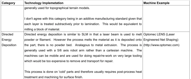
(17) considered that if a part is simple, it should not be manufactured using AM, but rather conventional techniques would be better suited. AM techniques should be seen as complementary to existing manufacturing methods rather than a replacement for them.. ASTM F2792-12a (ASTM, 2012) provides a standardised terminology for AM technologies and defines seven categories as shown in Table 2 along with a brief description of the implementation of the technology and examples of machines using the technology.MakerBot would be used as the baseline for this build.. 7.
(18) Category. Technology Implemetation. Machine Example. Vat Photo-. Stereo Lithography (SLA) – uses an ultra violet (UV) laser to trace the layer geometry Stratasys Viper Si2. polymerisation on to the surface of a vat of resin, selectively hardening the resin. The part then drops (http://www.stratasys.com) down on a build plate into the vat, by the selected layer thickness. A fresh layer of resin is drawn over the top of the part and the process continues. This process requires a significant volume of resin to be kept in the vat for large parts. Digital Light Processing (DLP) – is a relative new-comer, instead of using a laser to Formlabs Form1+ trace the geometry, a complete image of the layer is projected onto the resin surface (http://formlabs.com) from beneath using the same technology as a digital overhead projector.. This. method is usually much faster than SLA and also requires far less resin to be held in the vat as the part is lifted out of the vat as it is built. Material Jetting This method is primarily aimed at the investment casting market. Parts are jetted Stratasys CrownWorx using similar technology to inkjet printing but using wax or resin to built very detailed (http://www.stratasys.com) parts, which can be cast. Objet500 Connex This is currently the only technology capable of producing parts with variable material (http://www.stratasys.com) properties. For example, by mixing resins together in different ratios within a part. Parts can be printed with hard ABS-like plastic in some places and blend or step to Objet was acquired by Stratasys soft rubber like material.. in December 2012 8.
(19) Category. Technology Implemetation. Machine Example. Binder Jetting. This method is similar to material jetting in that a resin is deposited using similar ZCorp ZPrinter 650 technology to inkjet printing. However, the resin is jetted into a powder bed (usually a (http://www.zcorp.com) plaster of paris type material), fusing the powder together. This technology is capable of printing in full colour by mixing resins in exactly the same way as colour inkjet Zcorp was acquired by 3D printing. The parts made tend to be very fragile and as a result are only usually used Systems in January 2012 for form and fit prototyping or display models. Alternative materials include sand for producing casting moulds and cores.. ExOne S-Max Furan (http://www.exone.com). Metal powders can also be used, after post-processing to sinter the metal powder ExOne M-Print and remove the resin, a usable metal part is produced, although not usually fully (http://www.exone.com) dense. Material. Fused Deposition Modeling (FDM), also known as Fused Filament Fabrication (FFF) Stratasys FDM Fortus. Extrusion. is a process using thermoplastic, usually in the form of a filament, heated until molten (http://www.stratasys.com) and then extruded through a fine nozzle.. Powder Bed. Selective Laser Sintering (SLS) and Selective Laser Melting (SLM) are essentially the SLS. Fusion. same process. A laser is used to trace the layer geometry in the same way as SLA but on a powder bed. Materials range from plasitics through to ceramics and even 3D Systems sPro 60 HD metals.. (http://www.3dsystems.com) 9.
(20) Category. Technology Implemetation. Machine Example. The processing of metals requires an inert atmosphere within the build envelope to SLM prevent formation of metal oxides and impurities. Renishaw AM250 The only real difference between SLS and SLM is amount of enegy imparted to the (http://www.renishaw.com) powder by the laser beam. SLS is low power (typically <200W) as a result the particles are only sintered together resulting in porous parts. SLM is much higher power (typically 200-1000W) and imparts sufficient energy to the powder to melt the particles and produce fully dense parts. Electron Beam Melting (EBM) is the latest entrant in the powder bed fusion market, Arcam Q10 claiming better material properties than SLS/SLM due to being processed at high (http:\\www.arcam.com) temperature and in a vacuum. EBM is also generally faster as there are no moving parts. I contrast to SLS/SLM, where galvanometers are used to direct the laser beam (upto 2M/s), EBM uses magnetic fields to direct the electron beam. As a result, the beam can be driven round at much higher speed (upto 8000M/s). This gives EBM the capability of maintaining multiple melt pools. Sheet. This process usually uses sheets of paper but can also be plastic or thin metal Mcor IRIS. Lamination. sheets. Each sheet is cut out to the precise shape of the layer and then laminated to (http://www.mcortechnologies.co the previous one. There is a significant amount of waste from this process. It is m) 10.
(21) Category. Technology Implemetation. Machine Example. generally used for topographical terrain models. I don't agree with this category being in an additive manufacturing standard given that each layer is treated subtractively prior to lamination. This would be equivalent to milling a block of material. Directed. Directed energy deposition is similar to SLM in that a laser beam is used to melt Optomec LENS (Laser. Energy. powder or filament. However the process melts the material as it is deposited onto Engineered Net Shaping). Deposition. the part, there is no powder bed. Analagous to metal extrusion. The process is (http://www.optomec.com) generally used with a 5/6 axis robot arm rather than a cartesian machine.. The. machines can be mobile and are used for doing repair/re-work on very large tooling which would be too expensive to remove and transport for repair. This process is done on 'cold' parts and therefore usually requires post-process heat treatment and machining for surface finish. Table 2: ASTM Additive Manufacturing Technology Catagories. For the purposes of this research, the Material Extrusion category and Fused Deposition Modeling were the focus.. 11.
(22) 2.3 Fused Deposition Modeling (FDM). The FDM process was invented by S. Scott Crump, with the initial patent filed on 30 October 1989 and approved on 9 June 1992 (Crump, 1992). On filing the patent, Crump co-founded Stratasys with his wife Lisa Crump in Eden Prairie, Minnesota (Stratasys). The patent described a method whereby, an object (40) could be created as a digital computer aided design (CAD) model (36).. The model would then. processed by 'layering' software (42), the output of which was then fed into the modeler controller (44).. The modeler controller (44) was responsible for. converting the layers into a physical object (40a) by controlling motors on the X (24), Y (20) and Z (32) axes of a machine as well as controlling the temperature and feed rate of an extruder head (2).. The modeler controller (44) would. maintain the thermoplastic in the extruder melt chamber at a temperature just above the melting point, such that it would solidify almost instantly as it was extruded and cooled.. Figure 1: FDM Machine General Design (Crump, 1992). 12.
(23) Since the initial patent in 1989 there has only been one other patent, filed on 29 May 1997 (Crump, 1999), that has had a significant impact on the design of FDM machines. This patent related to the temperature control of the build volume during and after the build process to prevent 'curling' and delamination caused by thermal stresses within the part. Several different designs for the extruder head were discussed in the patent (Crump, 1992). The most popular design to date has been the implementation of a flexible filament driven into a melt chamber using a motor mounted just above the melt chamber. Early designs used DC motors to drive the filament into the melt chamber. The Stratasys FDM Vantage X that is the subject of this research also uses DC motors in the extruder head. DC motors have significant inertia and as a result, even after stopping the motor, filament would continue to be fed into the melt chamber, creating excess extrusion. Recent designs have largely solved this problem with the use of stepping motors, which allow for far more accurate control of the extruder.. 2.4 The Open-Source Model. The Open-Source (OS) model is not a new concept, the Motor Vehicle Manufacturers Association in the United States (US), came to an agreement on sharing of intelectual property (IP) and patents back in 1911. By the time the US entered the second world war, 607 patents (92 belonging to the Ford Motor Company and 515 others held by other US manufacturers) were being openly shared between US motor manufacturers without exchange of money or lawsuits (Flink, 1977). Open standards were adopted in the 1950's & 60's when the Advanced Research Projects Agency Network (ARPANET) used Request For Comments (RFC's) to develop telecommunication protocols, leading to the development of the Internet in 1969 (Crocker, 2009). 13.
(24) Bulletin Boards (BBS) were used as the early means for developers to share and modify source code and Linus Torvald was one of the first to adopt this process when he began devolpment of the Linux operating system, using comp.os.linux on USENET (Open Source, 2014). Open Source was not used until the Free Software Movement adopted the term following a strategy meeting in January 1998, in Palo Alto, California (Tiemann, Michael, 2006). As a development model, Open Source aims to promote universal access, via free license, to a product's design or blueprint, and universal redistribution of that design or blueprint, including subsequent improvements to it by anyone. There have been numerous licences which have been used to enable freeaccess, starting with the Netscape Public License and later the Mozilla Public License (Netscape Public License, 1998). asymetric with respect to rights.. However, these licenses were. Netscape/Mozilla had the right to modify,. distribute and even close the source on any contributions made, without reciprocal agreements for the contributors, it was therefore considered one to be avoided. The Open Source Initiative published a list of almost 80 OS licenses (Open Source Initiative) approved by their License Review Process. However with so many different licenses, it is difficult to know which ones can or can't be used in conjunction with each other! Although simple in it's concept, the OS model is difficult to implement as is evident by the number of licenses available. There are numerous examples where ideas that were initially developed in an OS model have subsequently been closed, as private individuals or enterprises modified/updated the code for their own commercial benefit. One of the most recent and contraversial was the closing of Makerbot Industries' Replicator design, the bulk of which had been based on OS hardware and software from the RepRap and later, Makerbot communities. Both hardware and software were developed over many years, 14.
(25) with input from countless owner/developers, improving the design.. These. modifications were incorporated into the Replicator and it successors without maintaining open access to the developments.. 2.5 Development of Open-Source FDM Machines. Development of OS 3D Printers began in 2005 at Bath University. The project was started by Dr Adrian Bowyer, a senior lecturer in mechanical engineering. The goal of the project was to develop a machine capable of 'replicating' as much of itself as possible, with the aim of spreading the technology as far and wide, as cheaply as possible. Hence the name Replicating Rapid Prototyper, shortened to RepRap. The first RepRap was release in March 2007 and named 'Darwin' after Charles Darwin, 'the father' of evolutionary theory.. Figure 2: RepRap Darwin (http://en.wikipedia.org/wiki/File:Reprap_Darwin.jpg). 15.
(26) Development continued and in the October 2009, version 2.0 the 'Mendel' was released. The biggest change was a move from a cube design, to a triangular prism. Generation 3, released in August 2010, was named 'Huxley', it was essentially a miniaturised version of Mendel (Gilloz, 2012).. Figure 3: RepRap Mendel (http://www.cnccookbook.com/img/OthersProjects/3DPr inting/reprap.jpg) The RepRap project used the term 'Fused Filament Fabrication' in order to avoid copyright issues with the term 'Fused Deposition Modeling' used by Stratasys however, the principal would have been in breach of the Stratasys patent (Crump, 1992) but this was never challenged, possibly due to the fact that a patent is only binding for 20 years and would have therefore been due to expire in 2009. As of the beginning of this project in 2012, there were in excess of 200 designs either directly or indirectly related to Darwin (Gilloz, 2012).. 16.
(27) Most RepRap designs are open-frame designs. One of the draw-backs of these designs is that they can be susceptible to drafts, which cause un-even cooling of the part. The result can be delamiation of the part where the thermal stress, from the contraction of the plastic as it cools, exceeds the shear stress of the inter-layer bond. Some of the later designs based on the RepRap, such as the MakerBot family (Cupcake CNC, Thing-o-Matic and the Replicators) or the Ultimaker use a 'Boxbot' approach, enclosing the print volume to retain heat and exclude drafts. The Stratasys machine that I will be modifying extends this 'Boxbot' approach by having a fully heated build envelope rather than just the build table as many of the open-source bots do.. Figure 4: MakerBot Replicator (http://www.zahncenternyc.com/wpcontent/uploads/2014/08/MakerBot-Replicator.jpg) The hardware for the RepRap was designed to be simple to construct, using threaded rods for the frame which allowed for accurate adjustment. The corner knuckles were made of plastic and able to be 3D printed to allow it to replicate its own parts. The electronics used were based around the Arduino platform, an open source single board microcontroller with an Atmel 8-Bit AVR at the core. 17.
(28) Arduino was the brain-child of Massimo Banzi, who taught at the Interaction Design Institute Ivrea in Ivrea, Italy (Kushner, 2011).. It was developed in. response to the high cost of the 'BASIC Stamp' used for teaching at the time in 2005. As was the design philosophy for Arduino, the RepRap project used custom add-on boards (shields in Arduino terms) to control the stepper motors for each axis. Arduino was also used as the basis of the design for the extruder controller, but rather than having additonal shields to control the heater and motor control, a board was designed incorporating all of the necessary features. The cross-platform Arduino Integrated Development Environment (IDE) was written in Java and derived from the Processing programming language and Wiring project (Kushner, 2011). Programming in C/C++ with a 'Wiring' wrapper, the IDE allowed the novice programmer to compile and upload to the Arduino hardware with a single button press. Although the RepRap hardware used the Arduino platform as a basis, the RepRap firmware was written in native C++ rather than the Arduino 'sketch' based IDE. It used the GNU AVR-GCC toolchain and AVR-DUDE to upload the initial code to the Arduino via the In-Circuit Serial Programming (ICSP) port. This allowed for faster, more comprehensive control at a lower level, with some registers being set directly rather than through high-level function calls. RepRap used a modified Arduino bootstrap to allow firmware updates to be done over the USB connection. G-code or RS-274-D (Electronic Industries Association, 1969), used to program Computer Numerical Control (CNC) equipment was seen as the most sensible 'language' for controlling the printer. However, directly interpreting the native ascii g-code places a heavy burden on the microcontroller and the serial link from the PC to the printer. As a result, the g-code is transcoded at the computer into a low-level hexadecimal format, Sanguino 3G or S3G (Metts), Sanguino being the particular implementation of the Arduino platform being used. The software used for controlling the RepRap and most 3D printers derived from RepRap is called ReplicatorG. It is also open source and written in Java to 18.
(29) be cross-platform (ReplicatorG).. ReplicatorG is written to work with either. STereoLithography (STL) files or a sub-set of G-code (Bowyer, 2014). The STL file format was developed for 3D Systems, by the Albert Consulting Group, for their stereolithography process (STL, 2014). Surface objects are represented using a triangulated mesh much as finite elements analysis packages currently use. When a CAD model is converted to STL format, the surfaces are represented with triangles, the size of the triangles is determined by the required resolution and the the maximum deviation allowed from the surface. The higher the resolution, the smaller the triangles but the bigger the file. There is a trade-off between the file size/resolution and the capabilities of the machine processing the file, there is no point generating STL files at a resolution higher than the positional step size of the machine. Skeinforge is a 'plug-in' used with ReplicatorG to perform the slicing of STL files and generation of G-code for each individual layer. The power of Skeinforge comes from the fact that it is massively configurable, this is probably also a draw-back as an in-depth knowledge of the configuration settings is needed to produce a really good result. Later versions of ReplicatorG included other open source. slicing. engine. (http://slic3r.org). and. options. like. Miracle. Slic3r. Grue. by by. Alessandro. Ranellucci. Makerbot. Industries. (http://makerbot.github.io/Miracle-Grue). The principle behind the slicing software is essentially simple. A perimeter is generated by joining up all of the points at which the layer cuts each triangle edge. The interior of the model is then 'filled' according to the selected fill pattern and density. The complexity comes from all of the parameters that can be modified relating to the extrusion rate, speed, how much to 'back-off' at the end of a run, where to place support material etc. If an object is to be printed on a 'raft', the slicing engine is also responsible for determining the layout of the raft depenent upon the operator setting for number of layers, distance the raft extends beyond the object perimeter etc. STL as a file format has is limitations. STL files contain no scale information, 19.
(30) units are arbitrary. There is also no colour or material information. Newer formats such as the Additive Manufacturing File (AMF) format, an Extensible Markup Language (XML) based format, developed by ASTM, have been introduced to address some of these issues (ASTM, 2013). Due to past experience with the MakerBot Thing-O-Matic, it was decided that the MakerBot would be used as the baseline for this build.. 20.
(31) 3 Mechanical Design 3.1 Motors The FDM Vantage X uses 3-phase, brushless AC servo motors (ElectroCraft XBR-2910) to drive X, Y and Z axes.. 3.1.1. Servo Motor Theory. AC servo motors are an induction motor. The rotor is made of laminated steel with conductive bars embedded in them, usually copper or aluminium. The conductive bars are short circuited together at the ends, forming a 'squirrel cage'. Laminated steel is used to reduce eddy current losses. The stator is also made of laminated steel. laminates in slots.. Coils are wound around the. The coils are connected to a variable frequency power. supply. When power flows through the windings, a rotating magnetic field is setup. A voltage is induced in the conductive bars which causes a current to flow in them. The resulting electromotive force causes the rotor to accelerate. As the speed of the rotor increases, the voltage induced decreases. As the speed of the rotor approaches that of the rotating field (synchronous speed), the resulting torque reduces to zero. In practice, due to drag and friction forces, the speed of the rotor is always lower than the synchronous speed. The speed of rotation can be calculated based upon the frequency of the supply and the number of pole-pairs on the stator. ωf = 2·π·f/p where : ωf is the synchronous rotating speed in radians/sec f is the supply frequency (Hz) p is the number of pole-pairs. 21.
(32) With the decrease in the cost of solid-state electronic switching devices, control of AC servo motors has become relatively cheap.. In the Stratasys FDM. Vantage X, power for the motors is a regulated 48V, 16.5A DC supply from an Astec MP8-3W-1W-1Q-30 modular power supply. The DC supply is inverted using thyristor or Insulated-Gate Bipolar Transistor (IGBT) switches in a 3phase bridge configuration. By turning on/off the thyristors in sequence, the current can be directed through each of the windings of the motor. Thyristors continue to conduct until the current returns to zero, the frequency controller must electronically force conduction to stop. Cummutation control is generally achieved using hall effect sensors on the back of the motor.. Figure 5: Simplified AC Motor Control. Since the motor tries to match the synchronous speed of the supply, by varying the frequency of the switching, the speed of the motor can be controlled. In the case of the motors used in the Stratasys FDM Vantage X, the control signals are Pulse Width Modulated (PWM) using Advanced Motion Controls B12A6 PWM Servo Amplifiers, providing a variable frequency 3-phase AC motor drive.. 22.
(33) The input to the B12A6 PWM amplifiers is analogue, ±10VDC, from an ACROLOOP ACR8000 in the industrial PC. On its own, an AC motor has only coarse positional control, provided by the commutation hall effect sensors.. However, servo motors are fitted with a. positional encoder attached to the shaft on the back of the motor and used to close the control loop. The encoder can be either absolute or incremental. An absolute rotational encoder gives the position of the shaft regardless of any power cycling. Historically absolute encoders have been optical, providing a position in either Binary Coded Decimal (BCD) or more commonly Gray Coded (GC). The benefit of GC over BCD is that only 1 bit ever changes at a time, whereas BCD changes multiple bits at a time. By changing only a single bit, errors can more easily be detected and corrected.. Modern high resolution. magnetic encoders are now being used for improved reliability.. Decimal. Binary Coded Decimal. Gray Code. 0. 000. 000. 1. 001. 001. 2. 010. 011. 3. 011. 010. 4. 100. 110. 5. 101. 111. 6. 110. 101. 7 111 Table 3: Gray Code vs Binary Coded Decimal. 100. Incremental encoders such as the standard quadrature encoders used on many servo motors provide position relative to a reference point. They require a 'zero' calibration prior to use. They usually have three outputs, A, B and Z or Index. The A and B outputs provide angular position and direction, whilst the Z or Index provides a single pulse per full rotation for example each time 180º is passed on the shaft.. 23.
(34) Figure 6: Quadrature Incremental Encoder Output Waveform (http://sine.ni.com) The ACROLOOP in the industrial PC uses the feedback from the incremental encoders integrated into the XBR-2910 servo motors, giving full closed-loop speed and positional control after an initial 'zero'.. 3.1.2. Stepping Motor Theory. An alternative to servo motors is to use stepping motors. There are essentially two different types of stepping motor, Variable Reluctance (VR) stepping motors and Hybrid stepping motors. Stepping motors are open-loop, there is usually no positional feedback in the form of an encoder. Position is determined by the number of steps moved, giving angular displacement.. Like incremental. encoders, stepping motors require to be 'zeroed' at startup. VR stepping motors have a laminated iron rotor and stator. All of the magnetic flux required to move the stator or hold the stator in place is generated by the stator windings. With a single stack VR motor, the number of rotor and stator teeth determine the step angle generated. Step Angle = 360 / (Poles x Teeth) 24.
(35) In the example shown in Figure 7, there are four rotor teeth and 3 poles (1 pole is made up of 2 teeth, creating a north and a south pole pair), giving a step angle of 30°.. Figure 7: Cross-section through Single-Stack VR Stepping Motor. A three-stack VR stepping motor has the three phases connected to individual poles with an individual stator, see Figure 8 below. Each stator is offset by the step angle such that each phase is excited in sequence causing the shaft with all three stators to rotate. In contrast to the single stack VR, the multi-stack VR has the same number of teeth on the rotor as the stator, when each phase is energised the magnetic flux causes all the teeth on the stator to become aligned with the rotor teeth.. 25.
(36) Figure 8: Cross-section of three-stack variable reluctance stepper motor (http://www.industrial-electronics.com). Hybrid stepping motors have a laminated iron stator. On the rotor, a permanent magnet is mounted between laminated iron end-caps. The magnetic flux runs from the north-pole of the permanent magnet, into the iron end-cap, across to the stator, through the back iron of the stator and back across to the south-pole end-cap, completing the magnetic circuit.. The stator windings are used to. either encourage or discourage the magnetic flux through certainn poles. There are typically eight stator poles, and two windings (A & B).. 26.
(37) Figure 9: 2-Phase Hybrid Stepper Motor (http://www.engineersgarage.com). All of the 'A' windings are connected together and all of the 'B' windings are connected together, however opposing pairs of poles are wound in the opposite direction, so each winding pair has a positive and a negative current direction.. Winding. Current direction. A. Direction of pole magnetic field Radially outward. Radially inward. Positive. 3,7. 1,5. A. Negative. 1,5. 3,7. B. Positive. 4,8. 2,6. B. Negative. 2,6. 4,8. Table 4: Magnetic Field Direction in a 2-Pole Hybrid Stepper Motor. The step length of a hybrid motor is determined by the number of teeth on the rotor. A full excitation cycle (A+, B+, A-, B- for clockwise or A+, B-, A-, B+ for anti-clockwise) produces 4 steps, and since the next step requires the next tooth to be in the same place as the first, 4 steps equates to 1 tooth pitch. So, from the above is can be shown that the step length can be calculated using the following: 27.
(38) Step Angle = 360 / 4 p Where: p = number of teeth on the stator A common step length for a hybrid motor is 1.8º, by transposing the above, p = (360 / 1.8) / 4 = 50 teeth. Current open source 3D printers all use stepping motors for X, Y and Z axes, so rather than designing an interface to convert the stepping motor signals to servo motor signals, it was decided that the servo motors should be changed to stepping motors. The OEM motors were identified as ElectroCraft XBR-2910, NEMA34 Brushless AC Servo Motors with integrated Encoders.. Parameter. Value. Torque Constant (Kt). 1.8 in-lbs/A. Voltage Constant (Ke). 19.9 – 23.1 V/kRPM. Rated Voltage. 230 V. Continuous Speed (no load). 6000 rpm. Peak Torque. 18.5 in-lbs / 2.1 Nm. Continuous Torque. 6.1 in-lbs / 0.7 Nm. Inductance. 5.8mH. Encoder Count. 2000 ppr. Encoder Voltage. 5 Vdc. Encoder Current. 225 mA. Table 5: XBR-2910 Specifications. A set of 3 motors, with matching micro-stepping drives and power supplies, were sourced on Ebay.com from the Longs Motor Company in China.. 28.
(39) Parameter. Value. Part Number. 34HS1456. Step Angle. 1.8º. Current. 5.6A/phase. Resistance. 0.55Ω/phase. Inductance. 5.5mH/phase. Holding Torque. 1232 oz-in / 8.7Nm. Rotor Inertia. 2700g-cm2. Weight. 3.8Kg. Length. 118mm. Table 6: Longs 34HS1456 Stepping Motor Specifications. Higher torque rated stepping motors were selected as stepping motors not having any positional feedback must be run well below their rated capacity in order to minimise the risk of missed steps due to acceleration. The motors selected are 1232 oz-in or 8.7 Nm, 5.6A. The micro-stepping drives are DM860A, 24-80VDC up to 8.0A/phase and capable of 256 pulses/step, giving up to 51200 pulses/revolution with a 1.8º stepping motor (200 steps/revolution).. However, for the purposes of this. project, the MakerBot Thing-O-Matic is designed around 1/8 steps, so a setting of 1600 pulses/revolution was selected on the dip switches. The micro stepping drives and power supplies were installed in the bottom of the machine after removing the redundant Astec MP8 power supply. As there was an individual power supply and drive per axis, each was put on a separate phase to help balance the electrical loads. The existing servo motors were unbolted, but before the replacement motors could be fitted to the printer, the pulleys had to be transferred from the the motor spindles. On removing the pulleys, it was discovered that the shaft diameters were different. The original motors had a shaft diameter of 1/2”, while the new stepping motors had a shaft diameter of 14mm. There was sufficient shoulder on the pulleys to be able to hold them in a lathe chuck and ream the shaft hole 29.
(40) to 14mm whilst retaining sufficient material for the keyed shaft.. 3.2 Front Panel Controller. The Stratasys FDM Vantage X Front Panel Controller (FPC) used a 4x40 LCD display along with a numeric keypad and a number of navigation buttons. A large green illuminated push-button and smaller red push-button start and stop the machine.. Figure 10: Stratasys FDM Vantage X Front Panel Controller. There was a single 9-way D-type connection to the FPC. The start/stop buttons were connected through the D-type to the Power Supply PCB. The start button was normally-open, while the stop button was normally-closed. The remaining connections on the D-type were a 12Vdc supply from the industrial PC and an RS-232 serial connection to the industrial PC. 30.
(41) The initial plan was to re-use the FPC so it was necessary to reverse engineer the serial interface to the industrial PC. Using a pair of RS-232 to USB adapter cables, the TX and RX lines were monitored using a terminal client. Initial attempts using HyperTerm were unsuccessful as HyperTerm was not capable of properly decoding ascii control characters like 'Escape' (ESC). Realterm was used instead as it was capable of capturing the data in hexadecimal format. This allowed full capture and decoding of all of the messages between the FPC and the PC. The transmit pin was connected to the receive pin on adapter 1 and the receive pin was connected to the receive pin on adapter 2 as shown below.. Figure 11: Message Snooping using Dick Smith Electronic RS-232 to USB Adapters. Table 7 shows the serial output codes used to represent each button on the FPC.. 31.
(42) Button. ASCII. HEX. Menu. “M”. 0x4D. Up Arrow. “+”. 0x2B. Down Arrow. “-”. 0x2D. Light. “L”. 0x4C. Pause. “P”. 0x50. Help. “?”. 0x3F. Enter. CR. 0x0A. Delete. DEL. 0x7F. Escape. ESC. 0x1B. .. “.”. 0x2E. 0-9. “0”-”9”. 0x30 - 0x39. Table 7: Serial Output Data from FPC. An example of the format for sending data to the FPC is shown below. [0x1B] [0x5B] [0x30][0x3B][0x37][0x48][0x4A] Byte 1 – 0x1B, ASCII ESC Byte 2 – 0x5B, ASCII [ Byte 3 – The row number (0:3), 0x30 – 0x33, ASCII 0-3 Byte 4 – 0x3B, ASCII ; Byte 5 – The column number (0:39), 0x30 – 0x39, ASCII 0-9 Where the column number is greater than 9, an extra byte is sent. Byte 6/7 - 0x48, ASCII H Byte 7/8 – The ASCII character to be displayed in HEX, e.g. 0x4A, ASCII J As can be seen from the example above, the overhead for sending messages to the FPC was significant. It was determined that the added complication of the changes to the hardware and firmware to handle the serial interface for the FPC was unwarranted. It was therefore decided that the FPC should be redesigned using the physical form of the original panel but the interface and basic button structure from the 32.
(43) MakerBot design. The replacement FPC was designed in Solidworks, re-using the 40x4 LCD screen size but using a button layout more suited to the MakerBot design. The SD card interface was also moved to the FPC to allow for easy access. The panel and buttons were then 3D-printed in Nylon at Massey University, Albany on a TPM3000 Selective Laser Sintering machine. The replacement FPC is shown in Figure 12.. Figure 12: Replacement FPC. 3.3 Extruder Head Solenoid. During testing, due to a design error, the solenoid used for selecting between the two extruders overheated and burned out. When approached with regard to replacing the solenoid, Tasman Machinery would only quote for a complete replacement extruder head at a cost of $20,000. The damaged solenoid was removed from the machine and OEM markings (LISK S-2458-48) found, indicating the device was made by G.W. Lisk in the United States. Lisk were 33.
(44) contacted and supplied a quote, by email, to replace the solenoid at a cost of $900 USD + shipping. Lisk supplied a specification sheet (G. W. Lisk Company, 2011) for the device and it was decided that the most cost effective and quickest solution to the problem was to repair the original solenoid. Using a hydraulic press in the DTA workshop, the coil was pushed out of the housing. The coil was taken to Transformer Specialties in Kumeu and re-wound by hand for $345 and returned the following day. In the process of removing the coil, the housing was damaged beyond repair, so while the coil was being rewound, a new housing was machined in the DTA workshop using a lathe. Once the coil was returned, the unit was reassembled and crimped back together. The cause of the overheating solenoid was found and is discussed further in the Chapter 4 – Electrical Design. 3.4 Other Hardware Modifications. Other modifications included the removal of the Canister Controllers from the front of the machine. This was to allow the use of alternate materials, not contained in canisters but loaded onto drums. There was a small compressor and associated receiver and pressure regulations devices which were no longer required. These were also removed. In the base of the machine, a large UPS was located, that provided backup power to the industrial PC. This was unserviceable, so was removed along with the industrial PC which was no longer required. The space left from removing the UPS was used to house the power supplies for the individual axis stepping motor drives. The cover over this was modified, reducing it's width, to allow a smaller UPS (Blazer 800, acquired from TradeMe) to be fitted along side. This was used to provide backup power to the micro-controllers. The OEM printed circuit boards (PCB's) were also removed and replaced with new hardware, to be discussed further in Chapter 4 – Electrical Design. 34.
(45) 4 Electrical Design The electrical design was split into three main components, the Power Supply, the Extruder Controllers and the Motherboard.. The design for each is. discussed further below, with complete design files (including gerber files for PCB manufacture) contained in Appendix A (See attached CD-ROM). 4.1 Power Supply The OEM power supply was a delta configuration with a working voltage of 230v phase-phase. However, the standard 3 phase voltage in New Zealand is 230v phase-neutral or 415v phase-phase. As a result, when the machine was originally delivered, it utilised a heavy duty transformer on a trolley for converting the New Zealand supply voltage to a suitable level. A 4-core cable was used to connect the 3 phases and earth to the transformer and then, from the transformer to a gland on the back of the machine. Inside the machine, the 3 phases were connected to terminal blocks and then to a 3-phase circuitbreaker.. The output of the circuit-breaker was connected to a filter bolted. directly to the side of the machine housing. The Power Supply PCB was connected directly to the output of the filter by studs with nuts clamping either side of the PCB.. 35.
(46) Figure 13: OEM Power Supply PCB. Phase A-B was connected off-board, via part of JP3, to the main power switch on the back of the machine. This connected power to the primary side of transformer T1. The secondary side of T1 was connected to a bridge rectifier (D10) and regulated DC power supplies (U20 and U21) for the PIC16F877 micro-controller (U9). The PIC supplied a control signal to U1 (Solid State Relay Crydom D2425), switching phase A-B to the UPS and the vacuum pump on the remainder of JP3. The UPS supplied power to JP12, and back out to the industrial PC. JP12 was connected to the primary side of transformer T2. The secondary side of T2 supplied a bridge rectifier (D12), which was connected to the same power rails as D10. Opto-coupled outputs provided an indication to the PIC if the supplies were on. The incoming power from the UPS was connected to U22, U5, K1 and K2, which control the AIR, LIGHTS, HEAD and OVEN circuits respectively on JP5 all driven by the PIC either via the buffer U15 or transistor driver circuits for the relays K1 and K2. 36.
(47) The PIC controls a DC signal to JP2, which is connected to the off-board contactor located underneath next to the incoming power filter. Phases A, B and C are connected from the filter to JP8. JP8 connects to the input side of the off-board contactor, with the output side of the contactor connecting back on to the PS at JP15 as L1, L2 and L3. Three solid state relays (U2, 3 and 4) controlled power to the heater elements A, B and C. Heater A was connected to phases L1 and L2, Heater B was connected to phases L2 and L3 and Heater C was connected to phases L1 and L3. The control signal for the relays was connected to JP18 which in turn was connected to the I/O Control PCB. L1, L2 and L3 were fused, via F1, F2 and F3. L1-L2 was connected via JP6 to the four exhaust fans located in the top of the machine. L2-L3 was connected via JP1 to an external power supply (Astec MP8-3W-1W-1Q-30) which provided 48Vdc and 24Vdc to the I/O Control PCB. L1-L3 was connected to solid state relays U6, U7 and U8. U6 controlled power to the EXTRA circuit (connected to the compressor) on JP7. U7 controlled power to the TIP circuit on JP7. U8 controlled power to the VENT circuit on JP7. U6, U7 and U8 were driven from the PIC, through buffers (U15). L1-L3 was also connected via JP4 to an off-board transformer (located underneath, with the contactor and power supply filter) the output from the transformer was connected back to JP4 and supplies two bridge rectifiers (D6 and D7).. The outputs of the rectifiers were fused through F4 and F5. respectively and connected to JP18, providing High Voltage (150V) DC supplies to the I/O Control PCB. The PIC also provided an RS232 serial connection via U12 to the industrial PC on JP16 and two RS485 serial connections via U10 and U11 to the I/O Control PCB on JP18. With the opportunity to re-design the power supply, it was decided to convert 37.
(48) the machine to a 'star' configuration, meaning that it could be plugged directly into a standard New Zealand 3-phase supply.. The change to a 'star'. configuration required a change of connector and cable from 4-core (3P&E) to 5-core (3P,N&E). Internally, it required an additional terminal block to connect the neutral to the filter. The PCB also had to be re-designed to switch phase-neutral rather than phasephase. To save money and given that it was not planned to re-use the power supply PCB, it was stripped to re-use the parts, saving a significant cost in components (mainly connectors and solid-state relays SSR's). Initially the plan was to make the replacement PCB the same foot-print as the original. However, when the cost of manufacturing the board was investigated, it was prohibitively expensive.. Accordingly, it was decided that the power. supply PCB be split into two parts, a Power Supply Board and a Power Supply Control Board. This enabled both boards to be manufactured using the LPKF PCB mill at DTA. The design philosophy used was essentially the same as the OEM, the incoming supply from the filter was connected to the contactor.. L3 was. connected to the main switch on the back panel, controlling power to the Power Supply Control Board, which in turn was used to switched using a Crydom MCX240D5 solid-state relay (SRR) to power the UPS and a small Point of Load (PoL) 24VDC power supply for the contactor. The signal for the contactor was from the Power Supply Control Board and provided the gate voltage to an FET to switch the contactor. Power supplies for the stepping motor drivers were taken from the fused side of the contactor return side as shown in Figure 2. The heater loads were distributed across the 3 phases and also switched using Crydom D2425 SSR's as shown in Figure 3.. The remaining loads were. distributed as evenly as possible to minimise the neutral current flowing. See Table 1 and Figures 4 and 5 for High Voltage DC (HVDC) rectification and Auxilliary Power Control respectively.. 38.
(49) Figure 14: Incoming Supply Distribution. Figure 15: Heater Control. 39.
(50) Phase. Load. Power. L1. Heater A. 1.8kW. X-Axis Stepper PSU. 350W. Other Ancillaries. ~400W. Heater B. 1.8kW. Y-Axis Stepper PSU. 350W. HVDC. ~900W. Heater C. 1.8kW. Z-Axis Stepper PSU. 350W. L2. L3. UPS + 24VDC Table 8: 3-Phase Power Supply Loading. ~400W. Figure 16: High Voltage DC Rectifier. The two HVDC supplies for the extruder head were developed from the secondary coils of a power transformer enclosed in the bottom of the machine. The outputs were rectified using GBU806-HB bridge rectifiers and smoothing capacitors. Each output was fused and an indicator LED connected using a high power resistor as shown in Figure 16.. 40.
(51) Figure 17 shows how the remaining Auxilliary loads were switched using Crydom MCX240D5 SSR's along with indicator LED's.. Figure 17: Auxilliary Power Control. The Power Supply Board was drawn up in DesignSpark PCB and a PCB generated, see Figures 18 and 19.. 41 Figure 18: Power Supply Board - Top Copper.
(52) Figure 19: Power Supply Board - Bottom Copper. A fault was found with this design during testing. Switching the 24V to the contactor would not work. After some investigation, it was discovered that using a 5V control signal to high-side switch the 24V would not work as there was insufficient potential difference across the gate to switch the device on. The PCB was modified to switch the 24V to the contactor on the low-side.. Figure 20: Low-Side Switching Modification 42.
(53) The digital control board was designed around an Arduino Mega. Although an Arduino Uno would have satisfied the number of I/O's required, the initial plan call for at least three hardware UART's, RS-232 port to communicate with the Web Server, an RS-232 port to communicate with the UPS and a logic level serial port to connect directly to the Motherboard. The Arduino was powered from a redundant 12V supply, generated by a pair of Myrra 47154 regulated 12V PoL power bricks. The primary power supply was connected to L3 from the Power Supply Board and the secondary was connected to the UPS return from the Power Supply Board. The outputs of the two power supllies were tied together through a pair of 1N4001 rectifier diodes. The output of each power supply was connected to the input of a 4N35 optoisolator. The output side of the opto-isolator was connected to the Arduino and also an LED to indicated the presence of power on each as shown in Figure 21.. Figure 21: Arduino Mega Redundant Power Supply. Two additional Myrra 47154 PoL power bricks were used in the same configuration as shown in Figure 21, for monitoring the L1 and L2 from the Power Supply Board.. This allowed the Arduino Mega to determine if all 3. 43.
(54) phases were connected and healthy. Initial testing of the UPS was done using the USB port connected to a PC running. WinPower,. downloaded. download.com/winpower/windows.htm.. from. http://www.ups-software-. This was successful, however, when. re-configured to use the COM port WinPower was unable to communicate with the. UPS.. Using. Google. (https://www.google.co.nz/search?. q=blazer+UPS+protocol) it was determined that the protocol used by the Blazer UPS was the Megatec/Q1 protocol (Chiou, 1996). According to the protocol specification, the serial connection to the UPS had to not only provide a comms link, but also supply power to the UPS serial interface board. For testing, power was connected directly to pin 7. Although power was being provided to the serial interface board, no communications could be achieved. After further investigation it was decided to open up the UPS to verify that the serial interface was indeed implemented. On opening the UPS, it was discovered that a diode (D029) was missing from serial interface board, see Figure 22. A 1N4148 diode was fitted to the board and the board re-fitted to the UPS and serial comms was restored.. Figure 22: Serial Interface Board in UPS 44.
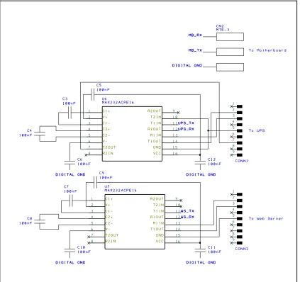
(55) As discussed above, the initial plan was to have three hardware UART's for communications as shown in Figure 23.. Figure 23: Serial Communications. To implement to UPS serial port, T2IN was tied to GND, resulting in 10Vdc at T2OUT. This was connected to pin 7, to provide power for the UPS serial interface. During firmware development, discussed further in Chapter 5 – Firmware Design, it was decided that implementing another serial UART on the Motherboard was going to be problematic.. It was therefore decided that a. better solution to using a logic level UART would be to use the logic level UART 45.
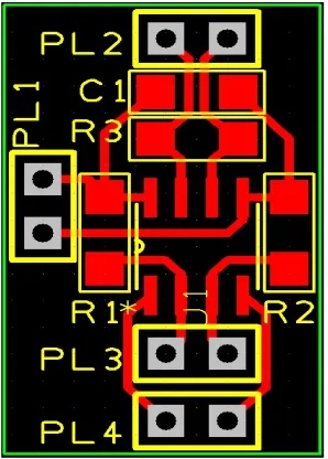
(56) to drive an RS-485 interface (see Figure 12) to communicate with the Motherboard using the existing RS-485 bus. This required two extra pins to control the TX and RX enable pins however, this was not an issue as the Arduino Mega had more than enough spare I/O's to accommodate the change.. Figure 24: RS-485 Serial Interface. The small board was manufactured single sided (See Figure 25) and attached underneath the Arduino Mega.. 46.
(57) Figure 25: RS-485 Interface PCB. It was also decided at this point that the web server would not be used and therefore this RS-232 UART would no longer be required. Given that the Power Supply Board was used for controlling the oven heater SSR's, it made sense for the Power Supply Control Board to monitor the temperature of the oven and provide the control signal to the Power Supply Board. The plan was to use the same thermocouple interface as used on the MakerBot Extruder Controller v3.6, however when attempting to source the MAX6675 thermocouple I/C, it was discovered that the device was no longer being. manufactured.. However,. (http://www.maximintegrated.com). the. Maxim. recommended. the. Integrated. website. MAX31855. (Maxim. Integrated, 2012) as a pin-pin replacement. The MAX31855, an I 2C cold juntion compensated thermocouple interface was only available in a 'K' type from local suppliers, however, the existing thermocouple in the oven was an E-type thermocouple.. The MAX31855-E device was sourced from the Maxim. Integrated website as samples. A total of three devices were requested, one for the oven and one for each extruder.. Unfortunately, the matching E-Type. thermocouple connectors (CN1 in Figure 26) could not be sourced locally and had to be ordered in from Omega in the UK.. 47.
(58) Figure 26: MAX31855 Thermocouple Interface. The Power Supply Control Board was also responsible for the contactor control signal. It was decided that it should be possible to shut off the contactor in an emergency, without having to rely on the Arduino.. The E-Stop was. implemented using the existing 'normally closed' button on the FPC and also a thermal cut-out connected to the top of the oven. A pair of relays, one normally open the other normally closed, were used, to enable control of the contactor by the Arduino with the E-Stops in series, such that if any one of the controls could open the contactor, isolating the 3 phase from the rest of the machine as shown in Figure 27.. 48.
(59) Figure 27: E-Stop Protected Contactor Control. It was also decided that the Arduino should have a method of checking to see if the DC power supplies were on-line. Four DC supplies were monitored, the 24V supply to the Motherboard and Extruders and the three 60V supplies to the Stepping Motor Drives. These supplies were monitored using opto-isolators in the same manner as the outputs from the PoL bricks used to monitor the UPS, L1, L2 and L3.. 49.
(60) Figure 28: DC Power Rail Monitoring. All of these interfaces were tied together using an Arduino Mega 2560 as described earlier in this chapter.. Figure 29: Arduino Mega 2560 Power Supply Controller 50.
Figure


+7




Related documents
The objective of this study was to evaluate the knowledge and perceptions on family planning and emergency contraception of the first year students of an international medical school
It was decided that with the presence of such significant red flag signs that she should undergo advanced imaging, in this case an MRI, that revealed an underlying malignancy, which
Using a stepped- wedge trial design to randomly assign HIV care clinics to scaled initiation of PrEP integrated into HIV care for cou- ples, the RE-AIM (Reach, Effectiveness,
19% serve a county. Fourteen per cent of the centers provide service for adjoining states in addition to the states in which they are located; usually these adjoining states have
The solution that we propose to the issue of Roaming in wireless community networks is done in two parts: (1) the proposal of a Protocol (RRP) enabling an LDAP server to behave as
Assessing the Impact of Biodiversity Conservation in the Management of Maize Stalk Borer (Busseola f
Field experiments were conducted at Ebonyi State University Research Farm during 2009 and 2010 farming seasons to evaluate the effect of intercropping maize with
In the testing phase of this research uses two testing, testing the first testing the strength of the encryption process after ciphertext randomness using
