UNIVERSITI TEKNIKAL MALAYSIA MELAKA
Development of an Electronic Educational Quiz Kit that Test Student
Knowledge on Translating Timing Diagram to the PLC Ladder
Diagram
(PLC Education Quiz Kit)
This report is submitted in accordance with the requirement of the Universiti Teknikal Malaysia Melaka (UTeM) for the Bachelor of Electronic Engineering Technology
(Industrial Electronics) with Honours.
by
NIK MUHAMAD FIRDAUS BIN ZAIMI
B071410207
940219-03-5743
BORANG PENGESAHAN STATUS LAPORAN PROJEK SARJANA MUDA
TAJUK: Development of an Electronic Educational Quiz Kit that Test Student Knowledge on Translating Timing Diagram to the PLC Ladder Diagram SESI PENGAJIAN: 2017/18 Semester 1
Saya Nik Muhamad Firdaus bin Zaimi
mengaku membenarkan Laporan PSM ini disimpan di Perpustakaan Universiti Teknikal Malaysia Melaka (UTeM) dengan syarat-syarat kegunaan seperti berikut:
1.0 Laporan PSM adalah hak milik Universiti Teknikal Malaysia Melaka dan penulis. 2.0 Perpustakaan Universiti Teknikal Malaysia Melaka dibenarkan membuat salinan untuk
tujuan pengajian sahaja dengan izin penulis.
3.0 Perpustakaan dibenarkan membuat salinan laporan PSM ini sebagai bahan pertukaran antara institusi pengajian tinggi.
4.0 **Sila tandakan ( )
SULIT
TERHAD
TIDAK TERHAD
(Mengandungi maklumat yang berdarjah keselamatan atau kepentingan Malaysia sebagaimana yang termaktub dalam AKTA RAHSIA RASMI 1972)
UNIVERSITI TEKNIKAL MALAYSIA MELAKA
(Mengandungi maklumat TERHAD yang telah ditentukan oleh organisasi/badan di mana penyelidikan dijalankan)
(TANDATANGAN PENULIS) Alamat Tetap:
Lot 488 Kampung Sungai Hala, 18500 Machang, Kelantan
Tarikh: _______________________
Disahkan oleh:
(TANDATANGAN PENYELIA) Cop Rasmi:
** Jika Laporan PSM ini SULIT atau TERHAD, sila lampirkan surat daripada pihak berkuasa/organisasi berkenaan dengan menyatakan sekali sebab dan tempoh laporan PSM ini perlu dikelaskan sebagai SULIT atau TERHAD.
ii
DECLARATION
I hereby, declared this report entitled “Development of an Electronic Educational Quiz Kit that Test Student Knowledge on Translating Timing Diagram to the PLC Ladder Diagram” is the results of my own research except as cited in references.
Signature :
Author‟s Name : NIK MUHAMAD FIRDAUS BIN ZAIMI
iii
APPROVAL
This report is submitted to the Faculty of Engineering Technology of UTeM as a partial fulfillment of the requirements for the degree of Bachelor of Electronic Engineering Technology (Industrial Electronic) with Honours. The member of the supervisory is as follow:
………
iv
ABSTRAK
v
ABSTRACT
vi
DEDICATION
vii
ACKNOWLEDGEMENT
viii
TABLE OF CONTENTS
Declaration ii
Approval iii
Abstrak iv
Abstract v
Dedication vi
Acknowledgement vii
CHAPTER 1 : INTRODUCTION 1
1.0 Introduction 1
1.1 Background Study 1
1.2 Problem Statement 2
1.3 Objectives 4
1.4 Scope of Work 5
1.5 Project Constribution 6
CHAPTER 2 : LITERATURE REVIEW
72.0 Introduction 7
2.1 Hardware Used 7
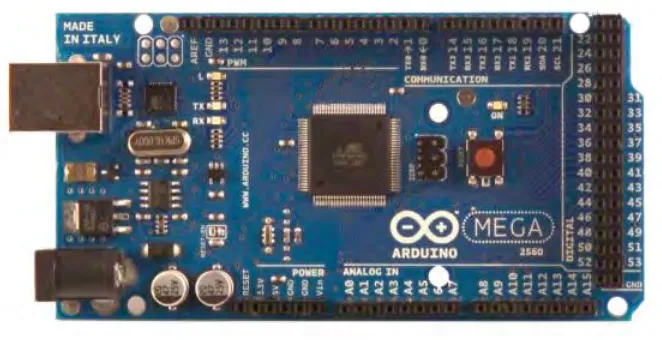
2.1.1 Arduino Mega 2560 7
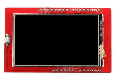
2.1.2 Thin-film-transistor Liquid-crystal Display (TFT LCD) 9
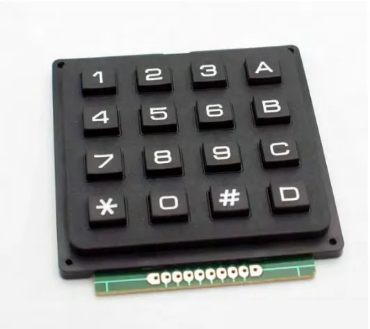
2.1.3 4x4 Matrix Keypad 9
2.1.4 Logic Gate IC 10
ix
2.2.1 Programmable Logic Control S7-300 11
2.2.2 PLC-200 Trainer Kit 12
2.2.3 PLC Training Kit Set and PLC Application Modules 13
2.2.4 Modular PLC Training Kit 14
2.2.5 PLC Training Kit 15
CHAPTER3 : METHODOLOGY
17
3.0 Introduction 17
3.1 Flow of the Project 17
3.2 Project Layout 20
3.3 Block Diagram 21
3.4 Flowchart of Program 22
3.5 Estimated Cost 27
3.6 Circuit Simulation 28
CHAPTER 4 : RESULTS AND DISCUSSION
31
4.0 Introduction 30
4.1 Comparison between expected results with the actual result base on scenario 30
4.2 Result Analysis based on Survey Question 36
CHAPTER 5 : CONCLUSION AND RECOMMENDATION 48
5.1 Conclusion 47
x
REFERENCES
50
xi
LIST OF FIGURES
2.1 Image of Arduino Mega 2560 8
2.2 Image of TFT LCD 9
2.3 Image of 4x4 Matrix Keypad 10
2.4 Image of Logic Gate IC 11
2.5 Image of S7-300 Trainer Kit 12
2.6 Image of PLC-200 Trainer kit 13
2.7 Image of PLC Training Kit 14
2.8 Image of Modular PLC Trainer Kit 15
2.9 Image PLC Training Kit 16
3.1 Flowchart of the Final Years Project (FYP 1 and FYP 2) 19
3.3 Block Diagram of the Project Error! Bookmark not defined. 3.4 Flowchart of program 26
3.5 Circuit Simulation 28
4.1 The whole kit during main menu 31
4.2 TFT LCD display main menu 31
4.3 TFT display question 32
4.4 The connection of the equivalent ladder diagram for that question 32
4.5 The TFT LCD display the output timing diagram for the true connection of equivalent ladder diagram 34
xii
4.7 TFT LCD display the question 34
4.8 The wrong connection of the equivalent ladder diagram 34
4.9 TFT LCD display the answer of the wrong connection of the equivalent ladder diagram 35
4.10 TFT LCD display „you are wrong‟ and your score 35
4.11 The connection of the equivalent ladder diagram that used interner relay 35
4.12 TFT LCD the output timing diagram for the connection of equivalent ladder diagram that using internal relay 37
4.13 Respond for question 1 37
4.14 Respond for question 2 38
4.15 Respond for question 3 39
4.16 Respond for question 4 40
4.17 Respond for question 5 41
4.18 Respond for question 6 42
4.19 Respond for question 7 43
4.20 Respond for question 8 44
4.21 Respond for question 9 45
xiii
LIST OF TABLES
3.5 Estimating cost for the project 27
1
CHAPTER 1
INTRODUCTION
1.0 Introduction
This chapter aim on creating the frame work of this project. It includes all the requirements that need to be achieving at the end of the associated project. The project background will be briefly described. Therefore, the structure of the whole project can be precisely visualized.
1.1 Background Study
According to Ashaari( 1999 )Educational kit defined as “tools used in teaching which should not be limited to devices that are commonly used as a blackboard, pictures and all hardware and software for teaching”. Development of the educational kit is to help student more understand practically about what they learn. It also wants to help student more familiar with the connection of the component.
2 makes a programmer easy to arrange the flow of the process. When using PLC also make some programmer easy to trouble shoot the problem of the process. This programmable logic control had been teach in the subject control principle (BETE 2364) for the engineering technology and subject control principle and system (BENE 3223) for the pure engineering at the University Teknikal Malaysia Melaka. It been teach in the lecture session for the general theory, specific to the calculation in the tutorial session and in the lab session student will learn how to make some program of PLC and hand on.
PLC educational quiz kit is a trainer kit that tests the student understanding about converting timing diagram into the equivalent ladder diagram. This will be done by having the educational kit to display question in term of mnemonic code. Then the student required doing the equivalent ladder diagram connection on the educational board. Once the connection is done, this educational kit will check whether the connection is correct or not.
1.2 Problem Statement
At University Teknikal Malaysia Melaka (UTeM), this programmable logic control (PLC) had been taugh in the subject control principle (BETE 2364) for the engineering technology and subject control principle and system (BENE 3223) for the pure engineering. It been teach in the lecture session for the general theory, specific to the calculation in the tutorial session and in the lab session student will learn how to make some program of PLC and hand on.
3 lesson session is student will be boring. It also makes the students feel sleepy. Moreover, just a few students can stay focus until the end of the lesson.
During the tutorial session, it will do in the small class room. Lecturer will prepare some question for students. Students need to answer that question. At the end of the class, lecturer will pick some question to discuss in the class. The weakness of this tutorial is students just understand about the theoretical. The question provided also just a little bit and it does not interesting. It cannot attract the interest of the student to learn. Moreover, just a few students do the tutorial question.
4
1.3 Objectives
The objectives for this project are:
1. To design a proof of concept an educational quiz kit that tests the students understanding of PLC‟s.
The design of educational quiz kit consists of 2 parts. First part is external hardware design. This part is about designing the casing of the educational quiz kit. The second part is internal hardware design which consists of electronic circuit and software design which consist of source code.
2. To build the proof of concept of the compatible that is 8cm x 10 cm and low cost that is less than RM300 educational kit that using Arduino Mega as the controller.
The external casing will be the plastic. It is because it easy to cut. It also cheap compare to the other material. So the cost of the project can be reduced. The microcontroller is Arduino Mega 2560. It is because Arduino Mega 2560 more cheaply compare to other microcontroller such as raspberry pie.
3. To verify the the functionality of the educational kit by performing a set of system testing which will be based on a checklist.
This will be done by testing one by one of the connection port at the kit and see the output results that is follow the expected output or not.
5
1.4 Scope of Work
In designing the educational kit, this project had limited to certain criteria. The criteria are number of difficulty, number of input and output, number of questions and method of inserting the questions. First, the amount of the questions. In this educational kit have six questions. It limited to six questions because this educational quiz kit still in testing phase. Third is limitation number of input and output. The number of input is limited to three and number of output also limited to three. It is because this just covered a few basic instructions in the ladder diagram. It do not cover for the latching, counter and the other advance instruction in the CX Programmer. This project used Arduino Mega 2560 as it microcontroller. It is because this Arduino Mega 2560 is more cheap compare to raspberry pie and other microcontroller. It also used thin-film-resistor liquid-crystal display (TFT LCD) to display input and output. It is because TFT LCD can display apart of word such as graph. This project also just used a few button of the keypad which is button 1, 2,A and B. It is because this project used keypad just for to select either want to do simulation or question, to check the answer of the connection and to continue to the next question at quiz part.
6 Malaysia Melaka. I make some survey with the Engineering Technology students. It has limited to 50 of students. It is because students busy with their own work and responsibility. Moreover, I do not have enough time to make a survey more than that. It also do not has the return button because the digital pins for Arduino is full. The return button need to used interupt. The interupt needs to use certain digital pins such as digital pin 2,3,8 and 9.
1.5 Project Constribution
7
CHAPTER 2
LITERATURE REVIEW
2.0 Introduction
This chapter consists of two section where is the first section explain about the hardware used in this project and the second part is explain about the previous project that related to this project.
2.1 Hardware Used
This part will explain about all the research of hardware that used in this PLC Trainer kit which is Arduino Mega 2560, thin-film-transistor liquid-crystal display (TFT LCD), Logic Gate IC and 4x4 matrix keypad.
2.1.1 Arduino Mega 2560
8 contains everything needed to support the microcontroller. This Arduino Mega 2560 used 5V to operate the system. This Arduino Mega 2560 is used in PLC quiz kit project as a microcontroller. It was the brain of this project. The operation flow of this project will be control by this microcontroller. It also used as a port connection for power supply to powered the whole component in this project. Figure 2.1 below show the image of Arduino Mega 2560.
9
2.1.2 Thin-film-transistor Liquid-crystal Display (TFT LCD)
[image:23.612.228.425.277.406.2]According to B.Christhoper n.d.(2010) Thin-film-transistor liquid-crystal display (TFT LCD) is an lcd with the high resolution screen display. It also a touch screen lcd. It consists of 28 pin as port of the connection. It powered by 5V of power supply. This thin-film-transistor liquid-crystal display (TFT LCD) is used in this project as output display. It will display the level of difficulty, the question of this quiz kit and the answer of the question. It also acts as an instruction for this quiz kit. Figure 2.2 below show the image of TFT LCD.
Figure 2.2 : Image of TFT LCD(B.Christhoper n.d.2010)
2.1.3 4x4 Matrix Keypad
10
[image:24.612.195.461.127.364.2]In this PLC educational quiz kit, keypad was used as an input. The user will use keypad to select the level of the difficulty. Keypad also used to check the answer of the question. Figure 2.3 below show the image of 4x4 matrix keypad.
Figure 2.3 : Image of 4x4 Matrix Keypad (B.Christhoper n.d.2010)
2.1.4 Logic Gate IC
According to B.George (2000) Logic gate IC is a component that deals with the true and false instead of number. In electronic circuit, the true and false can be defined by the present of the voltage in the circuit. True will be defined when it detect the present of voltage and false will be defined when it no voltage. It has many type of logic gate IC such as AND gate IC, OR gate IC and NOT gate IC.