A Smart Transformer-Rectifier Unit for the More
Electric Aircraft
Giampaolo Buticchi, Chris Gerada
University of Nottingham Ningbo ChinaChina,
Email: [email protected]
Young Jong Ko, Marco Liserre
University of KielGermany
Email: Email: yoko, [email protected]
Abstract—In the framework of the More Electric Aircraft (MEA), an efficient and flexible power distribution system is of paramount importance. Considering the presence of both AC and DC loads at multiple voltage levels, the distribution system of the most modern aircrafts is intrinsically hybrid. In this scenario, the different buses are connected by AC/DC converters. The simplest approach is to use a Transformer-Rectifier Unit (TRU) based on a low-frequency transformer followed by passive rectifiers to perform the AC/DC conversion. This solution, however, is intrinsically uni-directional, introduces current harmonics in the AC side and can have a considerable size. This paper proposes the use of a Smart-TRU, based on a Cascaded H-Bridge topology and a multi-port DC/DC converter, to solve the issues of the traditional TRU, increasing the controllability of the system. Experiments show how the proposed STRU is resilient to faults in the AC side.
I. INTRODUCTION
Transportation electrification has been the object of an intense research activity by both industry and academia, fol-lowing the pursuit of a more sustainable transport and a higher efficiency. Regarding the aircraft transportation, the More Electric Aircraft (MEA) framework advocates for an increase electrification of the airplanes and for the gradual substitu-tion of hydraulic subsystems for maintenance and efficiency purposes. Conventional aircrafts adopt bleed valves in the jet engine for the cabin pressurization and environment control, this leads to a decrease of the engine efficiency. Newer aircrafts have eliminated the bleed valves [1], choosing for big electrical generators that provide the electrical power used to drive the compressor and the oil and fuel pumps [2]. A futuristic concept envisages the substitution of the oil distribution with electro-mechanical actuators or even fully electrical actuators, further increasing the electric power requirements.
Electrical generators have a natural three-phase sinusoidal voltage, but many loads, in particular the avionics, are DC loads. This call for the need of Transformer-Rectifier Units (TRU) [3], to realize the DC bus. This paper analyzes the possibility offered by multi-port converters for the realization of smart TRUs (STRU) to give additional services to the aircraft power system.
The paper is organized as follows, section II describes the possible electrical distribution system paradigms, section III describes the smart TRUs topologies, section IV presents the experimental results related to a fault in the AC side and section V draws the conclusion.
II. ELECTRICALPOWERDISTRIBUTIONSYSTEM(EPDS)
There are several standards for the electrical distribution system of today’s aircraft, mainly referring to the MIL-STD-704. Considering the actual trends of electrification, a voltage increase (bipolar distribution) is also envisaged.
The possible voltage and frequency levels are:
• 28 V DC - low power loads/avionics on large aircraft and
complete electrical system on small aircraft.
• 270 V DC (bipolar±135V) - military aircrafts and some
subsystems on some larger aircrafts.
• 115 V AC at 400 Hz - larger loads on large civilian
aircrafts.
• 115 V AC variable frequency from 360 Hz to 800 Hz.
• 540 V DC (bipolar±270V).
• 230 V AC at 400 Hz.
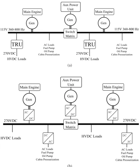
Considering the different load mix, AC (fuel and oil pumps, fans) and DC (actuators, avionics, batteries) co-exist, where generators and an auxiliary power unit (APU) powers the electrical bus. In [4], different architectures for the hybrid EPDS have been analyzed, drawing the conclusion that a full-DC implementation with AC/full-DC rectifiers for the generators without the variable-frequency three-phase distribution is the most efficient in terms of weight. In Fig. 1a, the generators are feeding a three-phase AC bus with variable frequency. The control of the excitation regulates a constant voltage amplitude. TRU are used to provide the HVDC bus at 270V. A switching matrix allows for the connection of the APU to the other bus bars. In the case of a fault in one engine, the bus bars can also be connected to keep the EPDS operational. In Fig. 1b, the generators are directly connected to AC/DC converters that provide the DC bus. AC loads are connected to the DC distribution via a DC/AC inverter.
III. POWERCONVERTER DESCRIPTION
The quadruple active bridge converter has been proposed to be used in aircraft systems in several works [5]–[7]. Its multi-port characteristic made it the suitable candidate to interface different power sources and to guarantee the power exchange among the DC buses.
TRU
115V 360-800 Hz
Main Engine
270VDC HVDC Loads
AC Loads Fuel Pump Oil Pump Cabin Pressurization Gen
115V 360-800 Hz Main Engine
Gen
TRU
270VDC HVDC Loads
AC Loads Fuel Pump Oil Pump Cabin Pressurization Aux Power
Unit
Gen
Switch Matrix
(a)
270VDC
HVDC Loads
AC Loads Fuel Pump Oil Pump Cabin Pressurization
AC Loads Fuel Pump Oil Pump Cabin Pressurization Aux Power
Unit
Gen
Switch Matrix
270VDC
HVDC Loads Main Engine
Gen
Main Engine
Gen
(b)
Fig. 1: Example of an hybrid electrical power distribution systems with AC (a) and DC (b) distribution.
% duty cycle and the phase-shift between the ports regulates the power transfer.
Equation (1) describes the overall power that is processed by a single port, wherenij is the turn ratio between the two ports,Lij is the equivalent inductance from the two ports and
dij is the phase shift angle normalized to 2π.
Pi=X
j6=i
nijViVj
Lijfsw dij(1−2dij) (1)
The Cascaded H-bridge has been extensively adopted for medium-voltage power converters due to its modularity and the possibility to adopt low-voltage devices. Other characteristics, like a reduced output harmonic distortion and ease of control contributed to its success. One of its biggest disadvantages, however, is the necessity to provide isolated DC Links to all the H-bridge cells and the need for the isolating transformer to be designed for the full medium voltage.
If the CHB is adopted for LV applications, this constraint of the transformer isolation is not anymore relevant and the transformer can be optimized for efficiency and power density (i.e., primary and secondary windings can be overlapped to
minimize the stray inductance and the AC losses). Using a multilevel converter for an avionic application with DC Link of 270V would also allow the usage of LV devices with excellent on-state characteristics, still retaining all the advantages of the modular architecture.
This QAB+CHB architecture has already been proposed for solid-state transformer applications [9] and it is shown in Fig. 3. Because only a DC/DC converter with a transformer is present, the system is more compact than a solution where three DC/DC converters are used.
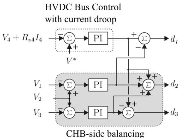
The proposed control of the QAB aims at regulating sym-metrical DC link voltages regardless the power transfer. The schematic of the control is presented in Fig. 4, assuming as a reference the phase-shift of port 4. In this way, the phase-shift
d1−3 are related to the power that is transferred to ports 1-3 to port 4. A PI regulator controls the bus voltage and embeds a droop controller with coefficientRv4. Additional controllers are used to regulate the DC links of the CHB side.
Fig. 2: Quadruple Active Bridge schematic.
Quadruple Active Bridge C
CHB
Fig. 3: A two-port modular smart TRU.
phase-shift PWM allows for a very low Total Harmonic Distortion (THD). Advanced strategies in case of unbalanced power transfer can also be adopted [10]. In the case of a fault in a CHB cell, this can be bypassed and the converter operates normally. In case of a fault of the QAB, the other two phases
CHB-side balancing
HVDC Bus Control
with current droop
1
Fig. 4: Control of the QAB to balance the DC Links.
of the CHB can still transfer power to the DC bus.
The CHB+QAB solution has several degrees of freedom, because the AC side is three-phase and the QAB can be used in 3-1 (three ports AC and one DC) or in 2-2 (two ports for AC and DC) mode. Fig. 5 shows how the CHB+QAB can be used to realize a three port AC/DC+DC converter, with one AC port and two DC ports. The biggest advantage of this kind of approach is the possibility to connect a generator directly to two bus bars, as in Fig. 6. The internal power sharing of the QAB allows for different power to be distributed to the bus bars.
This solution has several degrees of redundancy:
• The three phase AC/DC is composed of six H bridge with
an intrinsic fault tolerant capability.
• Since there are 3 QAB converter, the fault of one QAB
does not interrupt the power flow to the DC buses.
• If a generator ceases to function, the QAB still allows for
the power exchange between the bus bars, allowing for seamless transition to a post-fault condition.
Quadruple Active Bridge C
CHB
Fig. 5: A three-port modular smart TRU.
270VDC
HVDC Loads
AC Loads Fuel Pump Oil Pump Cabin Pressurization
AC Loads Fuel Pump Oil Pump Cabin Pressurization
Aux Power Unit
Gen
270VDC
HVDC Loads Main Engine
Gen
Main Engine
Gen
Fig. 6: Example of an hybrid electrical power distribution systems with smart TRU.
This solution replaces the solid-state switches allowing for the virtual connection of the whole EPDS (with benefits in terms of better utilization of the generators) but still guaran-teeing the galvanic isolation.
IV. EXPERIMENTALRESULTS
cells and a QAB converter, comprising of the high-frequency transformer. Fig. 7 shows the laboratory prototype and Table I lists the parameters.
QAB DC-side cell
CHB cells
QAB AC-side cells
Fig. 7: Picture of the proposed STRU.
TABLE I: Experimental parameters
Vn(V1,V2,V3,V4) 270 V
Pn 3 kW
L1,L2,L3 160 uH
L4 35 uH
Leq 95 uH
C1,C2,C3,C4 0.4 mF
fsw 20 kHz
Fig. 8 shows the schematic of the experimental setup. A Power Supply is connected to the DC port and a Resistive-Inductive (RL) load is connected to the AC port. If a fault occurs, e.g., short-circuit of the switch S3, the H-bridge outputs zero voltage by disabling switches S2 and S3 and switching on S1. During this transition, the QAB port can still be operational, controlling the voltage. After the fault, it can be switched off and the QAB can be reconfigured into a Triple Active Bridge (TAB). A similar procedure can be adopted in the case of an open-circuit fault.
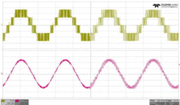
The condition that has to be analyzed is the post-fault operation of the STRU in terms of having unchanged output voltage and DC output voltage. This experiment is shown in the following figures. Fig. 9 shows the AC current and the overall output voltage of the CHB when a fault happens at the time t = 0 s. The remaining CHB cells increase the duty cycles and the current amplitude is unaffected. A higher ripple appears due to the reduction of the effective switching frequency. Fig. 10 shows that at time t = 0 s the lower cell is bypassed. Fig. 11 shows the particular of the DC Link voltages at the moment of the fault. Although the power consumption changes abruptly, the QAB control still regulates the DC voltage.
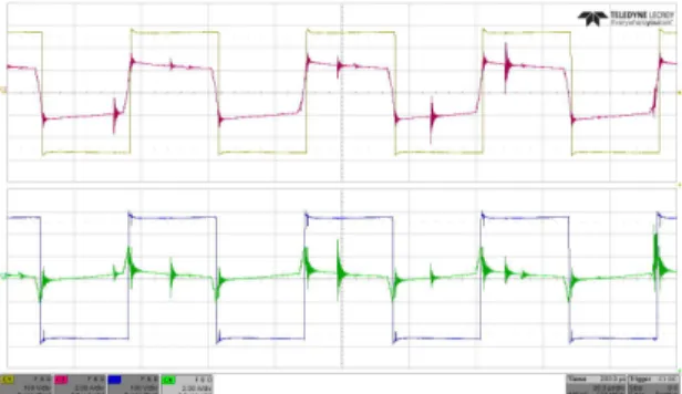
Fig. 12 and Fig. 13 shows the waveforms of the QAB during the transition. The top waveforms refers to the cell that increases its loading while the bottom waveforms refers to the excluded cell. These experiments show how the control of the QAB always regulates the DC voltage regardless the output power.
The efficiency of the QAB was measured with the Yoko-gawa WT1800 with the goal to analyze both the overall
DC Power
Supply RL
Load
Fig. 8: Schematic of the setup for the experiments. The faulty cell is bypassed by forcing an output zero vector.
Fig. 9: Experimental results. AC current and output voltage of the CHB.
efficiency and the efficiency reduction when the QAB is operating in a heavily asymmetrical mode. As it can be seen from Fig. 14, when only one QAB port is providing the full power and the other two ports keep operating, but with no load. Despite the very asymmetrical operating mode, only a small efficiency deterioration of 0.1 % at 2 kW happens.
V. CONCLUSION
Fig. 10: Experimental results. AC voltage and current of the CHB cells when the first module is excluded.
Fig. 11: Experimental results. DC current and AC voltage of the CHB cells when the first module is excluded.
results show how the control of the STRU is resilient to a fault in the AC side.
VI. ACKNOWLEDGEMENT
This work was supported by the Ningbo Science & Technol-ogy Beauro under Grant 2013A31012 and Grant 2014A35007 and the European Research Council (ERC) under the European Unions Seventh Framework Program (FP/2007-2013)/ERC Grant Agreement 616344 HEART.
REFERENCES
[1] M. Sinnet, “787 no-bleed systems: Saving fuel and enhancing opera-tional efficiencies,”Boeing Aero Magazine, vol. 4, 2007.
Fig. 12: Envelope of high frequency waveforms of voltage and current of loaded and unloaded cell during the fault simulation.
Fig. 13: High frequency waveforms of voltage and current of loaded and unloaded cell.
0 500 1000 1500 2000 2500 3000 94
94.5 95 95.5 96 96.5 97
Fig. 14: Efficiency measurement of the QAB converter [6].
[2] P. Wheeler and S. Bozhko, “The more electric aircraft: Technology and challenges.”IEEE Electrification Magazine, vol. 2, no. 4, pp. 6–12, Dec 2014.
[3] T. Yang, S. Bozhko, and G. Asher, “Functional modeling of symmetrical multipulse autotransformer rectifier units for aerospace applications,”
IEEE Transactions on Power Electronics, vol. 30, no. 9, pp. 4704–4713, Sept 2015.
[4] J. Chen, C. Wang, and J. Chen, “Investigation on the selection of electric power system architecture for future more electric aircraft,”
IEEE Transactions on Transportation Electrification, vol. PP, no. 99, pp. 1–1, 2018.
[5] B. Karanayil, M. Ciobotaru, and V. G. Agelidis, “Power flow manage-ment of isolated multiport converter for more electric aircraft,” IEEE Transactions on Power Electronics, vol. 32, no. 7, pp. 5850–5861, July 2017.
[6] G. Buticchi, L. F. Costa, D. Barater, M. Liserre, and E. Dominguez, “A quadruple active bridge converter for the storage integration on the more electric aircraft,”IEEE Transactions on Power Electronics, 2018,in press.
[7] G. Buticchi, L. Costa, and M. Liserre, “Improving system efficiency for the more electric aircraft: A look at dcdc converters for the avionic onboard dc microgrid,”IEEE Industrial Electronics Magazine, vol. 11, no. 3, pp. 26–36, Sept 2017.
[8] L. F. Costa, G. Buticchi, and M. Liserre, “Quad-active-bridge dc-dc converter as cross-link for medium-voltage modular inverters,” IEEE Transactions on Industry Applications, vol. 53, no. 2, pp. 1243–1253, March 2017.
[9] M. Liserre, M. Andresen, L. Costa, and G. Buticchi, “Power routing in modular smart transformers: Active thermal control through uneven loading of cells,”IEEE Industrial Electronics Magazine, vol. 10, no. 3, pp. 43–53, Sept 2016.