This is a repository copy of Dynamic snap-through for morphing of bi-stable composite plates.
White Rose Research Online URL for this paper: http://eprints.whiterose.ac.uk/81014/
Version: Submitted Version
Article:
Arrieta, A.F., Wagg, D.J. and Neild, S.A. (Submitted: 2011) Dynamic snap-through for morphing of bi-stable composite plates. Journal of Intelligent Material Systems & Structures, 22 (2). 103 - 112. ISSN 1045-389X
https://doi.org/10.1177/1045389X10390248
Reuse
Unless indicated otherwise, fulltext items are protected by copyright with all rights reserved. The copyright exception in section 29 of the Copyright, Designs and Patents Act 1988 allows the making of a single copy solely for the purpose of non-commercial research or private study within the limits of fair dealing. The publisher or other rights-holder may allow further reproduction and re-use of this version - refer to the White Rose Research Online record for this item. Where records identify the publisher as the copyright holder, users can verify any specific terms of use on the publisher’s website.
Takedown
If you consider content in White Rose Research Online to be in breach of UK law, please notify us by
Dynamic snap-through for morphing of bi-stable composite
plates
A. F. Arrieta, D.J. Wagg and S.A. Neild
Department of Mechanical Engineering,University of Bristol,
University Walk, Bristol, U.K BS8 1TR
Abstract
Composite laminate plates designed to have two statically stable configura-tions have been the focus of recent research, with a particular emphasis on morphing applications. In this paper we consider how external vibration en-ergy can be used to assist with the actuation between stable states. This is of interest in the case when surface mounted macro-fibre composites (MFC) actuators are employed as the actuation system. Typically, these type of actuators have been found to require very high voltage inputs to achieve significant levels of actuation authority. Therefore, assisting the actuation process will allow lower voltages and/or stiffer plates to be actuated. Two bi-stable plates with different thickness, [04 −904]T and [02 −902]T, were
tested. The results show a significant reduction in the force required to change state for the case where dynamic excitation provided by an MFC ac-tuator is used to assist the process. This strategy demonstrates the potential of dynamically assisting actuation as a mechanism for morphing of bi-stable composites.
Keywords: Bi-stable composites, morphing structures, dynamic snap-through,
macro-fibre composites.
1
INTRODUCTIONBy coupling bi-stable composite specimens with actuators to induce changes of shape (snap-through), morphing structural elements are created which have the potential to be incorporated into more complex structures.
In the past, different types of actuators have been employed to achieve this goal. The concept of using shape memory alloy (SMA) wires to induce snap-through has been in-vestigated, however its integration proved difficult and the implementation with bi-stable composites remains challenging (Dano and Hyer, 2003). More suitable for integration with bi-stable composites are flexible piezo-electric actuators such as macro-fibre com-posite (MFC) actuators (Wilkie et al., 2000). In previous studies MFC actuators driven by a quasi-static voltage have been used to induce snap-through by statically loading bi-stable composites (Bowen et al., 2007; Portela et al., 2008; Schultz et al., 2006). A key limitation of the applicability of this concept is the low actuation authority achieved with static actuation from MFC actuators.
To address this problem, the idea of dynamically inducing snap-through in multi-stable composite plate is investigated in this paper. This actuation strategy exploits the dynamics of the bi-stable structure in order to achieve the change between stable shapes more efficiently — effectively increasing the actuator’s authority to induce snap-through. The justification for aerospace applications is that all these structures will operate in a dynamic environment, and so exploiting the dynamic excitation can be thought of as a form of energy harvesting.
In this paper, two bi-stable plate specimens, [04−904]T and [02−902]T, with surface
mounted MFCs as actuators, are employed to experimentally demonstrate the morphing concept of dynamically induced snap-through. The main characteristics of the dynamic response of the plates are presented, based on previous works by the authors for similar bi-stable composites (Arrieta et al., 2007, 2009a). Taking advantage of key features of the response, particular excitation frequencies are selected such that large ampli-tude oscillations of the plate can be induced. This mechanism generates a mechanical advantage increasing the authority of the actuator to trigger snap-through.
Two types of tests are conducted. First, passive testing in which dynamically in-duced snap-through is triggered using a shaker as external source of excitation is carried out. The snap-through force is measured as a function of the forcing frequency for the experimental specimen. Second, active tests are conducted in which the force required to dynamically trigger snap-through under the combined action of the MFC actuator and the external shaker is measured. The resulting actuation strategy is shown to offer po-tential as a configuration control strategy for morphing applications involving bi-stable composites elements.
2
DYNAMIC RESPONSEThe concept of dynamically inducing snap-through as a morphing strategy is demon-strated by testing two [04−904]T 300x300mm and [02−902]T 200x200mm bi-stable plates
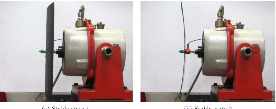
with an MFC 8557-S1 bonded to the surface. The two stable configurations of the 8-ply [04 −904]T bi-stable specimen are shown in Figure 1. The material properties of the
(a) Stable state 1 (b) Stable state 2
Figure 1: Stable states of a bi-stable plate.
P roperty F ibrevol. P ly thickness Density ρ Exx Eyy Ga
xy νxya =νyxa
[%] [mm] [kg/m3] [GP a] [GP a] [GP a]
[image:4.595.95.538.70.246.2]V alue 57.7 0.131 0.128 164 12 4.6 0.3
Table 1: Material properties for a ply of HexPly 8557 IM7 used to manufacture the bi-stable experi-mental specimens.
sured signals are pass through a Kistler signal conditioner. The experimental assembly is shown schematically in Figure 3.
The dynamic behaviour of similar bi-stable plates without a surface mounted MFC actuator were studied in previous papers by the authors (Arrieta et al., 2009a,b). In this paper, the same testing procedure is used to study the dynamics of the bi-stable plate specimens with MFC actuator attached to their surface. For further details of the dynamic testing methodology can be found in (Arrieta et al., 2009a,b).
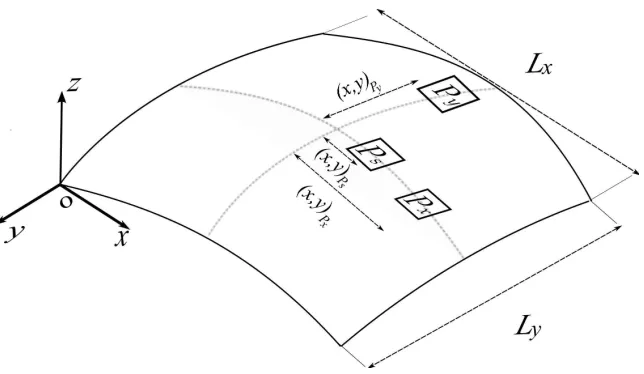
The dynamic response of a grid of points on the bi-stable specimens is measured with a laser vibrometer to obtain a series of frequency response diagrams. The results allowed both the linear and nonlinear dynamic response of the bi-stable plate specimens to be investigated. The measured pointsPx,Py, andPs for both bi-stable plate specimens are schematically shown in Figure 4. The position of the measured points are (225,150)Px,
(150,225)Py, and (180,150)Ps, for the 8-ply plate, and (150,100)Px, (100,150)Py, and
(130,100)Ps, for the 4-ply plate with respect to the frame of reference shown in Figure 4.
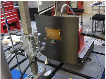
Figure 2: Bi-stable plate [04−904]T 300x300 [mm] made of carbon fibre epoxy HexPly 8557 IM7 with an MFC 8557-S1 surface mounted directly above the central attachment point used to connect the plate to the shaker.
[image:5.595.149.479.454.711.2]Figure 4: Grid of points measured on the tested specimens. Point Px describes the out-of-plane deflection in low curvature-direction, coinciding with the x-coordinate, and point Py describes the out-of-plane deflection in the high curvature-direction for state 2. Point Ps is used to measure large amplitude oscillations for the plate. This is because for some parameter values, pointsPx andPy can go beyond the range of the laser vibrometer.
the presence of nonlinear behaviour, as seen in Figure 6 for regions around twice the frequency of modes w1(8p) and w2(8p). The nature of the nonlinear oscillations indicate the characteristics of 1/2 subharmonic resonances of modesw(81p) andw(82 p), as expected from well known literature results (Emam and Nayfeh, 2004; Nayfeh and Mook, 1979).
To test the actuation authority of the MFC actuator for the 8-ply plate, frequency response diagrams for both stable states of the specimen are acquired. These diagrams were obtained while exciting the 8-ply specimen with the MFC actuator driven with a constant 500 V voltage signal. The frequency response diagram for pointPx in state 1 and point Py in stable state 2, are shown in Figures 7(a) and 7(b). These figures give an indication of the MFC actuator’s authority showing the achievable displacements obtained for the 8-ply specimen. The observed dominant modes coincide with those shown in the frequency response functions obtained with the external shaker as an excitation source. The large modal responses for modes w18p and w28p are, in part, a result of the chosen position of the MFC actuator. In this case, modew38p is not excited as the location of the moments applied by the MFC lie over nodal lines of the associated mode shape. The positioning of the actuator was chosen so that its edges perpendicular to the fibre direction did not coincide with the nodal lines of the deflection shapes for state 2. This is done as it was found that the state 2 was the more compliant configuration of the tested bi-stable plates. Due to the bi-stability and the orthogonal symmetry of the curvatures (Arrieta et al., 2009b) of bi-stable plates this optimized positioning could only be achieved for one stable configuration. As a result we focused first on achieving snap-through from state 2 to state 1.
15 25 35 45 0 0.5 1 1.5 2 2.5 3 3.5 Frequency [Hz] D is p la ce m en t [m m
] w1 w3
(a)
15 25 35 45
0 0.05 0.1 0.15 0.2 0.25 0.3 0.35 0.4 Frequency [Hz] D is p la ce m en t [m m ] w
1 w2
[image:7.595.99.521.132.308.2](b)
Figure 5: Experimental frequency response diagrams of [04−904/M F C]T 8-ply plate with surface mounted MFC for state 2, forcing amplitudeFo= 1N. (a) PointPy. (b) PointPx. Vertical lines show linear natural frequencies.
32 34 36 38 40
1 1.5 2 2.5 3 3.5 4 Frequency [Hz] D is p la ce m en t [m m ] (a)
32 34 36 38
1.5 2 2.5 3 3.5 4 4.5 5 5.5 Frequency [Hz] D is p la ce m en t [m m ] (b)
[image:7.595.93.519.464.657.2]15 25 35 45 0 0.1 0.2 0.3 0.4 0.5 0.6 0.7 0.8 Frequency [Hz] D is p la ce m en t [m m ] (a)
15 25 35 45
[image:8.595.98.518.77.256.2]0 0.1 0.2 0.3 0.4 0.5 0.6 0.7 Frequency [Hz] D is p la ce m en t [m m ] (b)
Figure 7: Experimental frequency response of 8-ply plate with MFC as actuator for a peak to peak voltage of 500V. (a) Response for pointPx of state 1. (b) Response for pointPy of state 2.
3
DYNAMICALLY INDUCED SNAP-THROUGH AS A MORPHINGSTRATEGY
The idea of dynamically inducing snap-through is achieved by exploiting the dynamics of the snap-through mechanism. In terms of a potential energy function, the two stati-cally stable configurations of a bi-stable composite plate correspond to stable equilibria points separated by a unstable equilibrium. The potential energy function is shown schematically by the bold line in Figure 8. To trigger snap-through from one stable state to the other, energy needs to be put into the system such that it is pushed up and over the energy hilltop separating the two potential wells. This is shown schematically as the ball representing system’s state, as shown in Figure 8. In other words, the dy-namic response of the bi-stable plates is restricted to oscillations confined to a stable state unless enough energy is put into the system to deflect it beyond the hilltop. In physical terms this hilltop is defined as a deflection threshold or critical displacement. The critical displacement for an arbitrary point of a bi-stable plate is related to the static deflection required to change from one stable state to the other as seen in Figure 9. The asymmetry in the potential energy function is explained below.
We assume that the deflection shape of the bi-stable plate may be modelled with linear mode shapes, such that the relative deflection at any instant of the forcing period between points remains linearly proportional. Under this assumption, once a point is deflected past its critical displacement a snap-through is triggered as all the points in the plate must have also reached their particular threshold due to the proportionality relation of the mode shapes. For the 8-ply specimen the critical displacement for point
Figure 8: Potential well schematic diagram for a bi-stable plate under the action of an MFC actuator.
[image:9.595.149.474.396.725.2]0 2 4 6 8 10 12 −3
−2 −1 0 1 2
Time [s]
D
is
p
la
ce
m
en
t
[m
m
]
(a)
0 2 4 6 8 10 12
−40 −30 −20 −10 0 10 20
Time [s]
F
o
rc
e
[N]
[image:10.595.101.521.75.253.2](b)
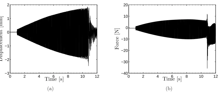
Figure 10: Experimental response showing a dynamically induced snap-through from state 2 to state 1 for a 8-Ply plate with MFC. Shaker forcing frequency Ω=35.5 Hz. (a) Displacement time series. (b) Force time series.
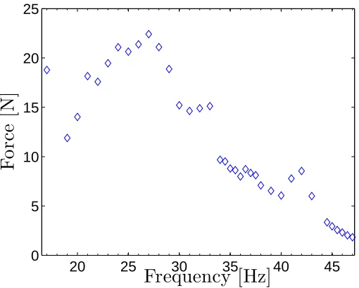
The concept of dynamically inducing snap-through was studied employing a shaker to excite the 8-ply bi-stable specimen past its critical displacement for a range of forcing frequencies. Sinusoidal forcing inputs with linearly increasing amplitudes were employed to drive the specimen until snap-through was triggered. The signals used to excite the plate were fine tuned such that the snap-through for each frequency was triggered approximately 10 s after the start of the linearly growing amplitude input. A time series for the displacement of point Ps on the plate and the measured force amplitude for a dynamically induced snap-through with the shaker as actuator are presented in Figure 10. The measured snap-through force from stable state 2 to stable state 1 for the bi-stable plate-MFC actuator under the sole action of the shaker is shown in Figure 11. The regions of lower snap-through force coincide with the linear (primary) and subharmonic (secondary) resonances of the bi-stable plate. This can be deduced by comparing the frequency response diagram in Figures 5 and 6 with the snap-through force frequency relation given in Figure 11. The snap-through force relationship enables us to find the frequency ranges requiring less actuation to induce snap-through, providing the target actuation frequencies most favourable for achieving morphing of the bi-stable plate-MFC actuator structures.
20 25 30 35 40 45 0
5 10 15 20 25
Frequency [Hz]
F
o
rc
e
[image:11.595.179.434.82.287.2][N]
Figure 11: Experimental forcing amplitude required to dynamically induce snap-through from state 2 to state 1 for a 8-Ply plate with MFC actuator attached, but not active during the tests.
can be exploited by coupling the action of the MFC actuator to it and exploiting the dynamic characteristics of the structure, such as the resonant frequencies. Furthermore, the morphing structure can be devised in order to maximize this effect by designing the resonances, or adapting them by active means, to be close to the excitation frequencies. This form of energy harvesting is employed as an actuation strategy for morphing of the bi-stable plate-MFC structure.
Experiments using an external shaker are carried out to simulate the external energy provided by perturbations loading the structure. The actuation strategy consisted of combining the actuation of the MFC with excitation from the external shaker, targeting the frequencies identified to require minimum force to trigger snap-through, shown in Figure 11. As seen in Figure 11 the frequency ranges where minimum force is required to trigger a snap-through are around modew3and the subharmonic oscillations. In order to
excite modew8P
3 an MFC large enough such that its edges lie close to those of the plate
is required, however these type of large actuators are impractical. Therefore, for the current configuration the most efficient strategy is to exploit the dynamic characteristics of the subharmonic resonances. A subharmonic resonance is induced with the external shaker and the MFC targeted the subharmonic frequency of the plate response (at half the forcing frequency of the shaker). As a result, the energy of the MFC is directly exciting the frequency causing large amplitude response in the subharmonic resonance mechanism, effectively achieving a mechanical advantage (Arrieta et al., 2009a; Nayfeh, 2000).
15 20 25 30 35 40 45 0
0.5 1 1.5 2
Frequency [Hz]
D
is
p
la
ce
m
en
t
[m
m
]
[image:12.595.175.434.80.286.2]Static critical displacement
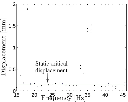
Figure 12: Experimental displacement of the pointPsjust before the triggering of a dynamically induce snap-through from state 2 to state 1 for a 8-Ply plate with MFC actuator attached (not active during the tests). Away from linear and nonlinear resonance thedynamic critical displacement is very close to 0.2 mm which corresponds to the measuredstatic critical displacement.
As the subharmonic oscillation consists of two frequency components it is difficult to measure the relative phase of the response, in a linear sense. The experiments show that the action of the MFC produces a complex interaction with the dynamic response of the plate which after a brief transient period becomes phase locked, causing a significant increase in amplitude. At this point the dynamic critical displacement threshold is surpassed and snap-through is triggered as seen in Figure 13(a).
The maximum force exerted by the shaker before the initiation of the snap-through process is chosen as the comparison measure for the results shown in Figure 14. The maximum mechanical advantage is observed at around twice the natural frequency of mode w28p for stable state 2, this is at 36.2 Hz, of the test specimen. As the forcing frequency moves away from this range the actuation capability of the MFC actuator diminishes considerably as the subharmonic mechanism loses its effectiveness. Moreover, due the difference in the deflection shape as the forcing frequency diverts from the subharmonic of mode w28p, the effect of the MFC action actually increases the snap-through force. This mechanism could be employed to enhance the stability of a desired configuration avoiding undesired snap-through, however this is beyond the scope of this paper.
For the 8-ply-MFC plate a maximum reduction of 1.46 N or 15.8 % of the shaker force to induce snap-through is achieved compared to the measured force under the lone action of shaker at a forcing frequency of 36.2 Hz. In principle if a powerful enough MFC or an arrangement of several MFC were available, a dynamically triggered snap-through could be induced, achieving a self morphing structure.
0 5 10 15 −3 −2 −1 0 1 2 3 Time [s] D is p la ce m en t [m m ] (a)
0 5 10 15
−40 −30 −20 −10 0 10 20 Time [s] F o rc e [N] (b)
0 5 10 15
[image:13.595.97.521.67.412.2]−500 0 500 Time [s] V o lt a g e [V] (c)
Figure 13: Experimental response showing a dynamically induced snap-through from state 2 to state 1 at 15 s. Forcing frequency Ω=36.4 Hz. (a) Displacement time series. (b) Force time series. (c) MFC signal targeting modew2causing the subharmonic. Forcing frequency Ω=18.1 Hz. Voltage amplitude
500 V.
34 35 36 37 38
7 7.5 8 8.5 9 9.5 10
Frequency [Hz]
F
o
rc
e
[N]
Ling
Ling+MFC
Maximum
reduction 15.8 %
[image:13.595.165.444.488.693.2]15 20 25 30 35 40 45 0 0.5 1 1.5 Frequency [Hz] D is p la ce m en t [m m ] (a)
[image:14.595.101.519.77.256.2]15 20 25 30 35 40 45 0 0.2 0.4 0.6 0.8 1 Frequency [Hz] D is p la ce m en t [m m ] (b)
Figure 15: Experimental frequency response [02−902/M F C]T 4-ply plate for state 2. (a) For point
Px, forcing amplitudeFo= 1.5N. (b) For pointPy, forcing amplitudeFo = 0.5N.
25 Hz andw(43 p) at 50 Hz, as seen in the frequency response diagrams given in Figure 15. The superscript (4p) is used in the notation to differentiate the modes of the 4-ply
plate from those of the 8-ply plates. The observed quantitative difference in the modal frequencies between the 4-ply and 8-ply plates, does not affect the mechanisms causing the observed nonlinear dynamic behaviour. A frequency response diagram obtained using the MFC as the only external actuator, shown in Figure 16, indicates that with the current arrangement the highest actuation authority is obtained around the mode at 22.8 Hz.
15 20 25 30 35 40 45
0 0.1 0.2 0.3 0.4 0.5 0.6 0.7
Frequency [Hz]
D
is
p
la
ce
m
en
t
[m
m
]
Figure 16: Experimental frequency response [02−902/M F C]T 4-ply plate for state 2, pointPy. Forcing amplitudeFo= 1.0N, frequency range Ω=[16,50].
[image:14.595.175.439.446.651.2]to induce snap-through as for the 8-ply plates is implemented for the new 4-ply plate specimen. The results for the required force to induce snap-through with the shaker compared to those of the combined action of the MFC actuator and the shaker are shown in Figure 17. It can be seen that for the values closer to twice the natural
fre-44 45 46
0 1 2 3 4 5
Frequency [Hz]
F
o
rc
e
[N]
Ling
Ling + MFC
[image:15.595.183.433.155.357.2]Maximum reduction 50 %
Figure 17: Dynamic snap-through force comparison for a 4-Ply Plate. ♦shaker induced. + shaker plus MFC induced. MFC signal amplitude 500 V.
quency of modew(41 p) the effect of the MFC is maximised. The maximum reduction of 2 N or 47.6 % of the original force required to trigger snap-through under the sole action of the shakeris is obtained for a forcing frequency of 45 Hz.
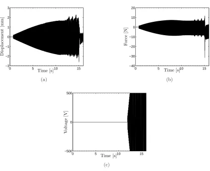
Figures 18(a),18(b), and 18(c) show the displacement, force and MFC actuation signal time series respectively. It can be seen that the snap-through is triggered 0.1 after the maximum amplitude of the MFC signal is reached. Therefore, the dynamic actuation strategy may be seen as a pulse signal acting only over reduced time intervals on the morphing component minimising interaction with the rest of the structure
0 5 10 15 −4 −2 0 2 4 6 8 Time [s] D is p la ce m en t [m m ] (a)
0 5 10 15
−8 −6 −4 −2 0 2 4 6 Time [s] F o rc e [N] (b)
0 5 10 15
[image:16.595.95.521.68.411.2]−500 0 500 Time [s] V o lt a g e [V] (c)
Figure 18: Experimental response showing a dynamically induced snap-through from state 2 to state 1 at 12 s. Forcing frequency Ω=44.8 Hz. (a) Displacement time series. (b) Force time series. (c) MFC signal amplitude 500 V.
4
CONCLUSIONS
The concept of dynamically inducing snap-through on bi-stable composites as a morph-ing strategy has been investigated. Bi-stable plate-MFC actuator morphmorph-ing specimens were constructed to carry out this work. An actuation strategy based on dynami-cally inducing snap-through exploiting the linear and nonlinear dynamics of a bi-stable plate-MFC actuator structure is developed. The dynamic response of the specimens is exploited in order to choose the most efficient morphing strategy, taking into account the response of the structure and the MFC actuators capabilities.
to investigate new possible mechanisms for self-morphing structures.
ACKNOWLEDGEMENTS
The authors would like to acknowledge the support of the ORS scheme; Andres F. Arrieta is funded through an ORS scholarship.
References
Arrieta, A.F., Mattioni, F., Neild, S.A., Weaver, P.M., Wagg, D.J., and Potter, K. 2007. “Nonlinear dynamics of a bi-stable composite laminate plate with applications to adaptive structures”. In 2nd European Conference for Aero-Space Sciences, Brussels,
2007.
Arrieta, A.F., Neild, S.A., and Wagg, D.J. 2009a “Nonlinear dynamic response and modelling of a bi-stable composite plate for applications to adaptive structures”.
Non-linear Dynamics, 58:259–272.
Arrieta, A.F., Wagg, D.J. and Neild, S.A. 2009b. “Modelling of a bi-stable composite plate for adaptive structures”. In 50th AIAA/ASME/ASCE/AHS/ASC Structures, Structural Dynamics, and Materials Conference 17th 4 - 7 May 2009, Palm Springs,
California.
Bowen,C R. , Butler, R.,Jervis, R. , Kim, H.A., and Salo, A.I.T. 2007. “Morphing and shape control using unsymmetrical composites”. Journal of Intelligent Material
Systems and Structures, Vol. 18:89–98,
Carrella, A., Mattioni, F., A. Diaz, A.F, Friswell, M., Wagg, D.J., and Weaver, P.M. 2008. “Static And Dynamic Analysis Of A Bistable Plate For Application In Morphing Structures”. In 7th European conference on structural dynamics, july 7-9,
Southamp-ton, UK..
Dano, M.-L., and Hyer, M.W. 1998. “Thermally-induced deformation behavior of unsymmetric laminates”. International Journal of Solids and Structures, 35:2101– 2120.
Dano, M.-L., and Hyer, M.W. 2002. “Snap-through of unsymmetric fiber-reinforced composite laminates”. International Journal of Solids and Structures, 39:175–198.
Dano, M.-L., and Hyer, M.W. 2003. “Sma-induced snap-through of unsymmetric fiber-reinforced composite laminates”. International Journal of Solids and Structures, 40: 5949–5972.
Diaconu, C. G., Weaver, P. M., and F. Mattioni, F. 2008. “Concepts for morphing airfoil sections using bi-stable laminated composite structures”. Thin-Walled Structures, 46: 689–701.
Hyer, M.W. 1981. “Some observations on the cured shapes of thin unsymmetric lami-nates”. Journal of Composite Materials, 15:175-194.
Mattioni, F., Weaver, P.M., Potter, K., and Friswell, M.I. 2005. “Multi-stable compos-ites application concept for morphing aircraft”. InSixteenth International Conference
on Adaptive Structures and Technologies.
Nayfeh, A.H. and Mook, D.T. 1979. “Nonlinear Oscillations”. John Wiley & Sons.
Nayfeh, A.H. 2000. “Nonlinear Interactions, Analytical, Computational, and
Experi-mental Methods”. John Wiley & Sons.
Portela, P.,Camanho, P., Weaver, P.M., and Bond, I. 2008. “Analysis of morphing, multi stable structures actuated by piezoelectric patches”. Computers and Structures, 86: 347-356.
Potter, K D and Weaver, P.M. 2004. “A concept for the generation of out-of-plane distortion from tailored frp laminates”. Composites, Part A., 35:1353–1361.
Schultz, M.R. and Hyer, M.W. 2003. “Snap-through of unsymmetric cross-ply laminates using piezoceramic actuators”. Journal of intelligent material systems and structures, 14:795–814.
Schultz, M.R., Hyer, M.W., Williams, R.B., Wilkie, W.K., and Inman, D.J. 2006. “Snap-through of unsymmetric laminates using piezocomposite actuators”.Composite
Science and Technology, 66:2442–2448.
Sokorin, S.V. and Terentiev, A.V. 1998. “On modal interaction, stability and nonlinear dynamics of a model two d.o.f. mechanical system performing snap-through motion”.
Nonlinear Dynamics, 16:239–257.
Tsai, S. W. and Hahn, H. T 1980. “Introduction to Composite Materials”. Technomic Publishing Company, Inc..
Wilkie, W. K., Bryant, R. G.,High, J. W. , Fox, R. L., Hellbaum, R. F., Jalink Jr., A., Little, B.D. and Mirick, P.H. 2000. “Low-cost piezocomposite actuator for structural control applications”. In 7th Annual International Symposium on Smart Structures
![Figure 5: Experimental frequency response diagrams of [04mounted MFC for state 2, forcing amplitude − 904/MFC]T 8-ply plate with surface Fo = 1 N](https://thumb-us.123doks.com/thumbv2/123dok_us/7994298.206602/7.595.93.519.464.657/figure-experimental-frequency-response-diagrams-forcing-amplitude-surface.webp)